
Super-Silent Fans Installation Instructions for the Epilog Mini and Helix
How do I install the Super-Silent Fans in my Mini or Helix?
Machine Types: Epilog Mini 18/24 and Helix
Tools Needed:
#1 Phillips Head Screwdriver
5/16 nut driver
Turn off and unplug the engraver from the power source.
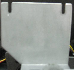
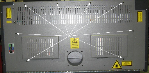
Facing the rear of the machine, remove the eight Phillips screws which secure the rear panel to the machine.
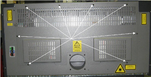
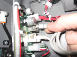
Picture 1
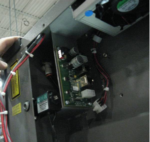
The laser tube is silver in color and sits directly above the exhaust outlet. Disconnect the gray communication cable from the left side of the laser tube by pressing its plastic tab and pulling it free from the laser tube.
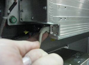
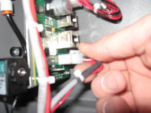
Picture 2
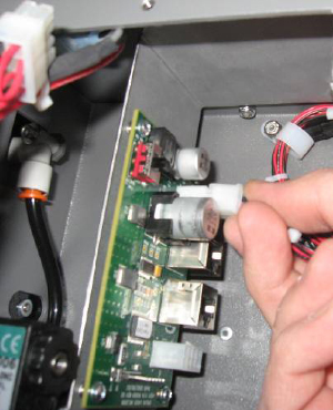
Locate the red and black electrical wires that lead from the laser. follow the wires to the white connector and disconnect the electrical connection to the laser. To unlock the connector, press down on the plastic tab of the connector and pull free from the plug of the wiring harness.
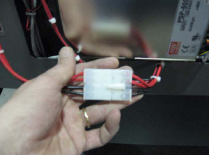
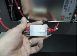
Picture 3
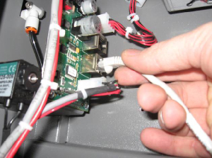
Unplug the Red Dot Pointer, located on the right side of the laser tube. There is a small red and black wire that comes from the diode and connects to a black connector. Disconnect this connector by pressing on the plastic tab and pulling the connector free.
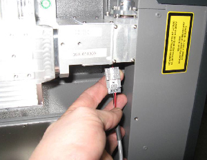
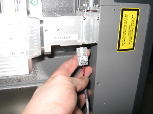
Picture 4
The laser is mounted via three captive screws, two on the right hand side and one on on the left side of the laser tube and two mounting pins. The pins retain the laser in the machine when the captive mounting screws are loosened. The captive mounting screws are identified by the green ring surrounding the Phillips screws. Loosen the Phillips screws all the way. The laser will loosen slightly, but the mounting pins will keep it in the machine. See pictures 5 and 6 below for location of the captive screws and one of the mounting pins. The mounting/guide pin on the right side of the machine is hidden behind the laser's heat sinks (fins).
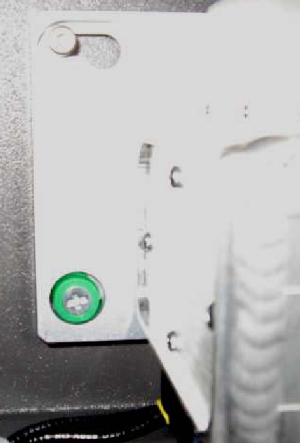
Picture 5 - Captive screw and mounting pin
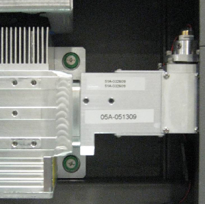
Picture 6 - Right side of the laser assembly
To remove the laser, gently slide the laser to the left and life the laser off of the mounting/guide pins. The laser can now be removed from the machine. Set the laser to one side.
Using the 5/16 nut driver, remove the four 5/16 nuts which secure the fan panel to the machine and remove the fan panel.
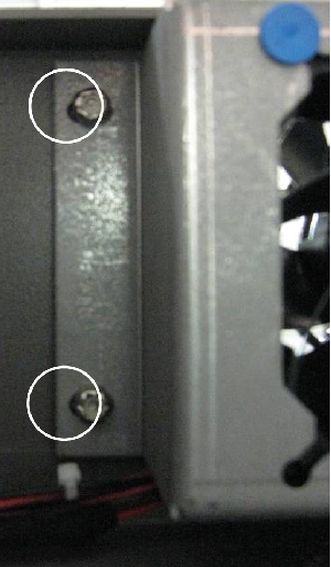
Picture 7 - Left side of the fan panel
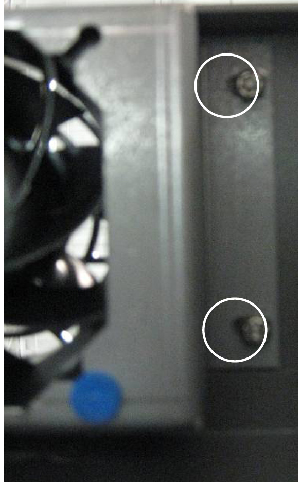
Picture 8 - Right side of the fan panel
Install the new fan panel on the mounting studs. Do not tighten the nuts at this time, only start the nuts with 2-3 turns.
Install the fan control PCB mount. The mount fits on the right side of the machine between the fan panel mount and the mounting screws. The fan control PCB mount has two cutouts, as shown in Picture 9.
Picture 9 - Mounting slots fan control PCB
These cutouts fit over the fan panel mounting studs. To install the fan control PCB mount, push the fan panel up and slip the mounting into place.
Picture 10
Gently tighten the fan's 5/16 nuts, which secure the fan panel to the chassis. Note: The fan panel mounting studs are aluminum - do not over tighten them or they may break!
Plug the fan panel into the upper white connector on the fan panel.
Picture 11
Connect the main harness data cable to the lower data port on the fan control PCB.
Picture 12
Connect one end of the new data cable to the upper data port on the fan control PCB (Picture 12) and connect the other end to the data port on the laser.
Picture 13
Plug in the main fan harness into the lower white connector on the fan panel PCB.
Picture 14
Reinstall the laser tube into the machine. Hang the laser on the mounting guide pins. Gently slide the laser to the right until it stops. Tighten the green captive screws.
Connect the laser power.
Picture 15
Connect the Red Dot Pointer.
Picture 16
Install the rear panel of the laser engraver.
Picture 17
Alignment of the machine should not be necessary.
Attachments
No attachments.
Related Articles
No related articles.