
X-Axis Rail Assembly Replacement on the Epilog Mini
How do I replace the x-axis rail on my Epilog Mini?
Machine Type: Epilog Mini 18/24
Tools Needed:
Large Philips head screw driver
Small Philips head screw driver
Flat head screw driver
3/32 Allen wrench
Torx Screw Driver with 3/32 hex bit
Intro:
This procedure details steps to replacing the X-Axis rail on the Legend Mini. The X-Axis rail guides the laser head from left to right. Before starting on this procedure, clean a section of a desk or table to work on because this procedure requires the X-Axis Assembly to be completely taken apart.
Procedure:
Unplug the power cord from the machine and the wall.
Remove both side panels.
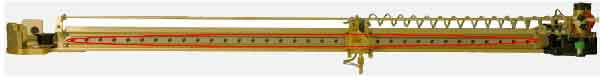
Remove the X-Axis Assembly
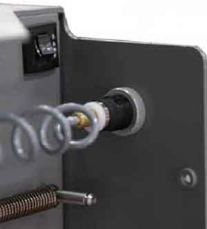
a. Disconnect air intake. Push in the white ring and then pull the air hose out.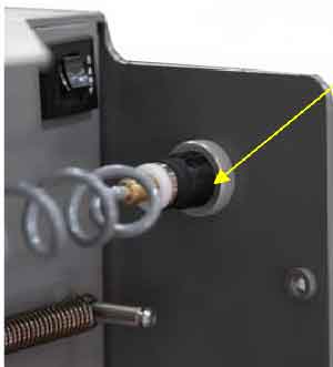
b. Clip the white electrical tie around the white ribbon cable.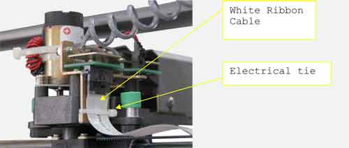
c. Disconnect white ribbon cable.
d. Unscrew the green captured screw on the left side of the X-beam.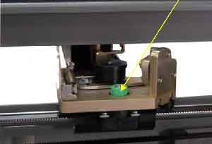
e. Unscrew the two green captured screws on the right side of the X-beam.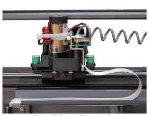
f. Lift the I-beam carefully. Use caution when lifting the right side of the X-beam. Bring the right side forward a little to ensure the motor clears the frame rail.Place the X-Axis Assembly on a clean table top. Make sure the Laser head does not rest on the table.
Relax the belt.
a. On the left side of X-beam there is a pulley system. Unscrew both of the screws.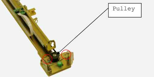
b. Push in the pulley and simultaneously tighten the left screw.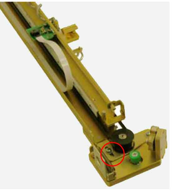
Remove the belt by the unscrewing the four screws on the two belt clamps.
Unscrew the air intake from the laser head.
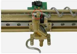
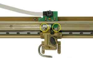
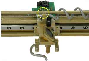
Unscrew the small control board from the laser head
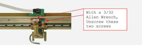
Unscrew the 34 3/32 hexagonal screws on the rail.
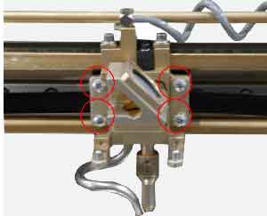
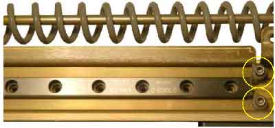
Unscrew the four hexagonal screws with the white stops. There are two of these screws on each side of the X-Axis rail.
Slip the Laser head off the rail
Replace the rail:
a. Slide the laser head onto the rail.
b. On the right side of the rail there are engravings by the manufacturer. Locate the arrows in these engravings. To position the rail point, put the engravings on the right side of the X-beam and point the arrows down.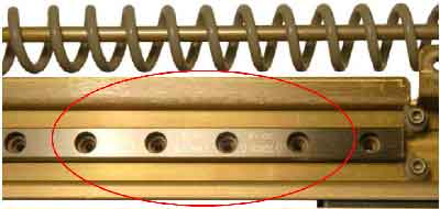
c. While screwing in the 34 3/32 hex screws for the rail, press down firmly on the top of the rail. This will ensure straightness to the rail.
d. Screw in the four hexagonal screws with white stoppers.
e. Torque the 34 hex screws.Screw in the small control panel to the laser head.
Screw in the air intake.
Slide the laser head back and forth along the rail to ensure smooth movement.
Replace the belt.
a. Remove the X-motor.
i.Unscrew the three captive screws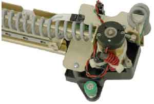
ii.Lift the motor out of the bracket.
b. Put the left side of the belt into the right side of the laser head, screw in the plate.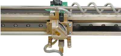
c. Loop the belt through the bracket and around the black pulley. Pull the belt to the left side of the I-beam.
d. With the index finger loop the belt around the silver spindle of the X-motor.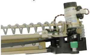
e. Put the X-motor back on the bracket and screw in the three captive screws.
f. Loop the right end of the belt around the left side of X-beam.
g. Screw in the right end of the belt into the left side of the laser head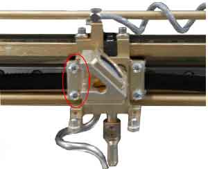
h. Tighten the belt with the pulley system on the left side of the X-beam.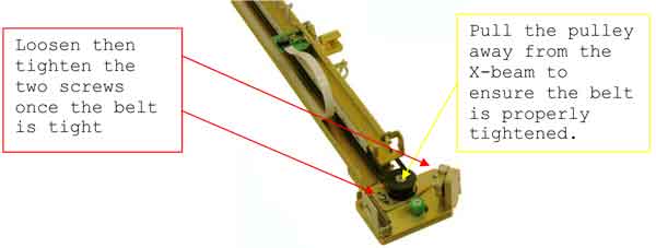
Replace the X-beam cover
Put the X-Axis Assembly back in the machine. Make sure not too hit the frame rails.
Screw in the green captured screws on each side of X-beam.
Reconnect air intake.
Replace the side panels
Attachments
No attachments.