安全第一:内部の電子機器に触れたり、接続を解除したりする前に、レーザーシステムの電源が完全に切れていること、および主電源コードが壁のコンセントから抜かれていることを確認してください。露出している電源装置の部品には絶対に触れないでください。
重要:制御基板、バックプレーン、およびその他の電子部品は、静電気放電(ESD)の影響を受けやすくなっています。これらの部品を取り扱う際は、損傷を防ぐため、必ず機械の金属製シャーシに接地された静電気防止リストストラップを装着してください。
第1部:制御基板の取り外し
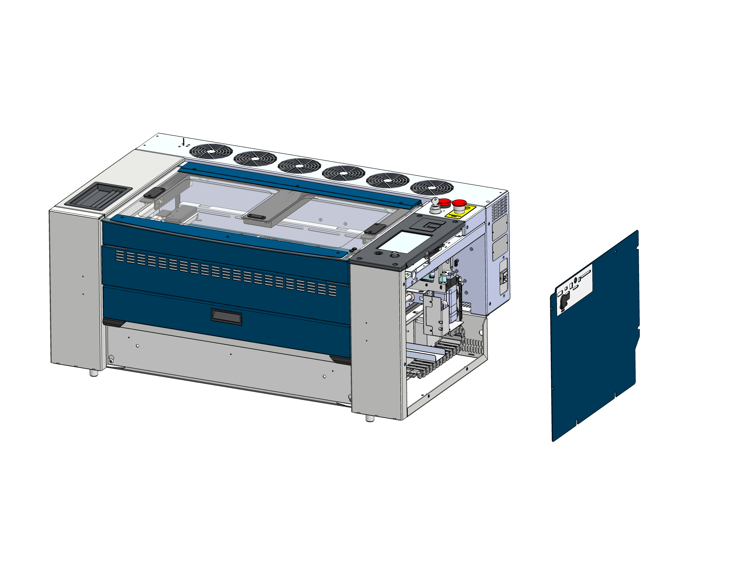
サイドパネルを取り外す
レーザー筐体の右側パネルを見つけ、取り外して、電子機器にアクセスできるようにします。
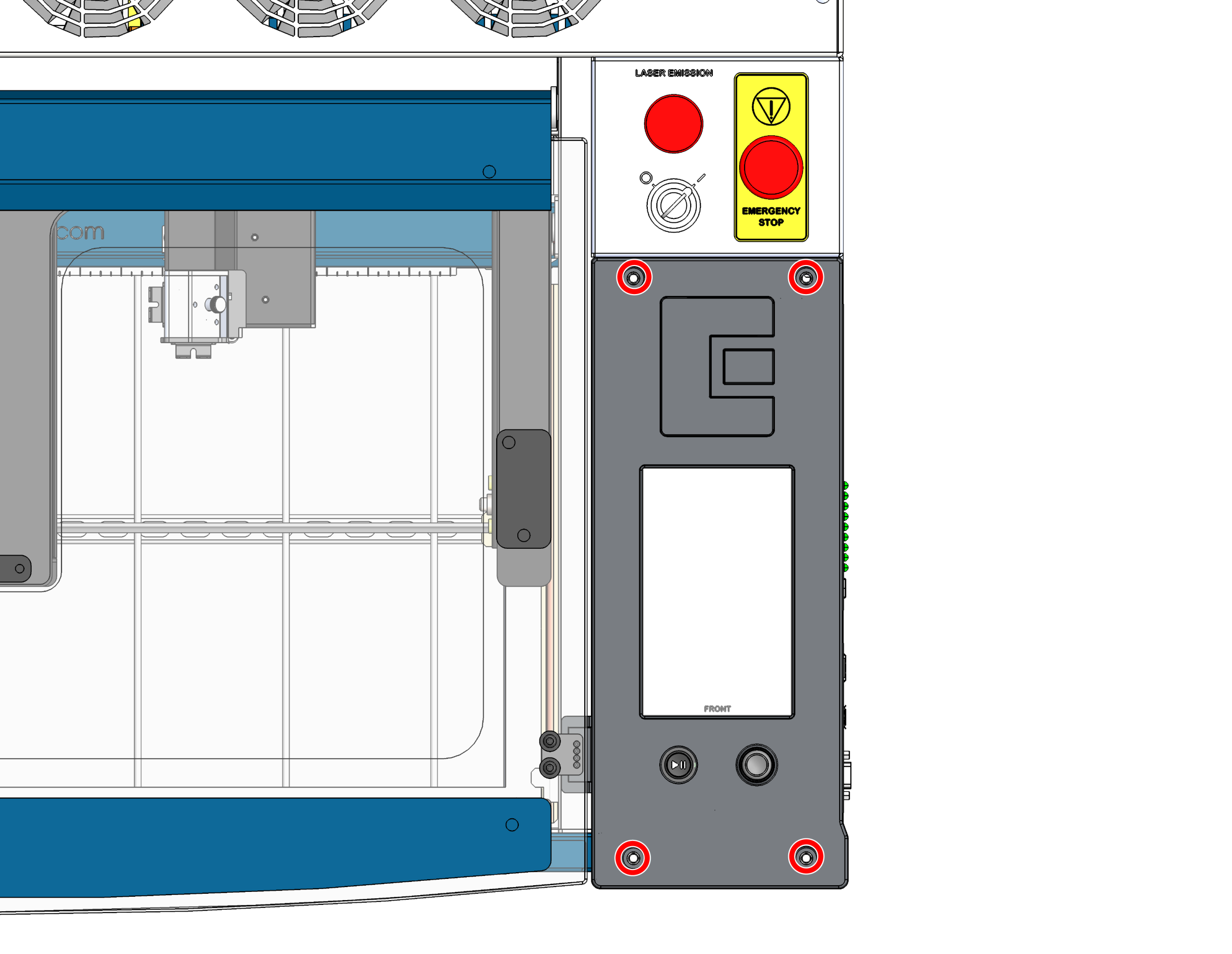
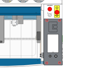
制御基板のネジを取り外す
コントロールボードをシャーシに固定している4本のネジを取り外してください。
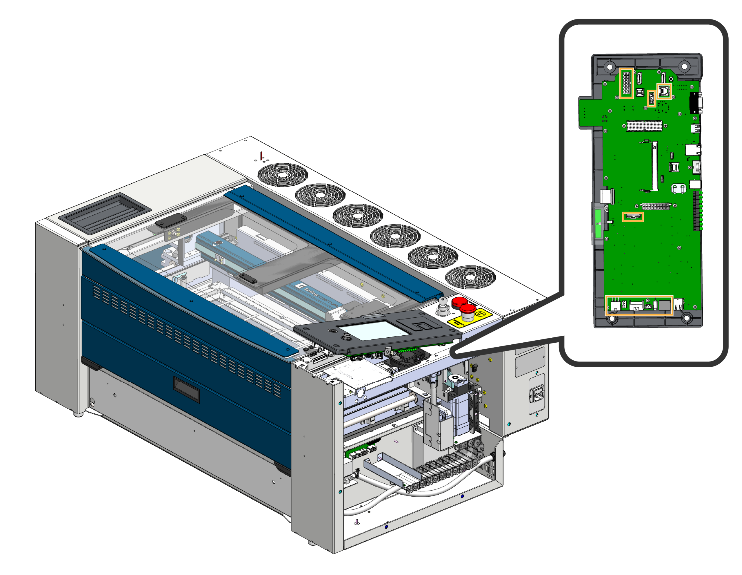
ハーネスの取り外し
制御基板の前部を慎重に上方に傾け、制御基板に接続されているワイヤーハーネスを取り外してください。
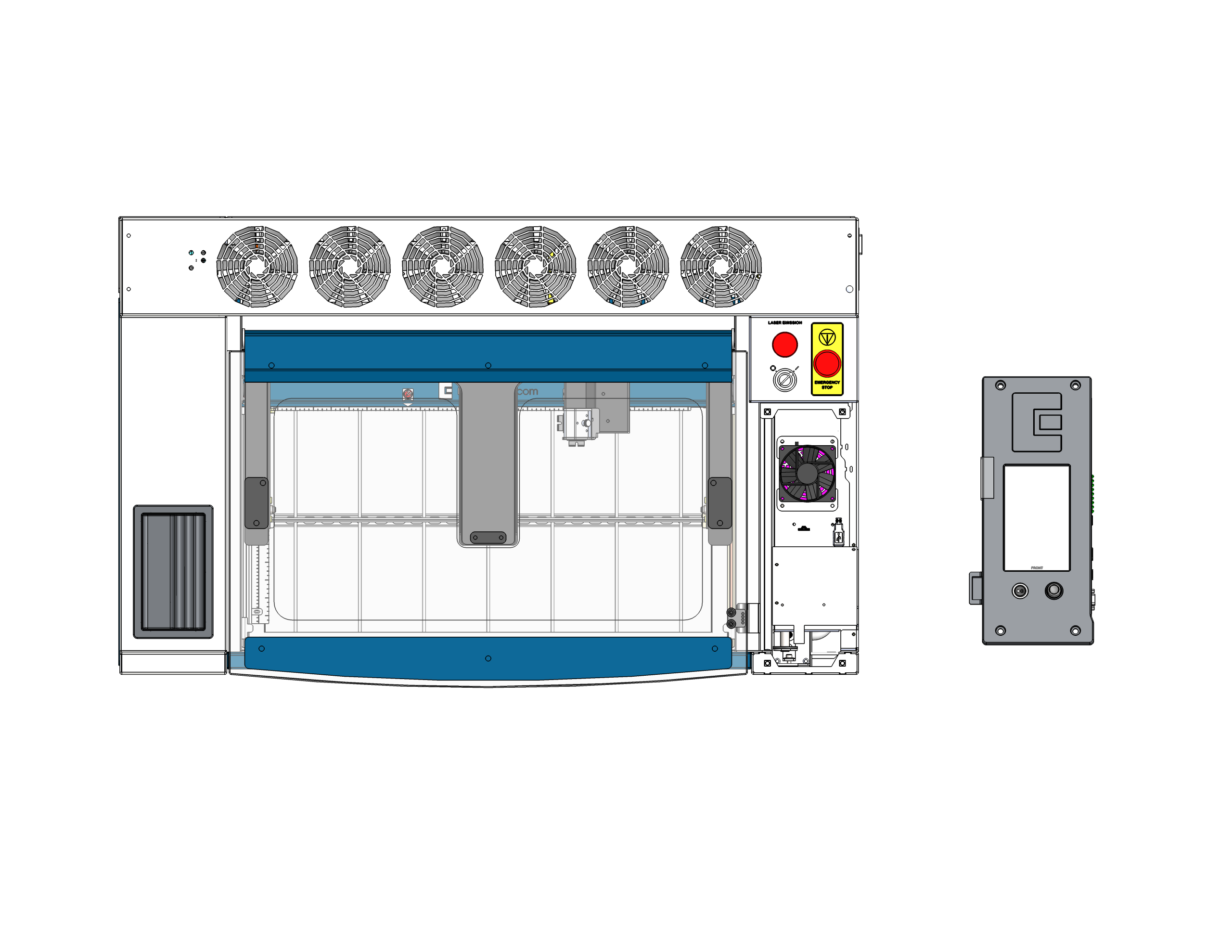
制御基板を取り外す
コントロールボードを本体から取り外し、完全に取り出してください。静電気の出ない安全な場所に、表面を下にして置いてください。重要:ボードの裏側で作業を行う際、ジョイスティックが押しつぶされたり破損したりしないよう、ジョイスティックが作業台の端からはみ出しているか、あるいは柔らかい素材の上に置かれていることを確認してください。
第2部:SDカードとコイン型電池の交換
コントロールボードを画面を下にして安定させておけば、ボード上に設置されているSDカードやコイン型電池に簡単にアクセスして交換することができます。
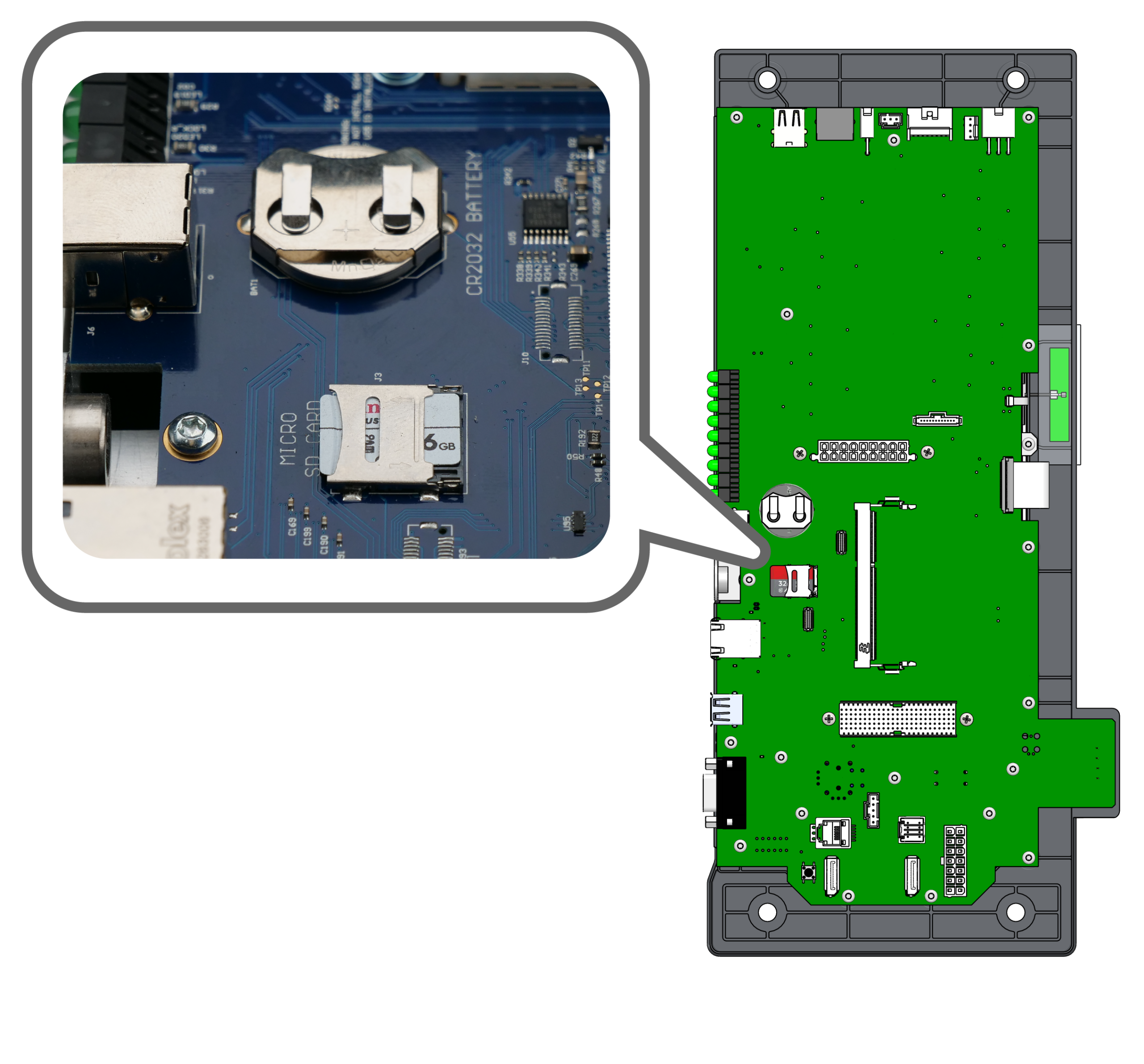
コンポーネントの位置を特定する
コントロールボードの背面にあるマイクロSDカードとCR2032コイン型電池の収納部を見つけてください。
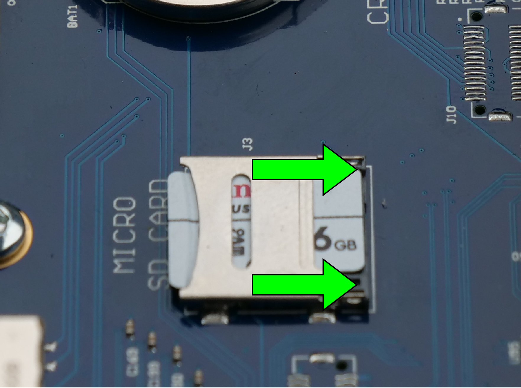
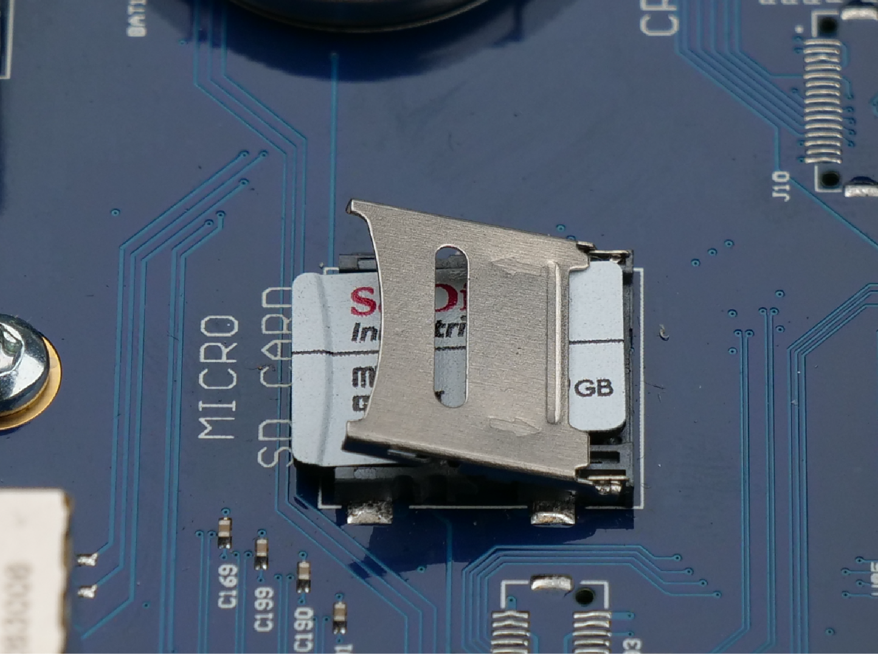
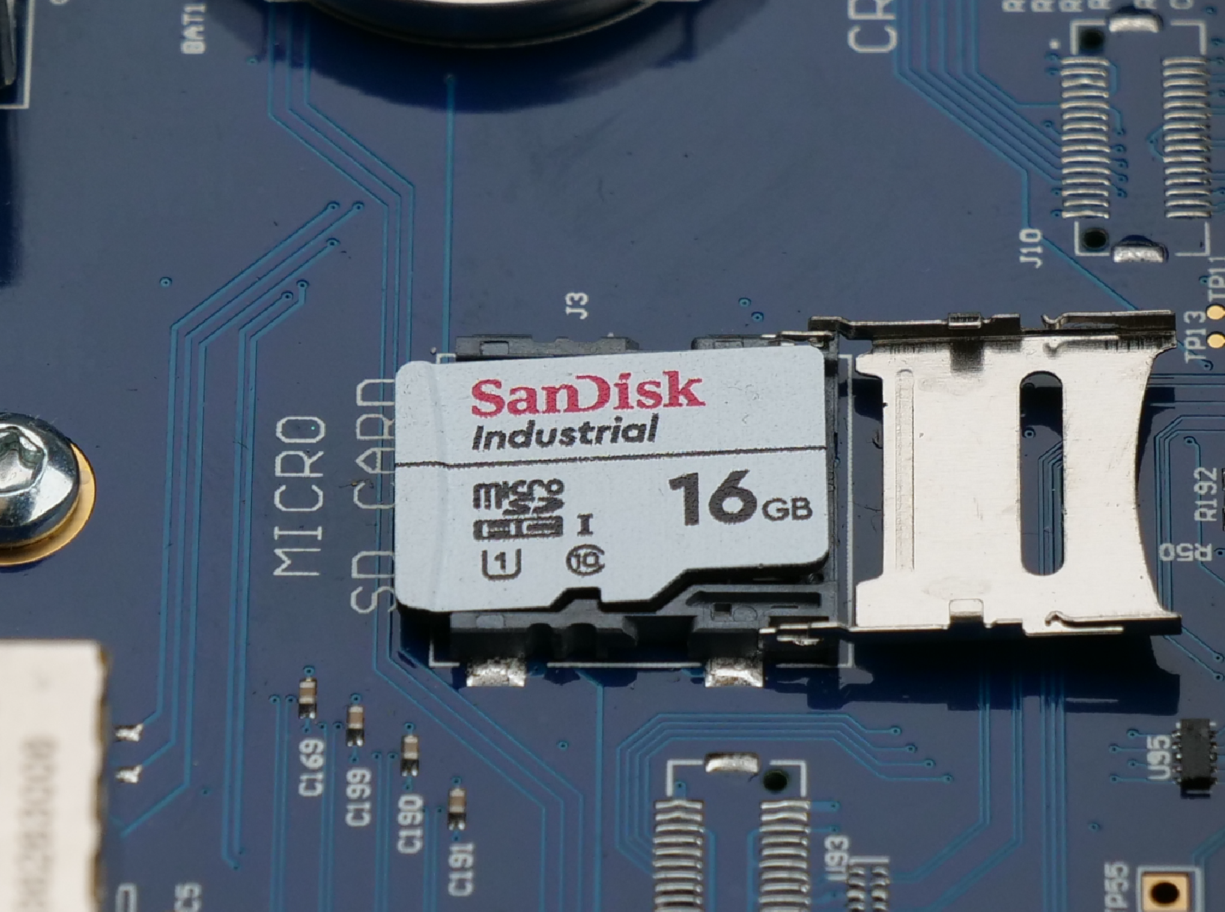
SDカードの交換
画像のタブをクリックして、交換手順をご覧ください:
- ロック解除:金属製の固定ラッチを内側(矢印の方向)にスライドさせて、ロックを解除してください。
- 開く:ロックされていない金属製のラッチを上方に持ち上げ、SDカードを取り出せるようにします。
- 交換方法:古いSDカードを取り外し、新しいSDカードを挿入してから、カバーを閉じて、ラッチを外側へスライドさせて固定します。
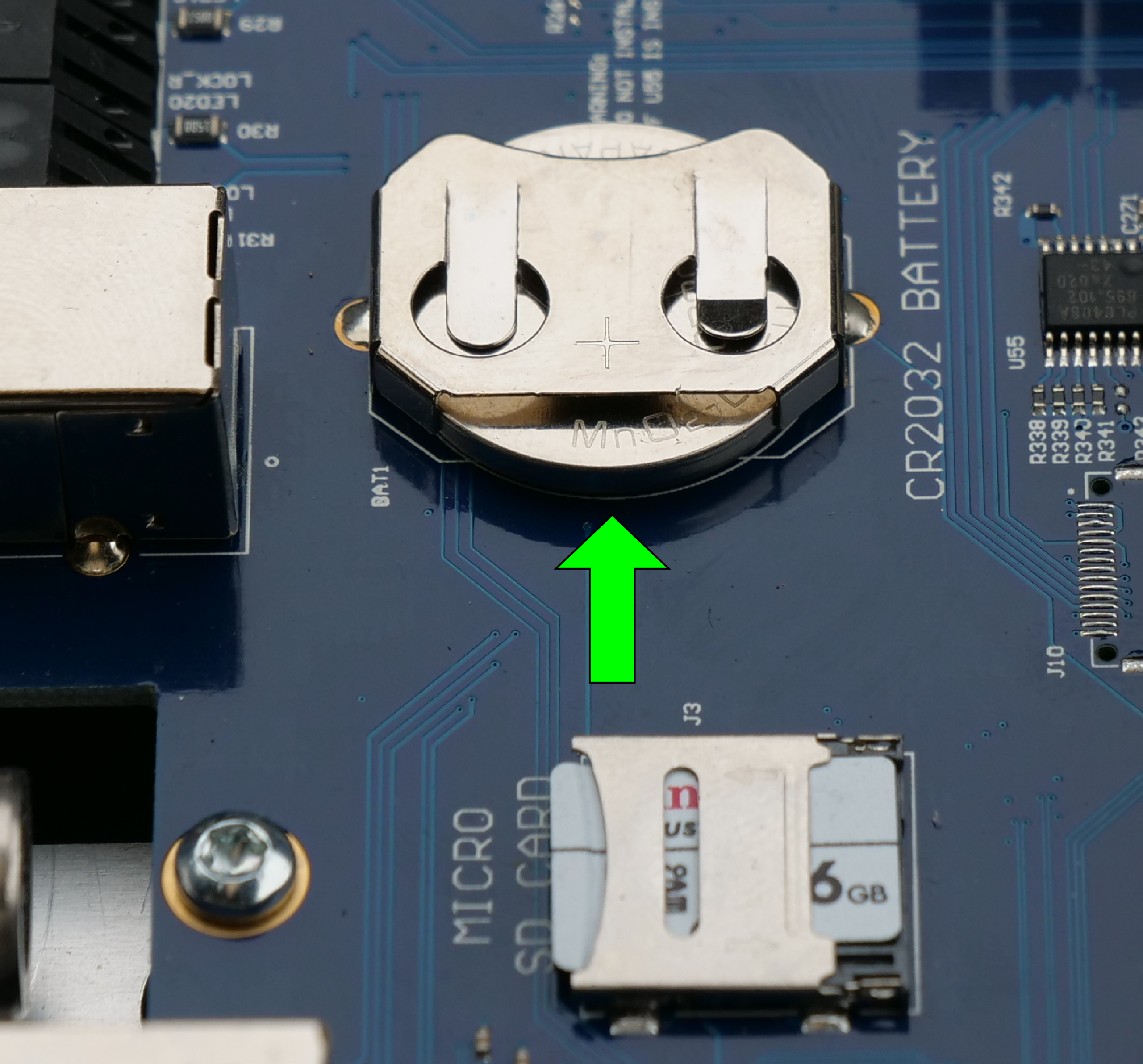
コイン型電池の交換
制御基板上のコイン型電池の収納部を見つけます。古い電池を固定クリップから慎重に引き抜きます。新しい電池を、プラス(+)側が上を向くように挿入します。
第3部:バックプレーンの交換
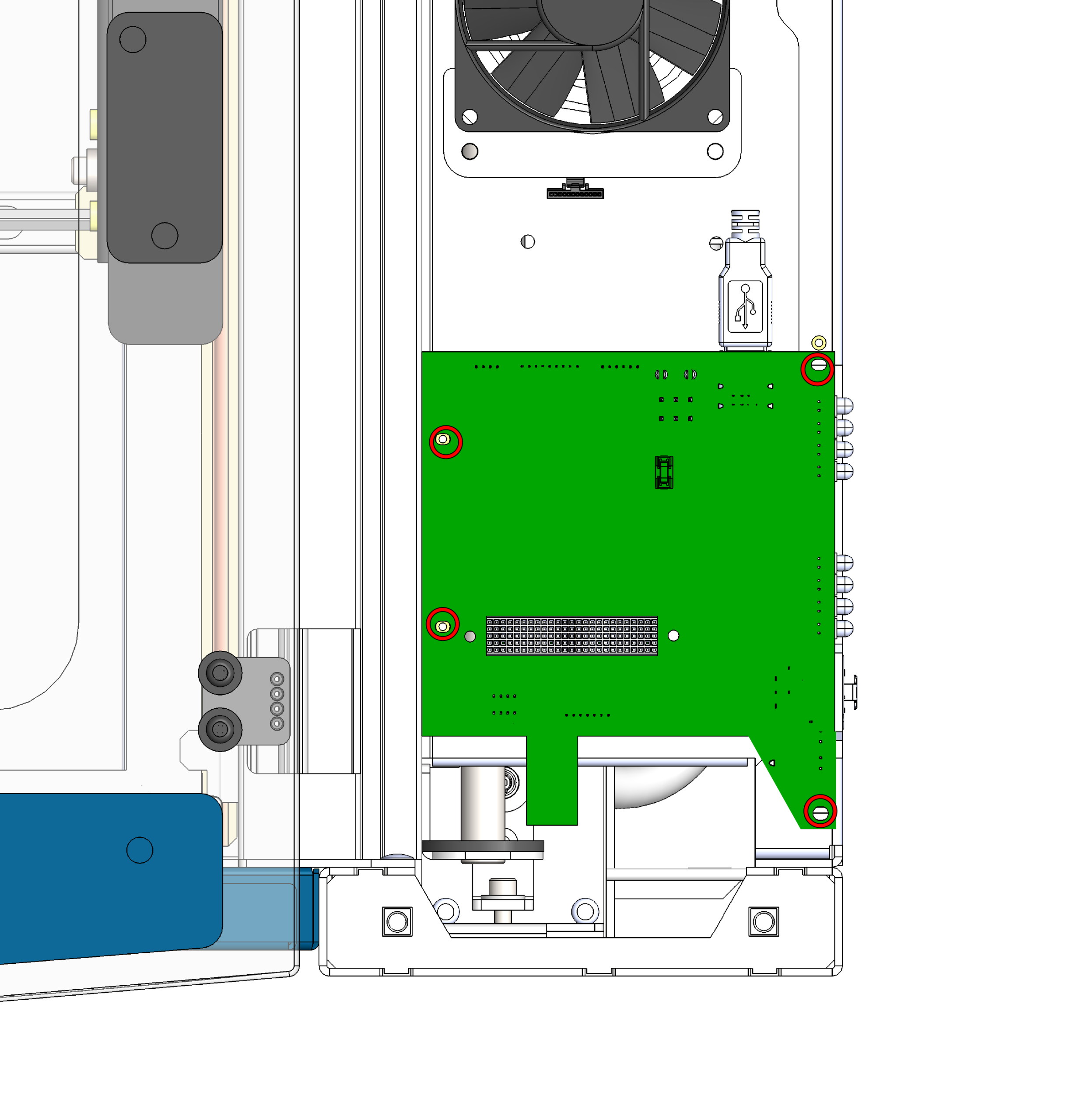
バックプレーンのネジを取り外す
コントロールボードの下に取り付けられているバックプレーンボードを見つけ、シャーシに固定している4本のネジを取り外してください。
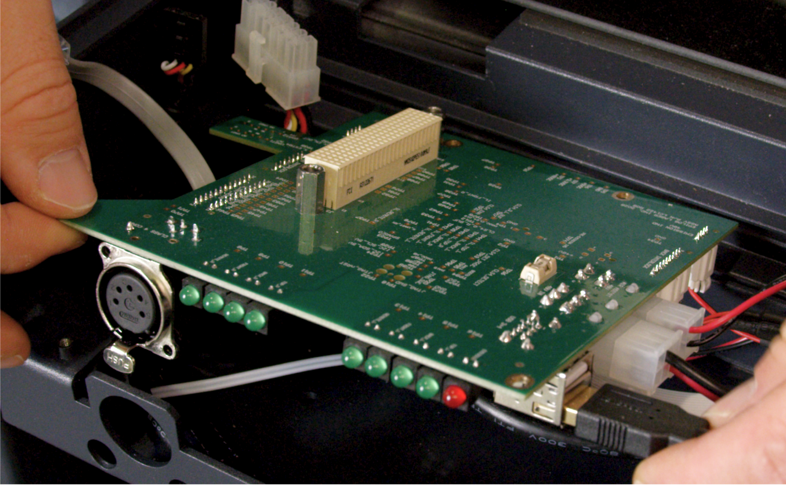
ケーブルを取り外す
基板のネジを外したら、基板に接続されているすべてのワイヤーハーネスとケーブルを慎重に外してください。すべての接続を外したら、バックプレーンを本体から取り出してください。
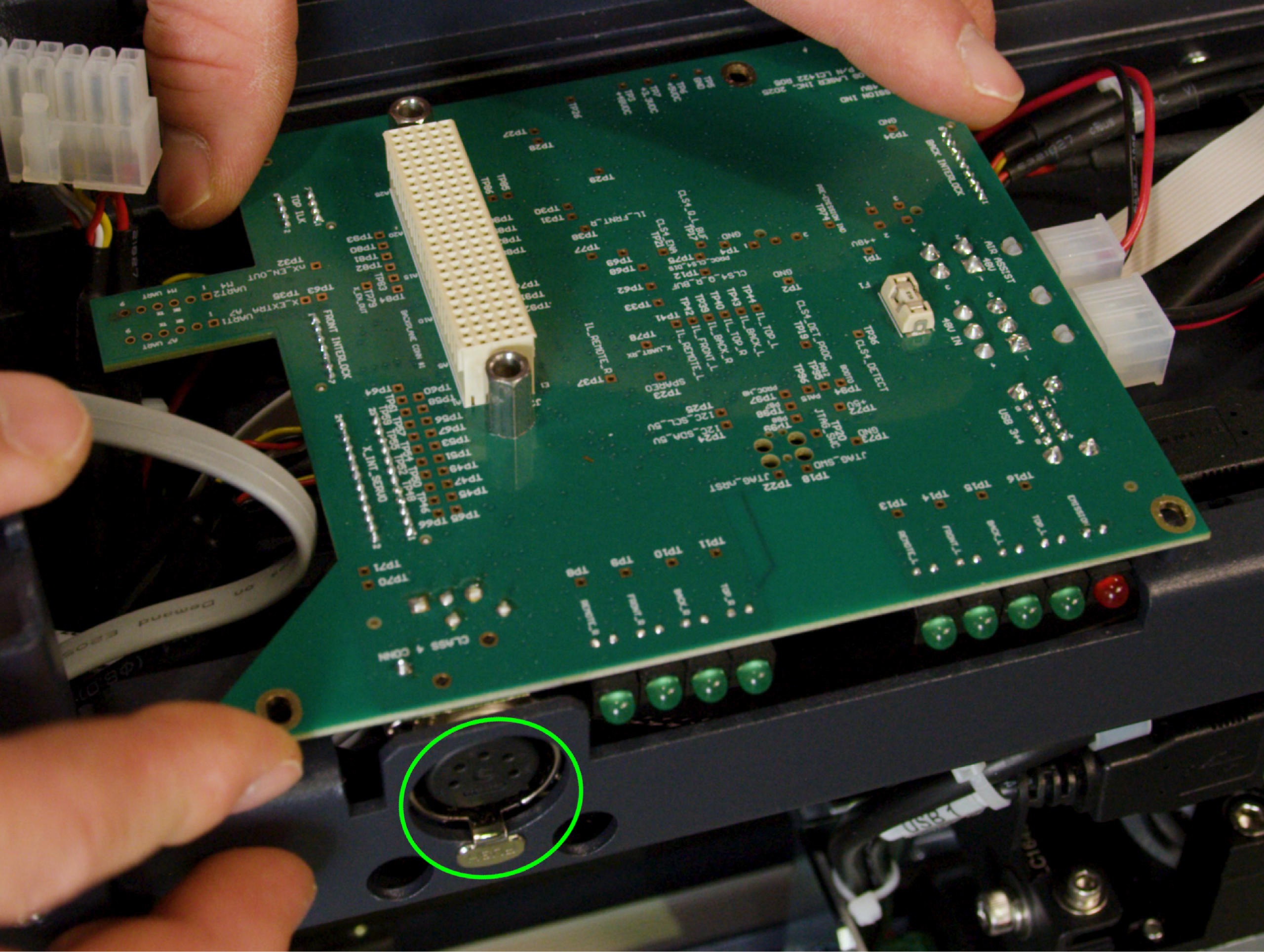
交換用バックプレーンの取り付け
まず、手順9で取り外したすべてのケーブルを再接続してください。すべてのケーブルがしっかりと接続されたら、基板の位置を合わせ、4本のネジを締め直してシャーシに取り付けてください。
重要:クラス4ドングルポートにはタブがあり、これをシャーシの切り欠きに合わせなければなりません。ポートや基板を損傷しないよう、ネジを締める前に、タブが切り欠みに正しく収まっていることを確認してください。
第4部:再組み立てと取り付け
リコネクト制御基板のハーネス
コントロールボード(新しいSDカードとバッテリーを取り付けた状態)を、取り付け場所に慎重に近づけ、ワイヤーハーネスをボードに再接続してください。
シート制御基板
コントロールボードをネジ穴の真上に位置合わせします。ボードが新しく取り付けられたバックプレーンにしっかりと固定されるよう、均等にしっかりと押し込んでください。
セキュア制御ボード
4本のネジを再度取り付け、しっかりと締め付けて、完全に所定の位置に収まった制御基板をシャーシに固定してください。
サイドパネルを交換する
本機の右側パネルを再度取り付け、しっかりと固定してください。
最終確認
本体を壁のコンセントに再び差し込み、電源を入れてください。タッチスクリーンが正常に起動し、本体が正常に初期化されることを確認してください。これにより、新しい基板、SDカード、バッテリー、およびバックプレーンがすべて正しく通信していることが示されます。