This guide provides step-by-step technical instructions for replacing the control board, SD card, coin battery, and backplane on your Ascent laser system.
Sicherheit geht vor: Vergewissern Sie sich, dass das Lasersystem vollständig ausgeschaltet und das Netzkabel aus der Steckdose gezogen ist, bevor Sie interne elektronische Bauteile berühren oder trennen. Berühren Sie keine freiliegenden Komponenten des Netzteils.
ESD Precaution: Always wear an anti-static wrist strap grounded to the machine’s bare metal chassis before handling the control board, backplane, or other sensitive electronic components to prevent electrostatic discharge damage.
Section 1: Control Board Removal
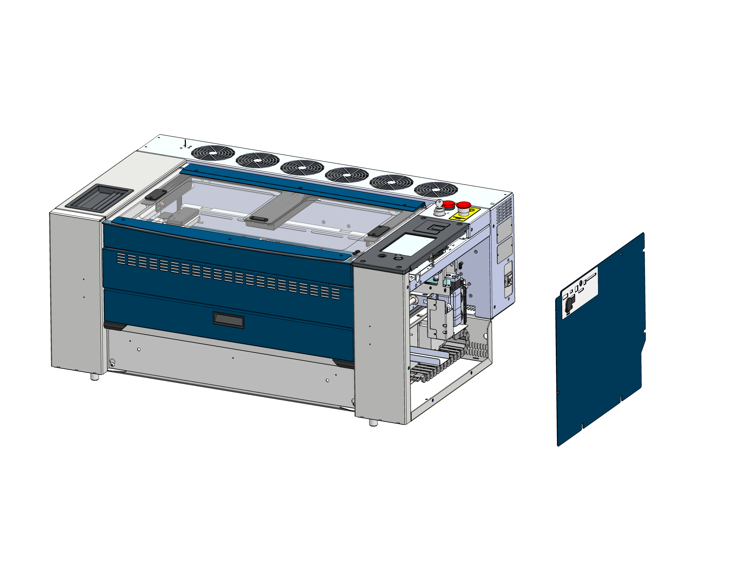
Seitenteil entfernen
Locate and remove the right side panel of the laser chassis to gain access to the electronics.
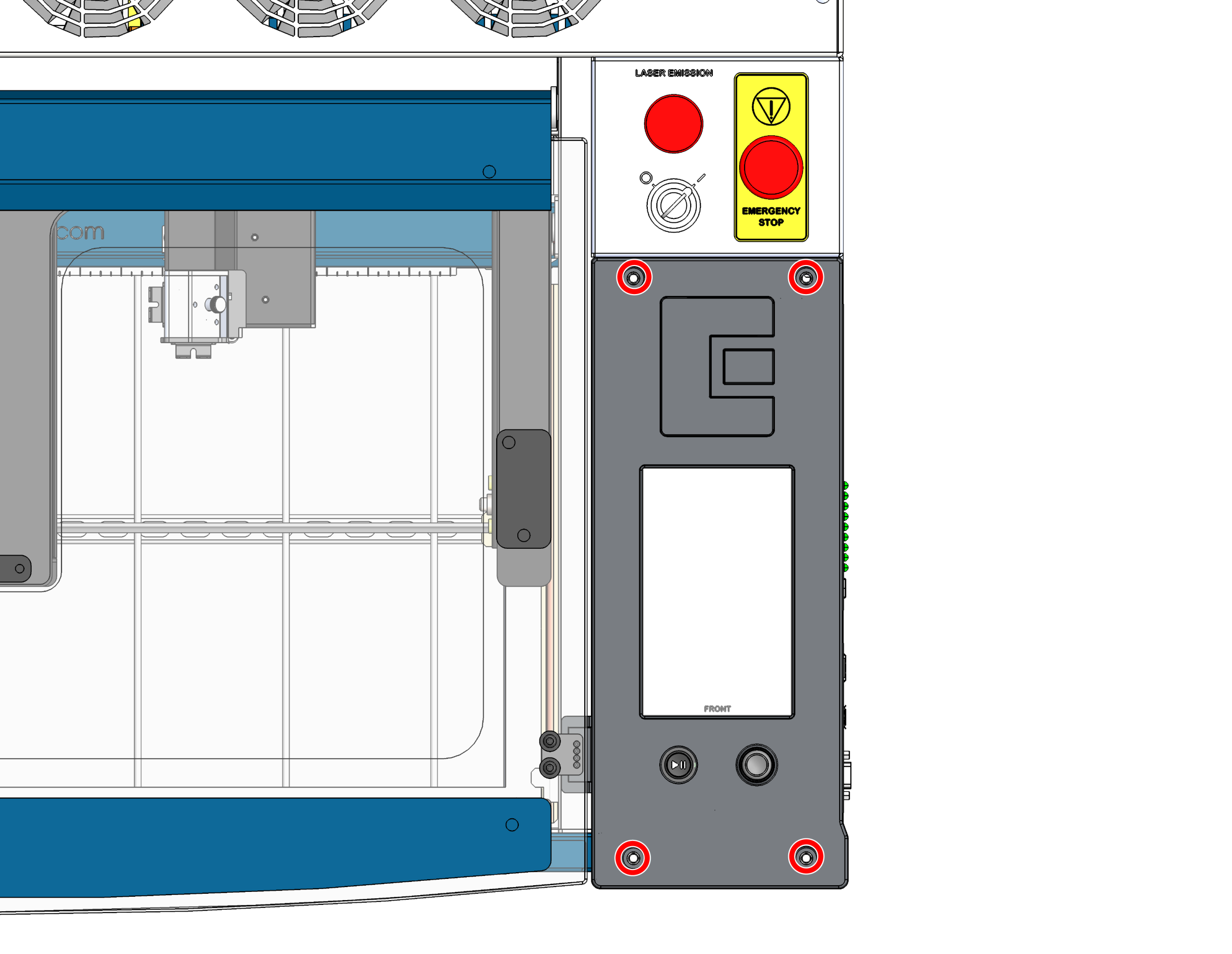
Schrauben der Steuerplatine entfernen
Lösen Sie die 4 Schrauben, mit denen die Steuerplatine am Gehäuse befestigt ist.
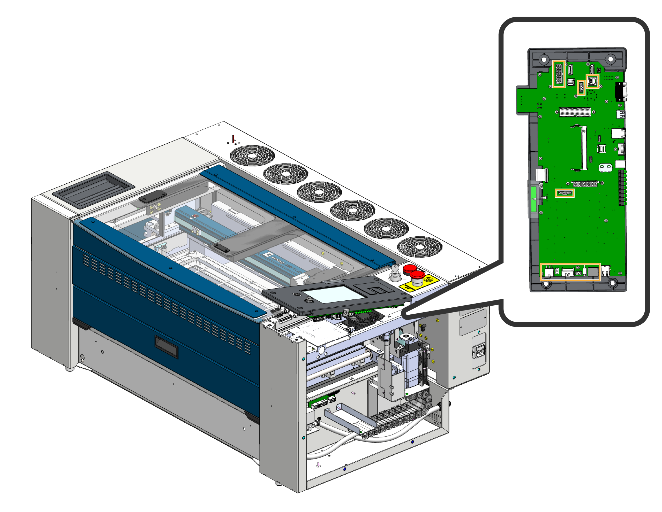
Kabelbaum abklemmen
Kippen Sie die Vorderseite der Steuerplatine vorsichtig nach oben und ziehen Sie die an der Steuerplatine angeschlossenen Kabelbäume ab.
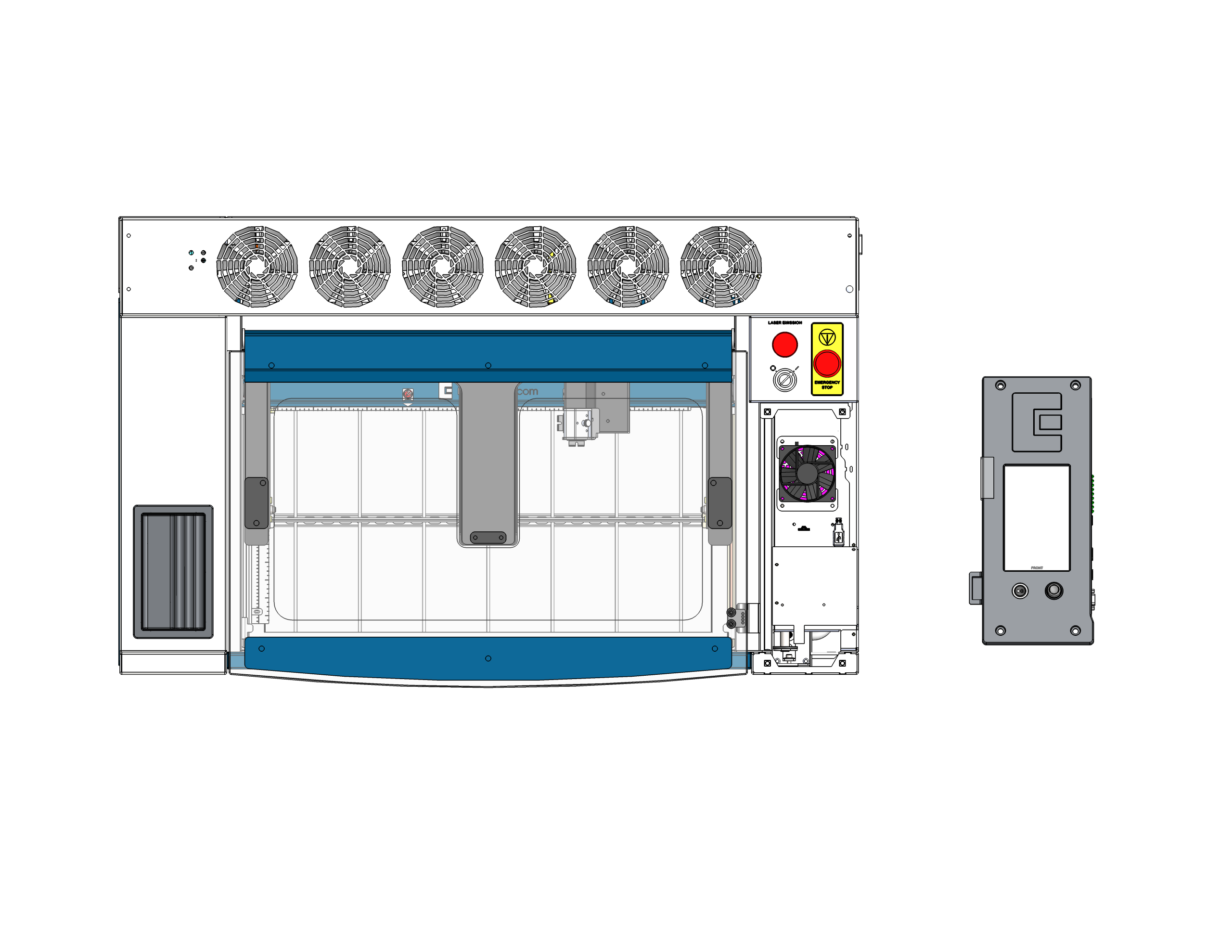
Steuerplatine entfernen
Unseat and fully remove the control board from the machine. Place it facedown on a safe, static-free surface. Important: Ensure the joystick is either hanging over the edge of the surface or placed on a soft material so that it is not crushed or damaged while you work on the back of the board.
Section 2: SD Card & Coin Battery Replacement
With the control board safely resting facedown, you can now easily access and replace the SD card and coin battery located on the board.
Replace SD Card
Locate the SD card slot on the control board. Gently press the metal holder towards the center of the control board to open the door. Remove the old SD card and insert the new one.
Replace Coin Battery
Locate the coin battery housing on the control board. Carefully slide the old battery out of its retaining clip. Insert the new battery with the positive (+) side facing up.
Section 3: Backplane Replacement
Remove Backplane Screws
Locate the backplane mounted to the left inside of the chassis. First, remove the 4 screws securing the backplane to the chassis to give yourself some slack.
Disconnect Cables
With the board unscrewed, carefully disconnect all wiring harnesses and cables plugged into it. Once everything is disconnected, lift the old backplane out of the machine.
Install New Backplane
Position the new backplane in the chassis. Systematically reconnect all the cables you removed in Step 8 first. Once all cables are securely plugged in, align the board and reinstall the 4 screws to mount it to the chassis.
Section 4: Reassembly & Installation
Reconnect Control Board Harnessing
Carefully bring the control board (with its new SD card and battery) close to the mounting area and reconnect the wiring harnesses to the board.
Sitzsteuerplatine
Center the control board directly above the screw holes. Press down evenly and firmly to ensure the board makes a solid connection to the newly installed backplane.
Sicherheitssteuerplatine
Setzen Sie die 4 Schrauben wieder ein und ziehen Sie sie fest, um die vollständig eingesetzte Steuerplatine am Gehäuse zu befestigen.
Seitenwand ersetzen
Setzen Sie die rechte Seitenwand des Geräts wieder ein und befestigen Sie sie.
Final Verification
Plug the machine back into the wall outlet and power it on. Verify that the touch screen boots up normally and the machine successfully initializes, indicating the new board, SD card, battery, and backplane are all communicating correctly.