Geschätzte Dauer: 30–45 Minuten • Schwierigkeitsgrad: Mittel
Diese Anleitung führt Sie durch den Austausch des Riemens der Tischachse (Z-Achse) bei den Lasersystemen Fusion Pro 32 und 48. Befolgen Sie diese Schritte, um eine korrekte Riemenführung, die richtige Spannung und eine gleichmäßige Bewegung der Z-Achse für präzise Gravuren sicherzustellen.
Entfernen des Riemens der Z-Achse
-
Power down and disconnect the engraver.
Turn off the engraver and unplug it from the power source. -
Remove access panels.
Remove the front and right side panels of the engraver.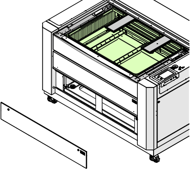
Bild 1: Frontblende entfernt.
-
Mark the motor location.
Use a pencil to mark the leading edge of the Z-Axis motor body on the chassis. This will help set proper belt tension during reinstallation.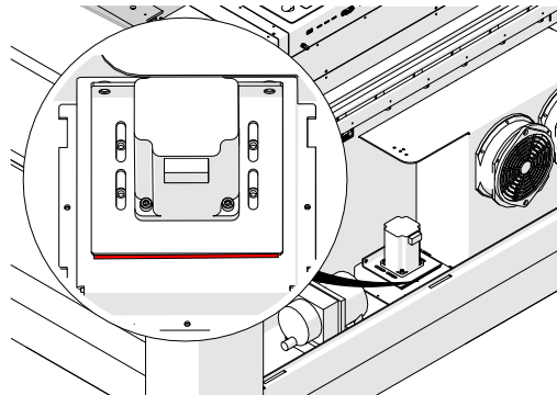
Bild 2: Markieren Sie die Position des Z-Achsen-Motors.
-
Trennen Sie den Kabelbaum des Z-Achsen-Motors.
-
Release belt tension.
Loosen, but do not remove, the two 7/64” Allen screws on the tensioner.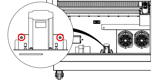
Bild 3: Spannschrauben lösen.
-
Remove motor mounting screws.
Loosen and remove the four 7/64” Allen screws securing the Z-Axis motor to the chassis.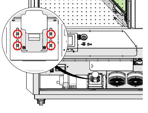
Bild 4: Entfernen Sie die Befestigungsschrauben des Motors.
-
Entfernen Sie den Z-Achsen-Motor.
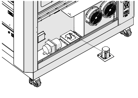
Bild 5: Z-Achsen-Motor entfernt.
-
Remove the Z-Axis belt.
Press the belt flat against the bottom of the chassis and slip it underneath each lead screw pulley.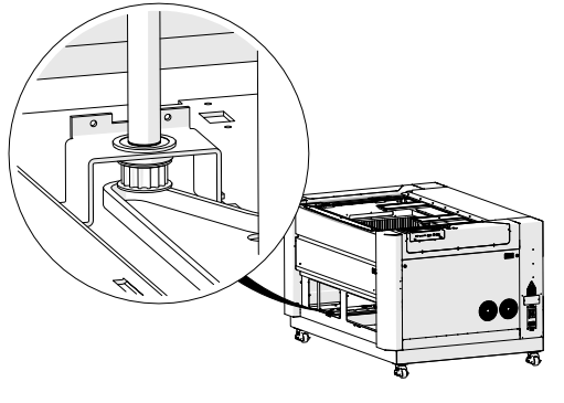
Bild 6: Z-Achsen-Riemen entfernt.
Einbau des Z-Achsen-Riemens
-
Place the Z-Axis belt in the chassis.
Press the belt flat against the bottom of the chassis and slip it underneath each lead screw pulley. Ensure the toothed side wraps around the pulleys correctly.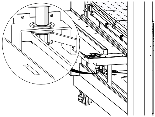
Bild 7: Z-Achsen-Riemen korrekt geführt.
-
Reinstall the Z-Axis motor.
Position the motor so the pulley fits inside the belt, and loosely install the four 7/64” Allen screws.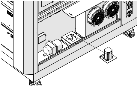
Bild 8: Z-Achsen-Motor installiert.
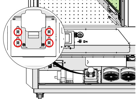
Abbildung 9: Befestigungsschrauben für den Motor.
-
Route belts on all lead screws.
Repeat for all four lead screw assemblies, ensuring proper routing.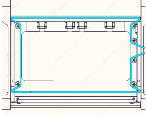
Abbildung 9: Riemenführung an allen Gewindespindeln.
-
Inspect belt placement.
Ensure the belt remains seated on all pulleys. Reposition if needed.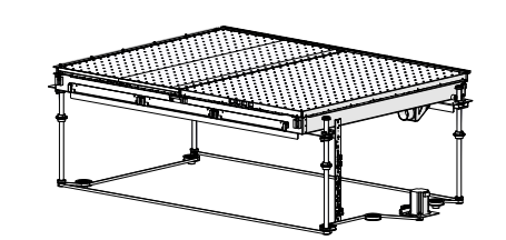
Bild 11: Überprüfen Sie die Position des Riemens.
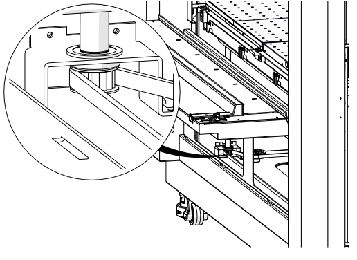
Bild 12: Riemenscheiben überprüfen.
-
Tension the belt.
Tighten the two 7/64” Allen screws on the tensioner until the motor aligns with the pencil mark made earlier.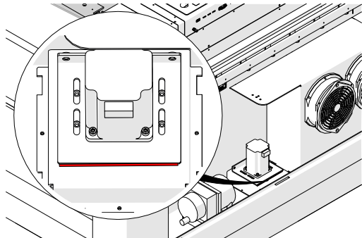
Bild 13: Riemenspannung eingestellt.
-
Secure the motor.
Tighten the four motor mounting screws.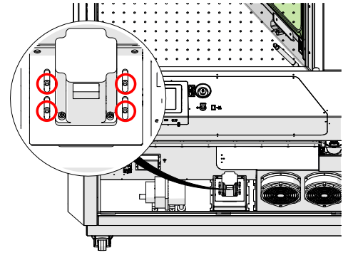
Bild 14: Motor gesichert.
-
Schließen Sie den Kabelbaum des Z-Achsen-Motors wieder an.
-
Reinstall all access panels.
Replace the front and right panels of the engraver.
Bild 16: Zugangsklappen wieder angebracht.