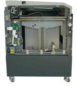
Dieses Verfahren beschreibt die erforderlichen Schritte zum Austausch des X-Achsen-Encoder-Lesegeräts an der Legend . Das X-Achsen-Encoder-Lesegerät ist eine wichtige Komponente für die genaue Bewegungserfassung der Objektivhalterung. Im Laufe der Zeit muss dieses Teil möglicherweise gewartet oder ausgetauscht werden, um die Präzision und den reibungslosen Betrieb der Maschine weiterhin zu gewährleisten. Wenn Sie die Anweisungen sorgfältig befolgen und die erforderlichen Werkzeuge verwenden, können Sie das X-Achsen-Encoder-Lesegerät sicher austauschen und die Leistung Ihrer Maschine wiederherstellen. Stellen Sie vor Beginn der Wartungsarbeiten immer sicher, dass das Gerät ausgeschaltet ist, um elektrische Gefahren zu vermeiden.
Entfernen des Encoder-Lesegeräts
-
Make sure power is turned off and power cord is unplugged from the
wall outlet. -
Open up the main door to gain access to the I-beam. The I-beam is
the long horizontal bar with a blue cover over it and has the
Epilog website written on top-right side of it. -
Use a #2 Phillips head screw driver to loosen up the 10 Phillips
head screws, 5 of them are located on the front and 5 are on the back of
the blue cover. These screws do not need to be removed completely
because the bottom of the blue cover is slotted. -
Once the blue cover is removed, locate the X-Axis encoder reader
board. This board travels along with the lens carriage assembly
when you manually slide it with the machine turned off.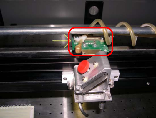
-
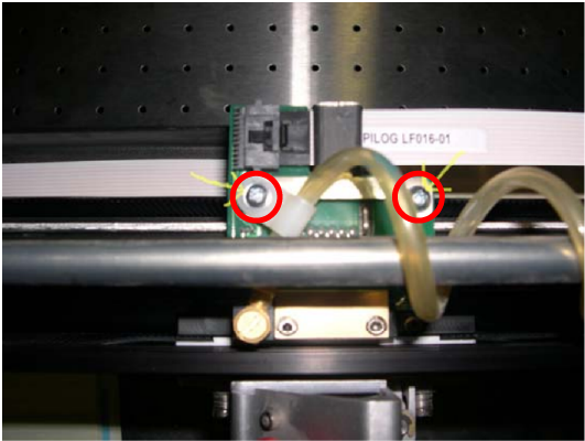
Entfernen Sie mit einem Kreuzschlitzschraubendreher Nr. 1 die beiden in der Abbildung unten eingekreisten Schrauben.
-
Once you have the bracket removed, disconnect the white ribbon
cable from the X-Axis encoder reader. This cable does not pull
straight out; you have to push down the plastic latch to release
the lock.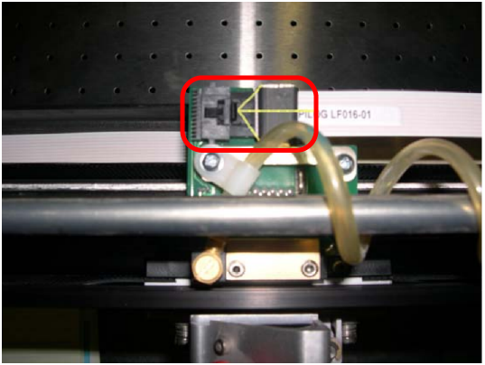
-
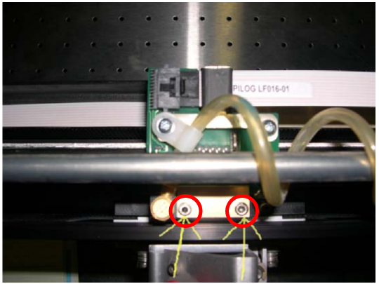
Verwenden Sie einen 3/32-Inbusschlüssel, um die beiden unten eingekreisten Inbusschrauben zu entfernen.
-
Check that the read head is positioned correctly. The read head is the
brown piece attached on the bottom side of the X-Axis encoder reader. You want the
encoder strip sitting in the middle of the read head. -
To install the new X-Axis encoder reader, simply reverse steps 7
through 2.