Geschätzte Dauer: 20–30 Minuten • Schwierigkeitsgrad: Mittel
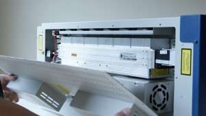
Diese Anleitung führt Sie durch den Prozess des Ausbaus und Einbaus der Laserbaugruppe in Ihrem Epilog Zing Lasersystem. Die Befolgung dieser Schritte gewährleistet die korrekte Ausrichtung, sichere Befestigung und optimale Leistung Ihres Gravursystems.
Laserentfernung
-
Power down and disconnect the machine.
Turn off the engraver and unplug it from the power source. -
Remove the left-hand side panel.
Remove the four Phillips screws securing the side panel: three on the side and one on the rear.
Bild 1: Seitenschrauben (Seitenansicht).

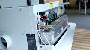
Bild 2: Schraube an der Seitenwand (Rückansicht).
-
Disconnect the laser power harness.
Located above and behind the laser assembly, press the lock and pull the connector toward you to disconnect.
Bild 3: Laserleistungs-Kabelbaum.
-
Disconnect the data cable.
Press the locking tab and remove the data cable from the laser assembly.
Bild 4: Laser-Datenkabel.
-
Remove the laser mounting plates.
The laser is held by two green mounting plates inside the engraving area on the left side. Loosen the four outer screws (Picture 5a) but do not remove the inner guide screw (Picture 5b). The screws will pop slightly but remain attached to the mount.
Abbildung 5: Äußere Schrauben an Montageplatten.

Abbildung 6: Innere Führungsschraube.
-
Remove the laser assembly.
Lift slightly and align the guide pin with the slot in the chassis. Slide the laser assembly toward the front and remove it from the machine.
Abbildung 7: Position der Lasermontageplatte.
Laserinstallation
-
Install the laser assembly.
Align the guide pins with the chassis holes, push the assembly against the side, and slide it forward until seated. -
Install the mounting plates.
Loosely install the four screws on each mounting plate. Once all screws are in place, tighten all eight screws securely. -
Schließen Sie das Datenkabel wieder an.

Bild 8: Datenkabel wieder angeschlossen.
-
Schließen Sie den Stromkabelbaum wieder an.

Bild 9: Stromkabel wieder angeschlossen.
-
Perform laser alignment.
After installation, perform a full laser alignment as described in the Epilog Technical Note: Zing Laser Alignment.