Tiempo estimado: 15-20 minutos • Nivel: principiante
Este procedimiento le guiará a través del proceso de extracción y sustitución del conjunto del émbolo de enfoque automático (AFP) de su sistema láser. El AFP es un componente crítico que se utiliza para ajustar automáticamente la distancia de enfoque correcta entre el cabezal láser y la superficie del material. La sustitución de un AFP dañado o defectuoso garantiza una calidad de grabado constante y un rendimiento fiable del enfoque automático.
Eliminación de AFP
-
Power down and disconnect the machine.
Turn off the engraver and unplug it from the power source. -
Remove the carriage cover.
Loosen and remove the nine (9) Torx screws securing the carriage assembly cover, then lift the cover off to expose the AFP assembly.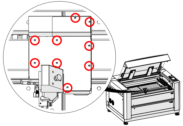
Imagen 1: Ubicación de los tornillos Torx que fijan la cubierta del carro.
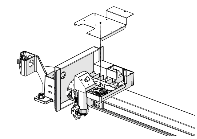
Imagen 2: Se ha retirado la cubierta del carro, dejando al descubierto el conjunto AFP.
-
Remove the AFP magnet block.
Using a 5/64” Allen wrench, loosen and remove the one (1) screw securing the AFP magnet block.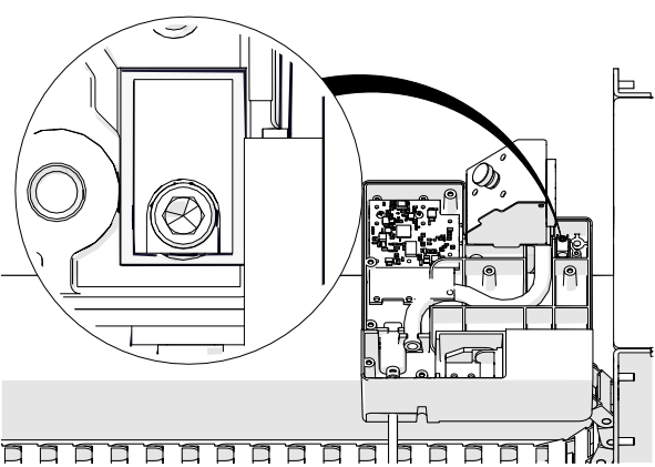
Imagen 3: Retirada del tornillo del bloque magnético AFP.
-
Remove the AFP assembly.
Pull the AFP shaft downward and lift the AFP magnet block upward to remove the AFP assembly completely.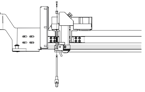
Imagen 4: Extracción del conjunto AFP del carro.
Instalación de AFP
-
Install the AFP assembly.
Insert the AFP shaft into the opening at the bottom of the carriage assembly. Position the AFP magnet block on top of the shaft and secure it with the one (1) 5/64” Allen screw.
Imagen 5: Instalación del conjunto AFP.
-
Orient the magnet correctly.
Ensure the magnet faces the back of the engraver before tightening the screw.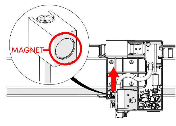
Imagen 6: Orientación correcta del imán.
Importante: Una orientación incorrecta del imán impedirá que el AFP vuelva a su posición de reposo.
Prueba de la AFP
-
Test the plunger movement.
Press up on the AFP and release it. The plunger should quickly return to its resting position. If it does not, verify the magnet block is seated correctly and not crooked.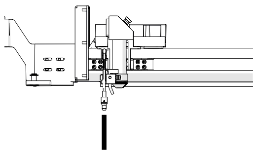
Imagen 7: Prueba del movimiento del émbolo AFP.
-
Power on the engraver.
Reconnect the power cable and turn the engraver back on. -
Open the Settings menu.
On the display panel, press the gear icon in the upper-right corner to open the Settings menu.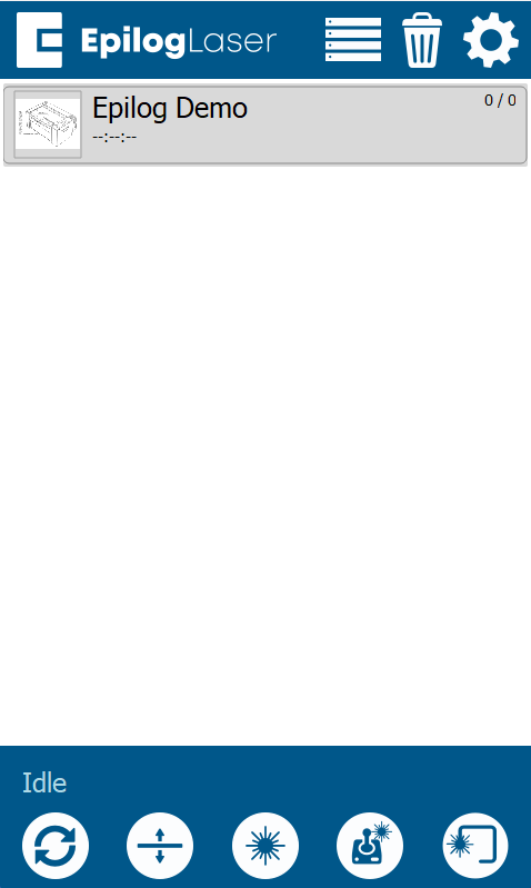
Imagen 8: Acceso al menú Configuración.
-
Access Focus Settings.
Press“Focus” on the display to access the Focus Menu.
Imagen 9: Accediendo a los ajustes de enfoque.
-
Run the AFP sensor test.
Turn Calibration Mode ON by pressing the “plus” symbol. Then select Table. Press up on the AFP and confirm that the “Plunger” indicator box on the right side of the screen activates. This ensures the sensor is functioning correctly.
Imagen 10: Menú de comandos de enfoque que muestra la selección de tabla.
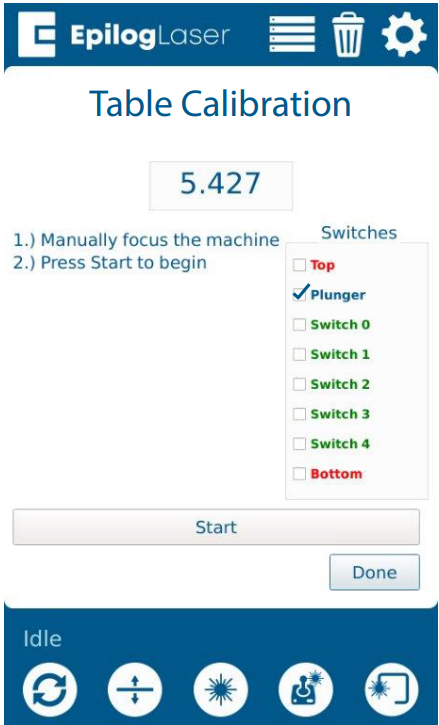
Imagen 11: Pulsar el AFP para comprobar la activación del sensor.
Montaje final
-
Reinstall the carriage cover.
Place the carriage cover back onto the assembly.
Imagen 11: Volver a colocar la cubierta del carro.
-
Secure the cover.
Install and tighten the nine (9) Torx screws that hold the carriage cover in place.
Imagen 12: Fijación de la cubierta del carro con tornillos Torx.