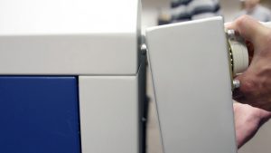
SD Card and Coin Battery Replacement
SAFETY WARNING
Turn off the engraver and disconnect it from all power sources and interface cables before performing maintenance. Always wear an anti-static wrist strap attached to a bare metal surface on the machine to prevent electrostatic discharge. Use caution when removing and installing the control module to prevent damage to flex cables, delicate display hardware, or backplane multi-pin connectors. Do not power off the engraver while performing peripheral updates.
Procedure Steps

Prepare Machine for Control Module Removal
Turn off the engraver, disconnect it from the power source, and unplug all connection cables (USB, Ethernet, fan control, etc.). Remove the right panel of the engraver. Place the anti-static wrist strap around your wrist and attach the clamp to a bare metal surface on the machine.

Unfasten Control Module Screws
Loosen and remove the four (4) 5/32″ Allen screws securing the control module. Note that two (2) of the screws are longer than the others; these longer screws secure the top side of the control module to the rear mounting locations.

Disconnect Front Wiring Harnesses
Grasp the bottom of the display shroud and gently raise the bottom of the control module upwards to gain access to the underside electrical harnesses. Disconnect the four (4) electrical harnesses located at the front of the module.

Disconnect Flex Cable and Rear Harnesses
Continue raising the control module upwards to gain access to the middle flex cable and disconnect it. Then disconnect the seven (7) electrical harnesses located at the rear of the module. Remove the control module completely and place it face-down on a soft surface to avoid damage.

Remplacer la carte SD
Locate the SD card holder on the underside of the control module. Slide the retention latch down to unlock it and lift out the old SD card. Insert the new SD card with the exposed copper terminals facing the control board, then press down and slide the retention latch up to lock it in place.

Remplacer la pile bouton
Locate the coin battery holder on the underside of the control module and slide out the old battery. Insert the new 3V lithium battery with the positive (+) terminal facing up and the negative (-) terminal facing the circuit board.

Reinstall Control Module
Position the top of the control module near the rear mounting location while wearing your anti-static strap. Reconnect the seven (7) rear electrical harnesses, the middle flex cable, and the four (4) front electrical harnesses (ensure the DisplayPort connector for the X-axis drive/fiber source is plugged into the correct receptacle). Secure with the four (4) 5/32″ Allen screws, placing the two longer screws in the rear.

Program the New SD Card
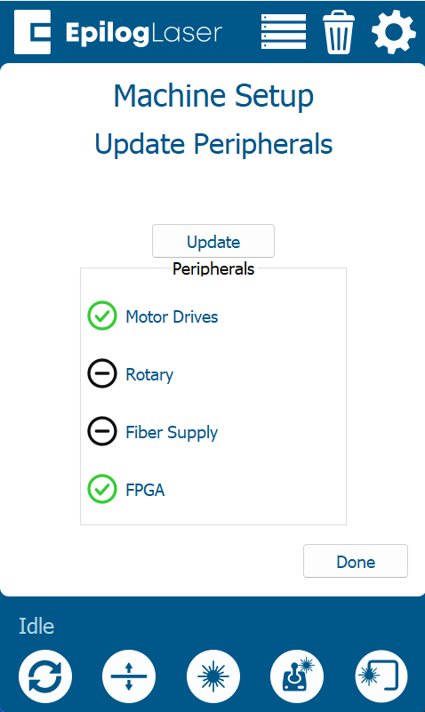
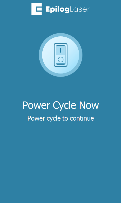
Reconnect power and turn on the engraver. On the display panel, tap the gear icon (Settings) > Program to enter the Peripheral Update menu. Select all available components, press Update, and allow the update process to finish without powering off the machine. Power cycle the engraver when prompted.
SD Card and Coin Battery Replacement
SAFETY WARNING
Turn off the engraver and disconnect it from all power sources and interface cables before performing maintenance. Always wear an anti-static wrist strap attached to a bare metal surface on the machine to prevent electrostatic discharge. Do not power off the engraver while performing peripheral updates.
Procedure Steps
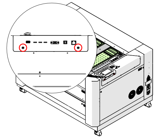
Prepare Machine & Unfasten Screws
Turn off the engraver, disconnect it from the power source, and unplug all connection cables (USB, Ethernet, fan control, etc.). Put on the anti-static strap and attach it to a bare metal surface on the machine. Loosen the two Phillips screws on the control module.
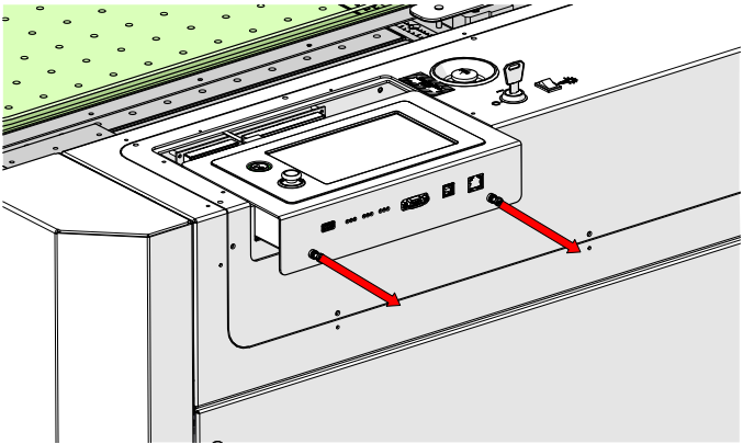
Remove the Control Module
Grip the screws and gently pull the module straight out, keeping it parallel with the engraver. Note: The control module slides into tracks on both sides of the housing. Do not lift or tilt the module during removal; slide it straight out.
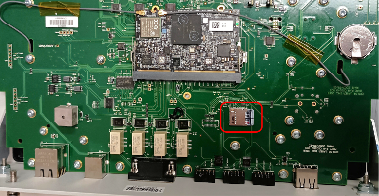
Locate the SD Card
Place the control module face-down on a soft surface to avoid damaging the display. Locate the SD card holder on the underside of the module.
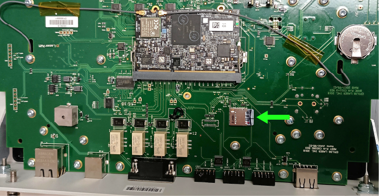
Replace the SD Card
Slide the old SD card out of the holder. Insert the new SD card with the copper terminals facing the control board.
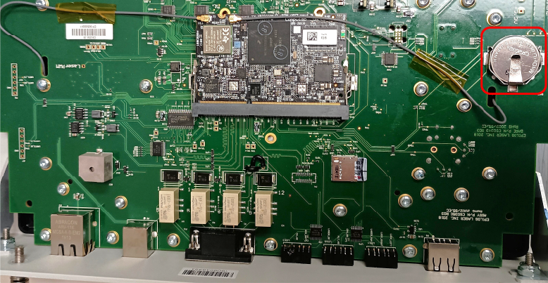
Locate the Coin Battery
While the control module is still face-down on the soft surface, locate the coin battery holder on the underside of the board.

Replace the Coin Battery
Remove the old battery. Insert the new 3V lithium coin cell battery with the positive (+) terminal facing away from the control board.
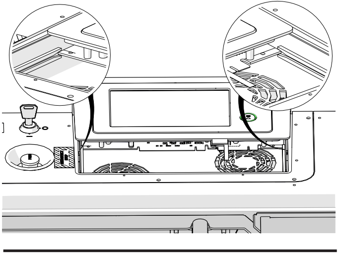
Align the Control Module
While wearing your anti-static strap, return to the machine and align the control module with the left and right housing tracks.
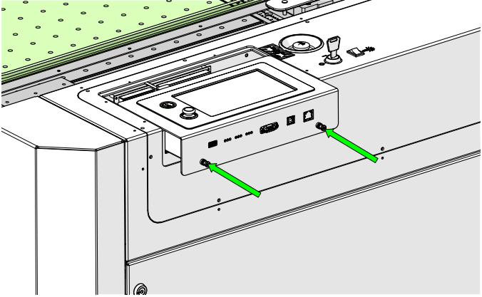
Reinstall & Secure the Module
Slide the control module back into place gently, ensuring it stays parallel with the top of the engraver. Once seated, tighten the two Phillips screws to secure it. Reconnect the power cord and turn on the engraver.
Program the New SD Card
(Skip this section if running firmware 1.1.2.x or later). At the display panel, press the gear icon in the upper-right corner to open the Settings menu. Press Update, then press Program Peripherals. Select All Available Peripherals and press Update.
Complete Update & Power Cycle
Allow the engraver to complete the update process. Warning: Do not power off the engraver during the update. The screen may go dark temporarily—this is normal. When prompted, power cycle the engraver to complete the update.