Durée estimée : 30 à 45 minutes • Niveau : intermédiaire
Cette procédure vous guide tout au long du processus de démontage et d'installation de la courroie de la table (axe Z) sur les systèmes laser Fusion Pro 32 et 48. Suivez ces étapes pour garantir un acheminement correct de la courroie, une tension adéquate et un mouvement fluide de l'axe Z pour une gravure précise.
Retrait de la courroie de l'axe Z
-
Power down and disconnect the engraver.
Turn off the engraver and unplug it from the power source. -
Remove access panels.
Remove the front and right side panels of the engraver.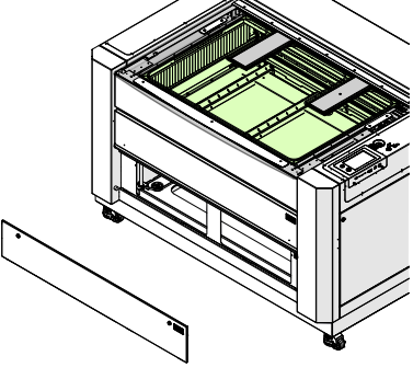
Image 1 : Panneau avant retiré.
-
Mark the motor location.
Use a pencil to mark the leading edge of the Z-Axis motor body on the chassis. This will help set proper belt tension during reinstallation.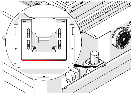
Image 2 : Marquez la position du moteur de l'axe Z.
-
Débranchez le faisceau du moteur de l'axe Z.
-
Release belt tension.
Loosen, but do not remove, the two 7/64” Allen screws on the tensioner.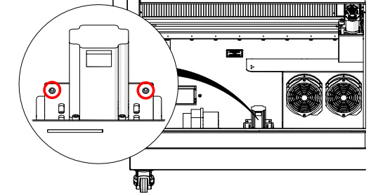
Image 3 : Desserrer les vis du tendeur.
-
Remove motor mounting screws.
Loosen and remove the four 7/64” Allen screws securing the Z-Axis motor to the chassis.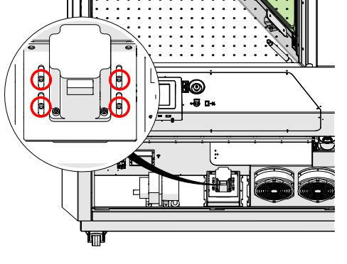
Image 4 : Retirez les vis de fixation du moteur.
-
Retirez le moteur de l'axe Z.
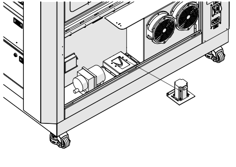
Image 5 : Moteur de l'axe Z retiré.
-
Remove the Z-Axis belt.
Press the belt flat against the bottom of the chassis and slip it underneath each lead screw pulley.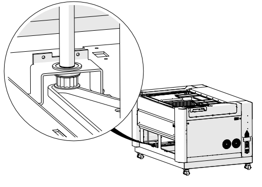
Image 6 : Courroie de l'axe Z retirée.
Installation de la courroie de l'axe Z
-
Place the Z-Axis belt in the chassis.
Press the belt flat against the bottom of the chassis and slip it underneath each lead screw pulley. Ensure the toothed side wraps around the pulleys correctly.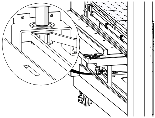
Image 7 : Courroie de l'axe Z correctement acheminée.
-
Reinstall the Z-Axis motor.
Position the motor so the pulley fits inside the belt, and loosely install the four 7/64” Allen screws.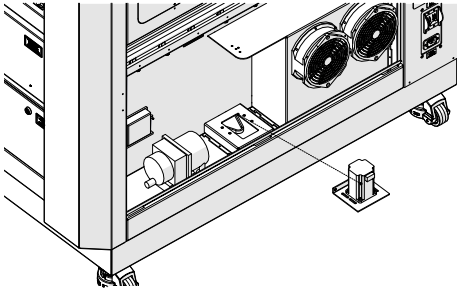
Image 8 : Moteur de l'axe Z installé.
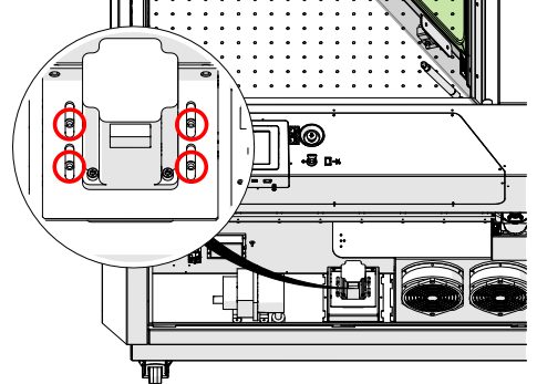
Image 9 : Vis de fixation du moteur.
-
Route belts on all lead screws.
Repeat for all four lead screw assemblies, ensuring proper routing.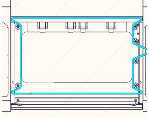
Image 9 : Acheminement de la courroie sur toutes les vis sans fin.
-
Inspect belt placement.
Ensure the belt remains seated on all pulleys. Reposition if needed.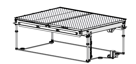
Image 11 : Vérifiez le positionnement de la courroie.
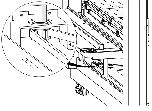
Image 12 : Inspectez les poulies.
-
Tension the belt.
Tighten the two 7/64” Allen screws on the tensioner until the motor aligns with the pencil mark made earlier.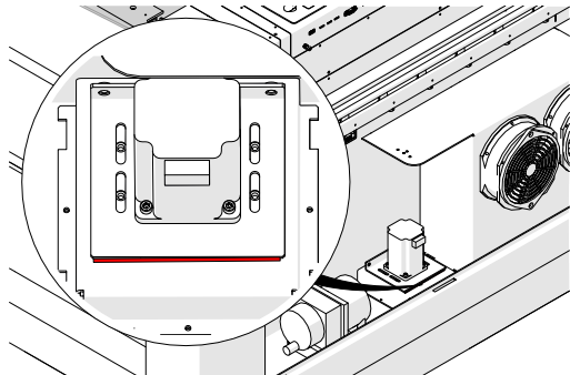
Image 13 : Tension de la courroie ajustée.
-
Secure the motor.
Tighten the four motor mounting screws.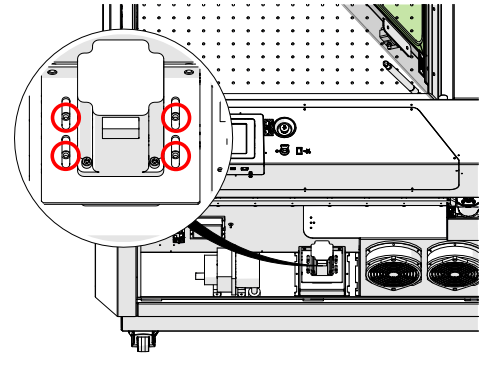
Image 14 : Moteur fixé.
-
Rebranchez le faisceau du moteur de l'axe Z.
-
Reinstall all access panels.
Replace the front and right panels of the engraver.
Image 16 : Panneaux d'accès réinstallés.