Durée estimée : 15 à 20 minutes • Niveau : débutant
Cette procédure vous guidera tout au long du processus de démontage et de remplacement du piston d'autofocus (AFP) de votre système laser. L'AFP est un composant essentiel utilisé pour régler automatiquement la distance de mise au point correcte entre la tête laser et la surface du matériau. Le remplacement d'un AFP endommagé ou défectueux garantit une qualité de gravure constante et des performances d'autofocus fiables.
Suppression de l'AFP
-
Power down and disconnect the machine.
Turn off the engraver and unplug it from the power source. -
Remove the carriage cover.
Loosen and remove the nine (9) Torx screws securing the carriage assembly cover, then lift the cover off to expose the AFP assembly.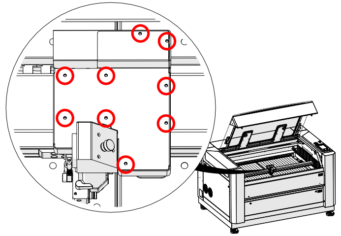
Image 1 : Emplacements des vis Torx fixant le couvercle du chariot.
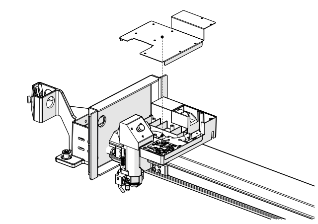
Image 2 : Couverture du chariot retirée, exposant l'ensemble AFP.
-
Remove the AFP magnet block.
Using a 5/64” Allen wrench, loosen and remove the one (1) screw securing the AFP magnet block.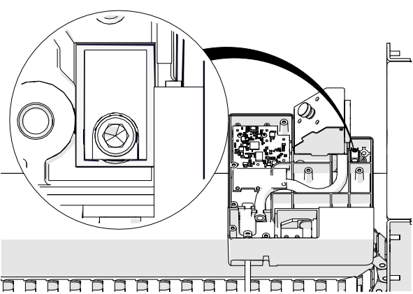
Image 3 : Retrait de la vis du bloc magnétique AFP.
-
Remove the AFP assembly.
Pull the AFP shaft downward and lift the AFP magnet block upward to remove the AFP assembly completely.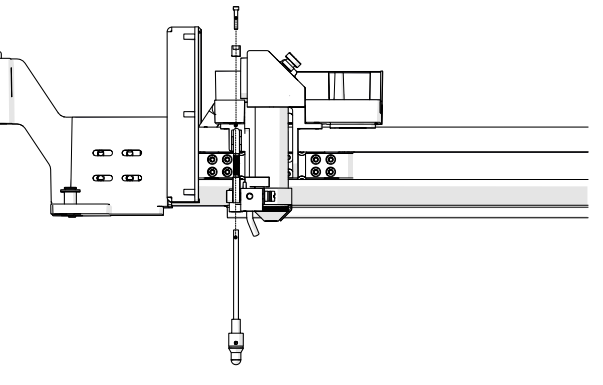
Image 4 : Retrait de l'ensemble AFP du chariot.
Installation AFP
-
Install the AFP assembly.
Insert the AFP shaft into the opening at the bottom of the carriage assembly. Position the AFP magnet block on top of the shaft and secure it with the one (1) 5/64” Allen screw.
Image 5 : Installation de l'ensemble AFP.
-
Orient the magnet correctly.
Ensure the magnet faces the back of the engraver before tightening the screw.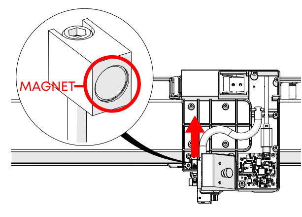
Image 6 : Orientation correcte de l'aimant.
Important : une orientation incorrecte de l'aimant empêchera l'AFP de revenir à sa position de repos.
Test de l'AFP
-
Test the plunger movement.
Press up on the AFP and release it. The plunger should quickly return to its resting position. If it does not, verify the magnet block is seated correctly and not crooked.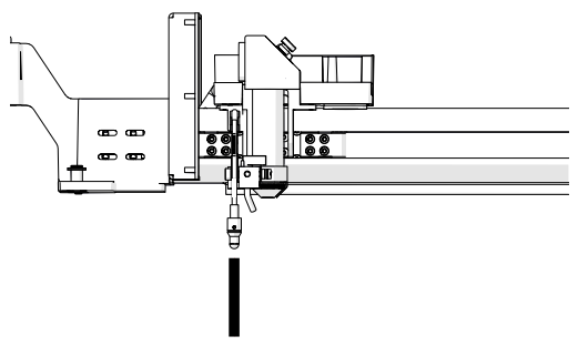
Image 7 : Test du mouvement du piston AFP.
-
Power on the engraver.
Reconnect the power cable and turn the engraver back on. -
Open the Settings menu.
On the display panel, press the gear icon in the upper-right corner to open the Settings menu.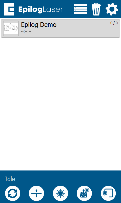
Image 8 : Accès au menu Paramètres.
-
Access Focus Settings.
Press“Focus” on the display to access the Focus Menu.
Image 9 : Accès aux paramètres de mise au point.
-
Run the AFP sensor test.
Turn Calibration Mode ON by pressing the “plus” symbol. Then select Table. Press up on the AFP and confirm that the “Plunger” indicator box on the right side of the screen activates. This ensures the sensor is functioning correctly.
Image 10 : Menu Focus Commands affichant la sélection Table.
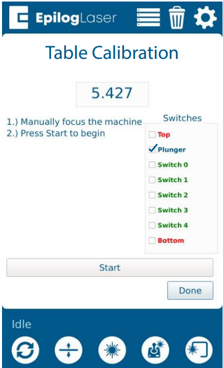
Image 11 : Appuyer sur l'AFP pour tester l'activation du capteur.
Assemblage final
-
Reinstall the carriage cover.
Place the carriage cover back onto the assembly.
Image 11 : Réinstallation du couvercle du chariot.
-
Secure the cover.
Install and tighten the nine (9) Torx screws that hold the carriage cover in place.
Image 12 : Fixation du couvercle du chariot à l'aide de vis Torx.