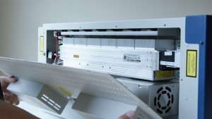
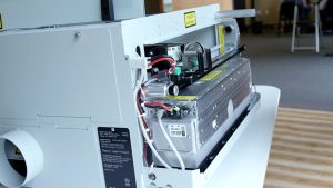
Geschatte tijd: 20–30 minuten • Vaardigheidsniveau: gemiddeld
Deze procedure helpt je bij het verwijderen en installeren van de laserunit in je Epilog Zing . Als je deze stappen volgt, zorg je ervoor dat je graveersysteem goed is uitgelijnd, stevig is gemonteerd en optimaal presteert.
Laserverwijdering
-
Power down and disconnect the machine.
Turn off the engraver and unplug it from the power source. -
Remove the left-hand side panel.
Remove the four Phillips screws securing the side panel: three on the side and one on the rear.
Afbeelding 1: Schroeven van het zijpaneel (zijaanzicht).

Afbeelding 2: Schroef zijpaneel (achterkant).
-
Disconnect the laser power harness.
Located above and behind the laser assembly, press the lock and pull the connector toward you to disconnect.
Afbeelding 3: Laserkrachtkabelboom.
-
Disconnect the data cable.
Press the locking tab and remove the data cable from the laser assembly.
Afbeelding 4: Laserdatakabel.
-
Remove the laser mounting plates.
The laser is held by two green mounting plates inside the engraving area on the left side. Loosen the four outer screws (Picture 5a) but do not remove the inner guide screw (Picture 5b). The screws will pop slightly but remain attached to the mount.
Afbeelding 5: Buitenste schroeven op montageplaten.

Afbeelding 6: Binnenste geleidingsschroef.
-
Remove the laser assembly.
Lift slightly and align the guide pin with the slot in the chassis. Slide the laser assembly toward the front and remove it from the machine.
Afbeelding 7: Waar de laserbevestigingsplaat zit.
Laserinstallatie
-
Install the laser assembly.
Align the guide pins with the chassis holes, push the assembly against the side, and slide it forward until seated. -
Install the mounting plates.
Loosely install the four screws on each mounting plate. Once all screws are in place, tighten all eight screws securely. -
Sluit de datakabel weer aan.

Afbeelding 8: Datakabel weer aangesloten.
-
Sluit de stroomkabel weer aan.

Afbeelding 9: Stroomkabel weer aangesloten.
-
Perform laser alignment.
After installation, perform a full laser alignment as described in the Epilog Technical Note: Zing Laser Alignment.