所要時間:30~45分 •難易度:中級
この手順書は、Fusion Pro 32 および 48 レーザーシステムにおけるテーブル(Z軸)ベルトの取り外しと取り付けをガイドします。正確な彫刻を実現するため、正しいベルトの経路、適切な張力、滑らかなZ軸動作を確保するには、以下の手順に従ってください。
Z軸ベルトの取り外し
-
Power down and disconnect the engraver.
Turn off the engraver and unplug it from the power source. -
Remove access panels.
Remove the front and right side panels of the engraver.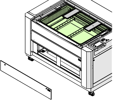
画像1:前面パネルを取り外した状態。
-
Mark the motor location.
Use a pencil to mark the leading edge of the Z-Axis motor body on the chassis. This will help set proper belt tension during reinstallation.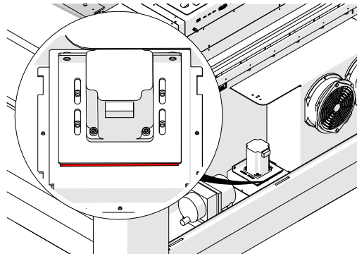
画像2:Z軸モーターの位置をマークする。
-
Z軸モーターハーネスを外してください。
-
Release belt tension.
Loosen, but do not remove, the two 7/64” Allen screws on the tensioner.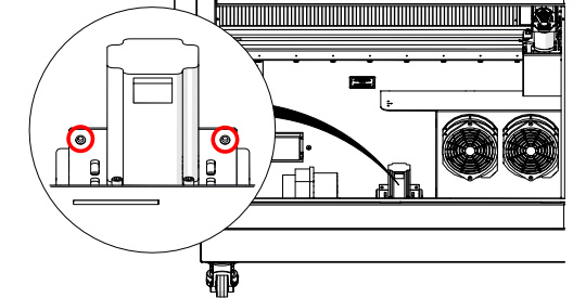
画像3:テンショナーのネジを緩める。
-
Remove motor mounting screws.
Loosen and remove the four 7/64” Allen screws securing the Z-Axis motor to the chassis.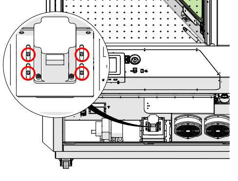
画像4:モーター取付ネジを外す。
-
Z軸モーターを取り外してください。
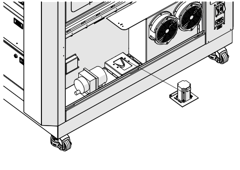
画像5:Z軸モーターを取り外した状態。
-
Remove the Z-Axis belt.
Press the belt flat against the bottom of the chassis and slip it underneath each lead screw pulley.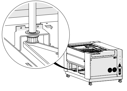
画像6:Z軸ベルトを外した状態。
Z軸ベルトの取り付け
-
Place the Z-Axis belt in the chassis.
Press the belt flat against the bottom of the chassis and slip it underneath each lead screw pulley. Ensure the toothed side wraps around the pulleys correctly.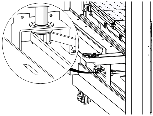
画像7:Z軸ベルトの正しいルーティング。
-
Reinstall the Z-Axis motor.
Position the motor so the pulley fits inside the belt, and loosely install the four 7/64” Allen screws.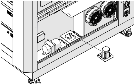
画像8:Z軸モーターの取り付け完了。
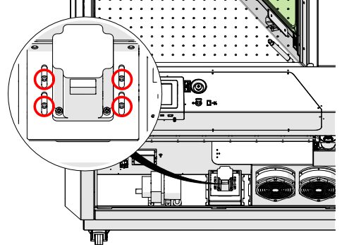
画像9:モーター取付ネジ。
-
Route belts on all lead screws.
Repeat for all four lead screw assemblies, ensuring proper routing.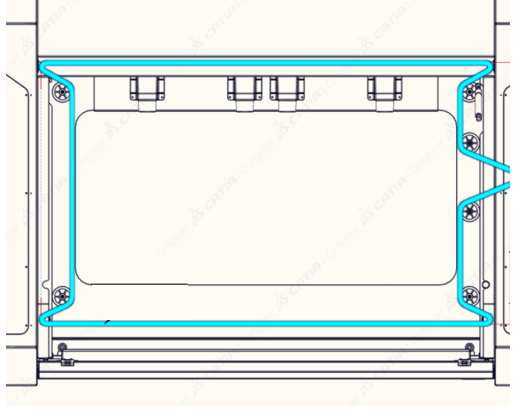
画像9:全リードスクリューにおけるベルトの経路設定
-
Inspect belt placement.
Ensure the belt remains seated on all pulleys. Reposition if needed.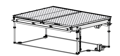
画像11:ベルトの配置を確認する。
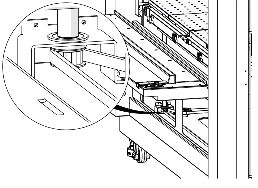
画像12:プーリーの点検
-
Tension the belt.
Tighten the two 7/64” Allen screws on the tensioner until the motor aligns with the pencil mark made earlier.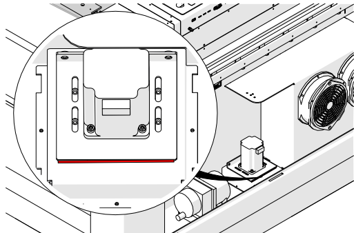
画像13:ベルトの張りを調整しました。
-
Secure the motor.
Tighten the four motor mounting screws.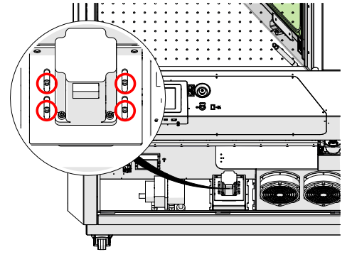
画像14:モーター固定済み。
-
Z軸モーターハーネスを再接続してください。
-
Reinstall all access panels.
Replace the front and right panels of the engraver.
画像16:アクセスパネルの再設置。