
This procedure details steps to replace the belt that carries the laser head. These belts may get worn out and must be replaced for optimal performance from your machine. Always ensure proper safety precautions are taken when servicing hardware components.
Procedure Steps
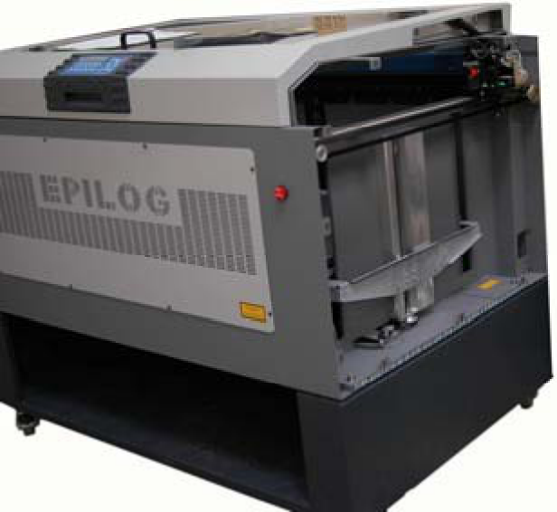
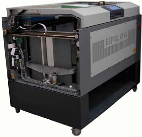
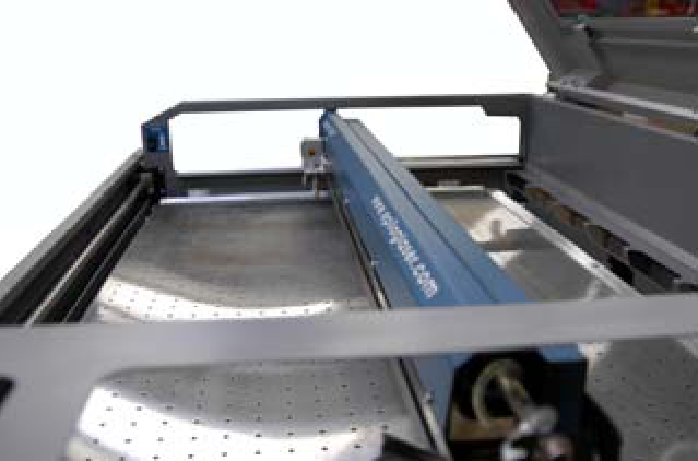
Center the I-beam
Bring the I-beam to the center of the engraving table.
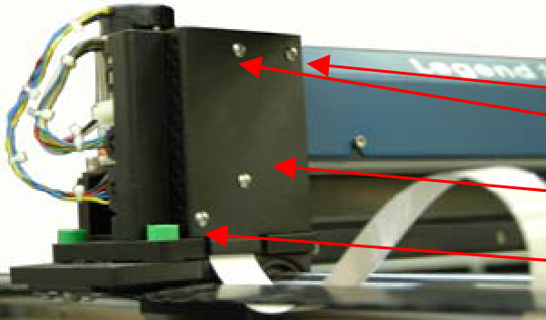
Remove amplifier cover
Take off the amplifier cover found on the left side of the I-Beam by unscrewing the four screws.
Remove the blue I-beam cover
Remove the blue cover on the I-beam. This cover is attached to the I-beam by five hexagonal screws in the front and five Philips head screws in the back. Use the 7/64 Allen wrench to take out the front screws. For the back of the I-beam, only remove the Philips head screws directly attached to the I-beam; smaller screws in the center and left side can be left alone.
Remove the laser head
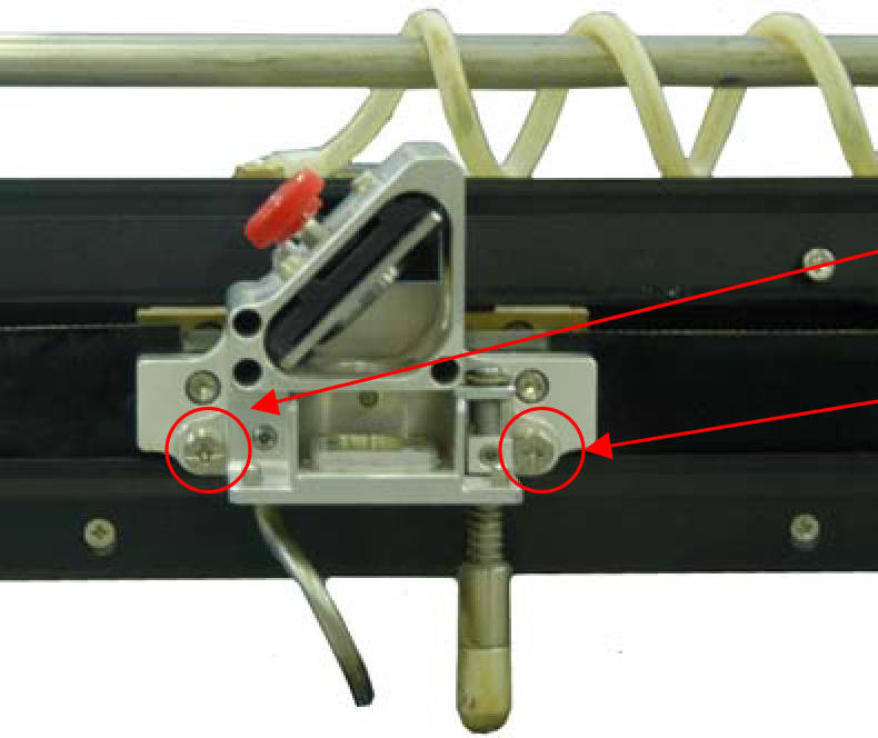
Remove the laser head by unscrewing the two screws securing it.
Loosen belt spindle screws
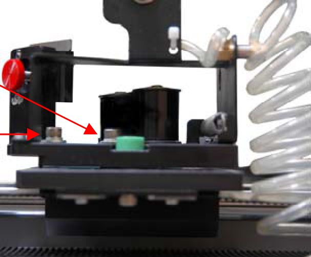
Slacken the belt by loosening the two screws holding the belt spindles.
Slacken and lock spindle position
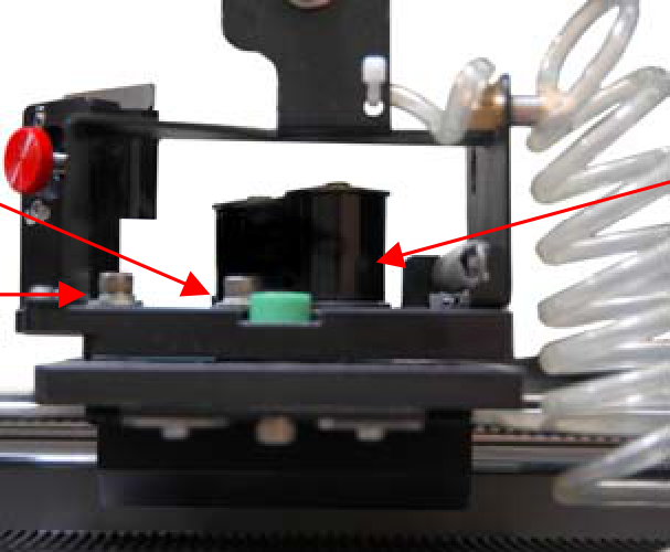
With your thumb, press hard on the spindle farthest to the right until the belt slackens. While still pressing on the spindle, tighten the two screws that were loosened in the previous step to hold the spindle in place.
Loosen belt clamp screws
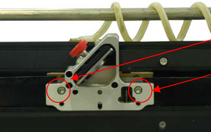
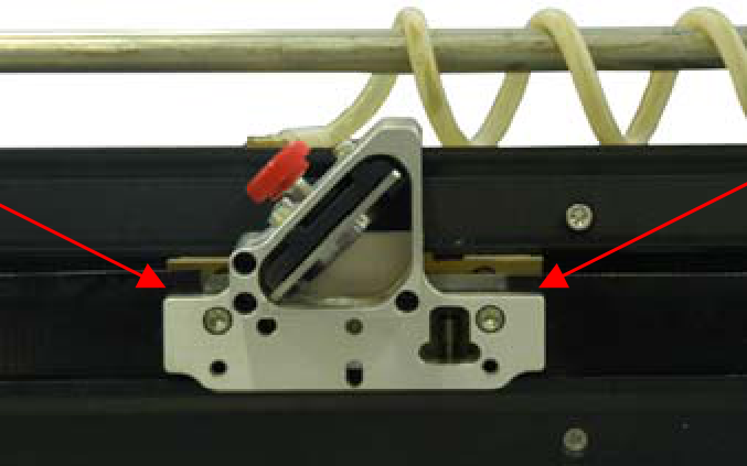
Locate the ends of the belt connected to the laser head. The belt is held by a clamp with two hexagonal screws. Using a 7/64 Allen wrench, loosen these screws.
Remove the old belt
Pull the belt ends up and out of the clamp. Slowly pull on one end of the belt until it comes out entirely.
Orient new belt
Take a new belt and ensure the grooves face toward the inside of the machine.
Route new belt through I-beam
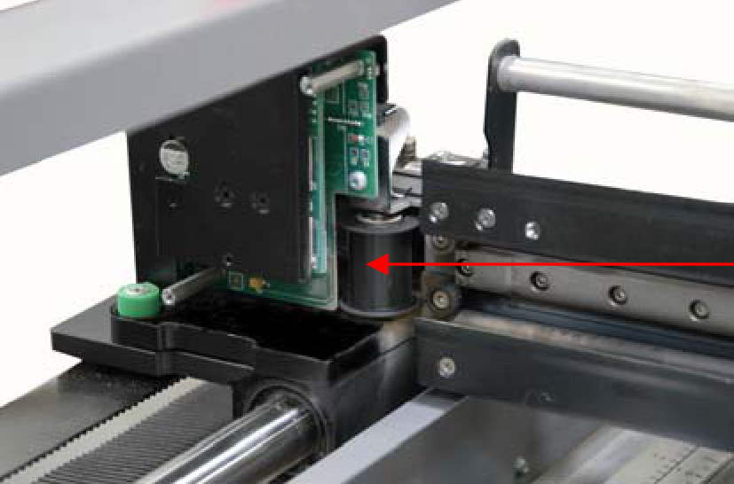
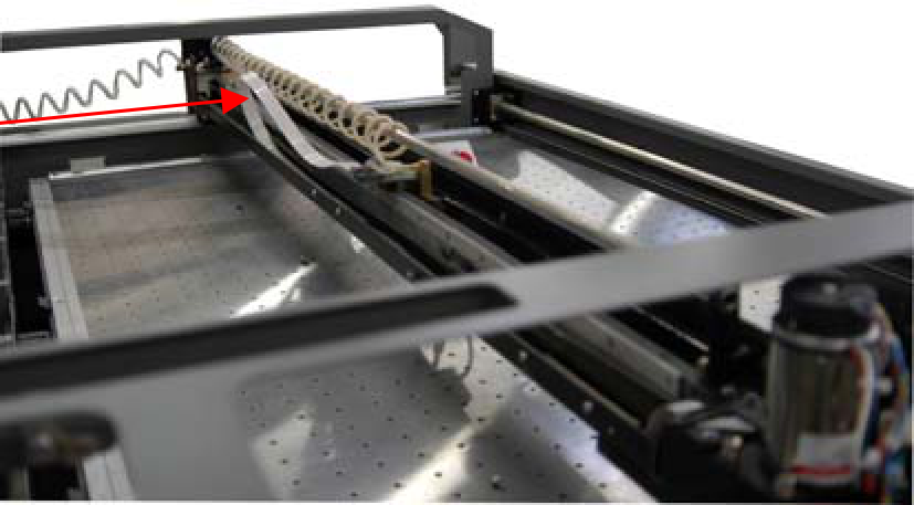
Put the left end of the belt through the left side of the I-beam between the black spindle and the control board. Push the belt through the motor covering, ensuring it loops around the silver spindle. Pull the belt close to the I-beam on the inside of the white-red ribbon cord. Loop the belt around both of the black spindles and back toward the laser head. Insert each end into its respective end of the clamp and tighten the hexagonal screws.
Tension the belt
Loosen the screws holding the right side pulley to allow the belt to tighten. When the spindle returns to its furthest back position, tighten the screws.
Reinstall I-beam cover
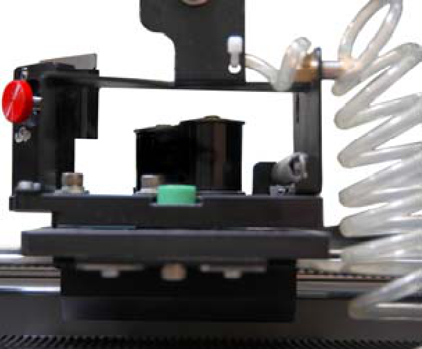
Put the I-beam cover back on. Raise the front edge slightly while screwing it in so the hexagonal screws do not hinder movement. Slide the laser head back and forth to test clearance; if it hits a screw, loosen the cover, lift slightly, and retighten.
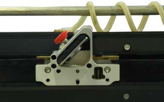
Reinstall amplifier cover
Replace the amplifier cover using the four screws.
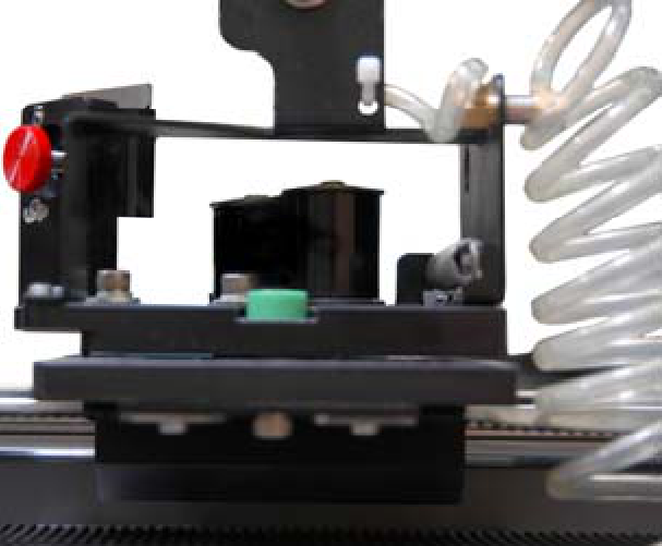
Reinstall side panels
Reattach both side panels to complete the installation.