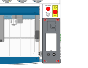
This guide provides step-by-step technical instructions for replacing the control board, SD card, coin battery, and backplane on your Ascent laser system.
安全第一:内部の電子機器に触れたり、接続を解除したりする前に、レーザーシステムの電源が完全に切れていること、および主電源コードが壁のコンセントから抜かれていることを確認してください。露出している電源装置の部品には絶対に触れないでください。
ESD Precaution: Always wear an anti-static wrist strap grounded to the machine’s bare metal chassis before handling the control board, backplane, or other sensitive electronic components to prevent electrostatic discharge damage.
Section 1: Control Board Removal
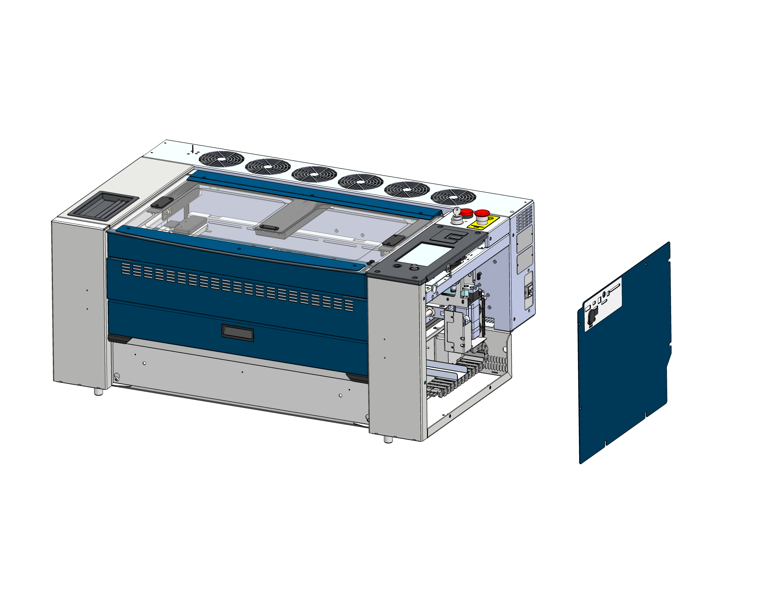
サイドパネルを取り外す
Locate and remove the right side panel of the laser chassis to gain access to the electronics.
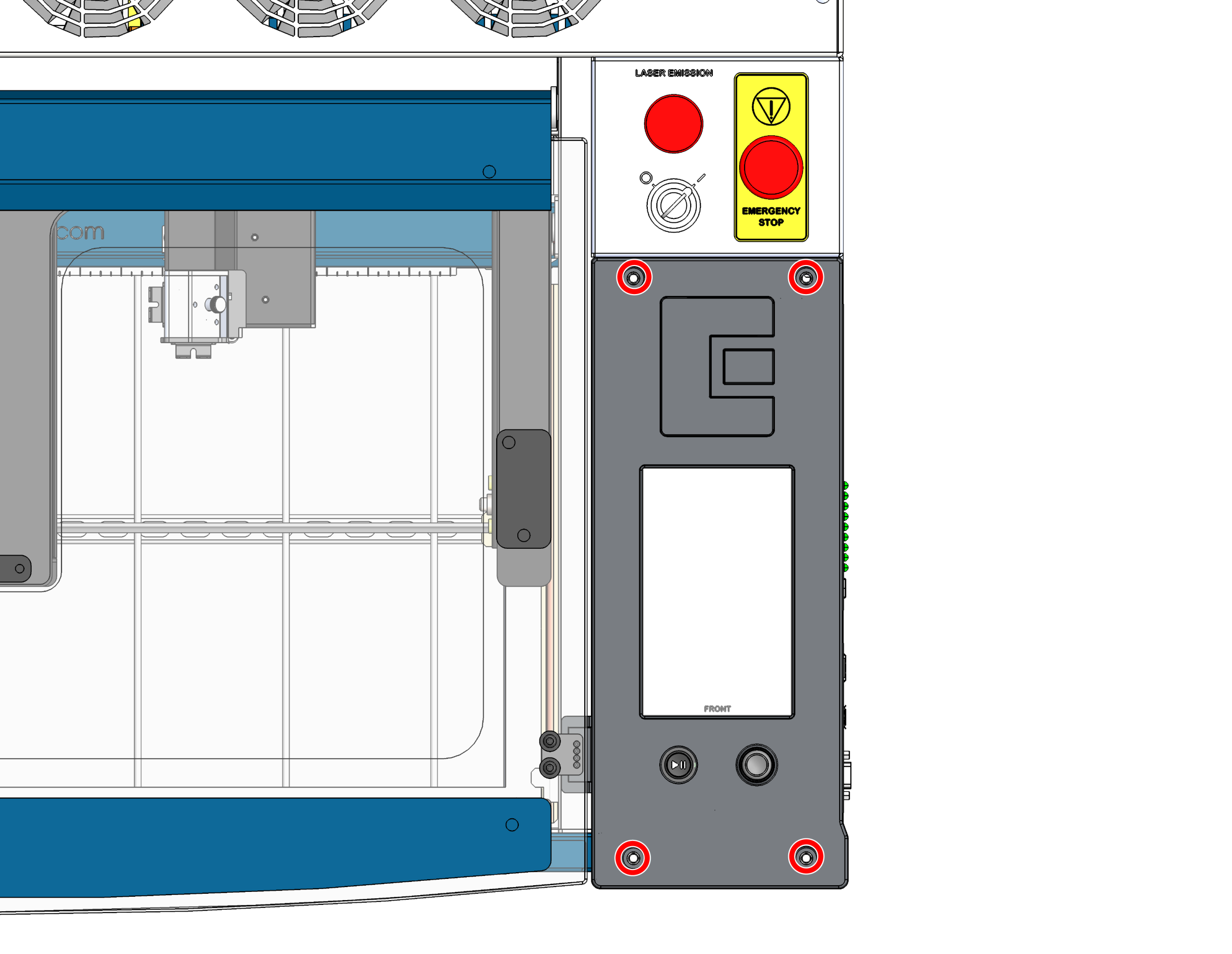
制御基板のネジを取り外す
コントロールボードをシャーシに固定している4本のネジを取り外してください。
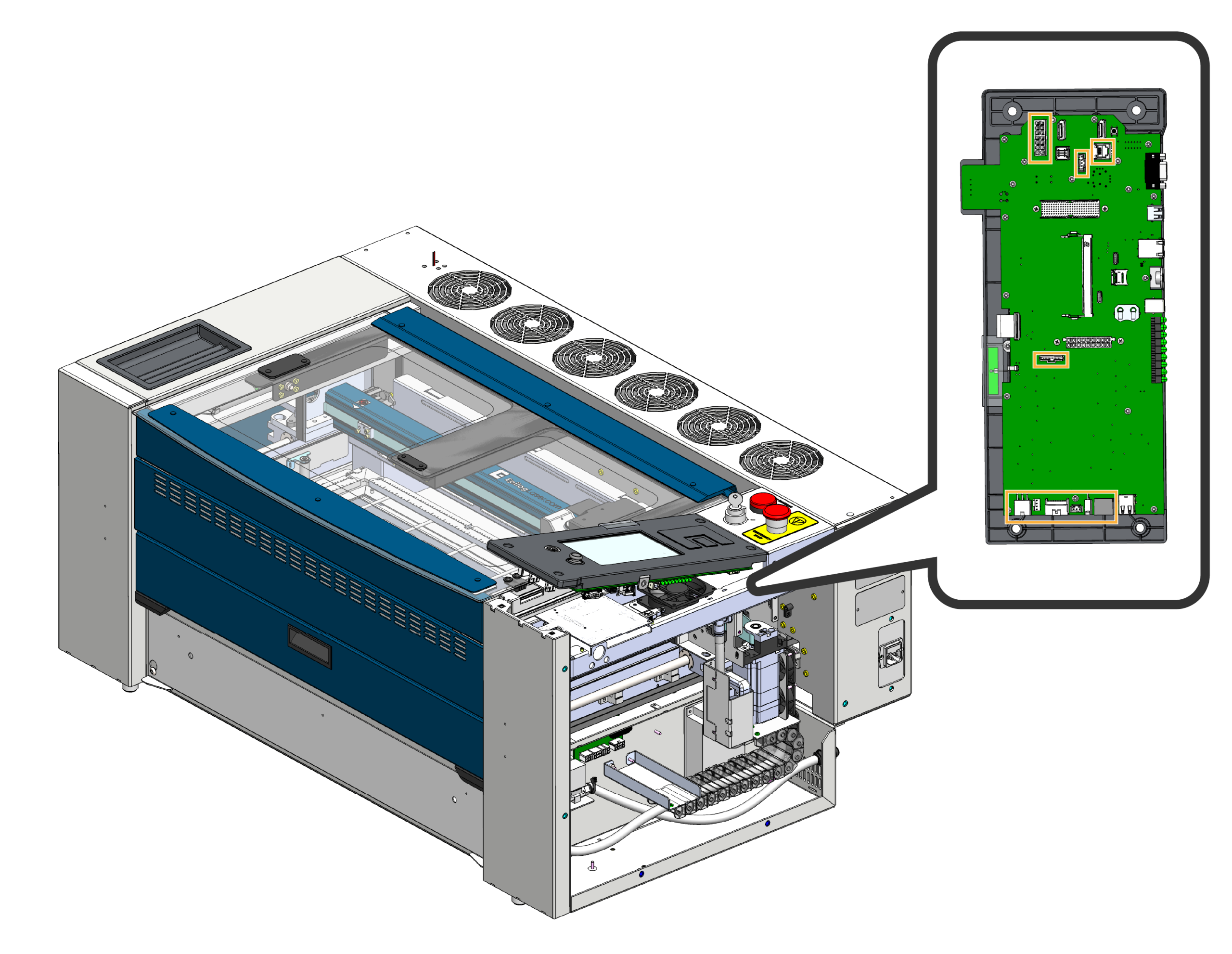
ハーネスの取り外し
制御基板の前部を慎重に上方に傾け、制御基板に接続されているワイヤーハーネスを取り外してください。
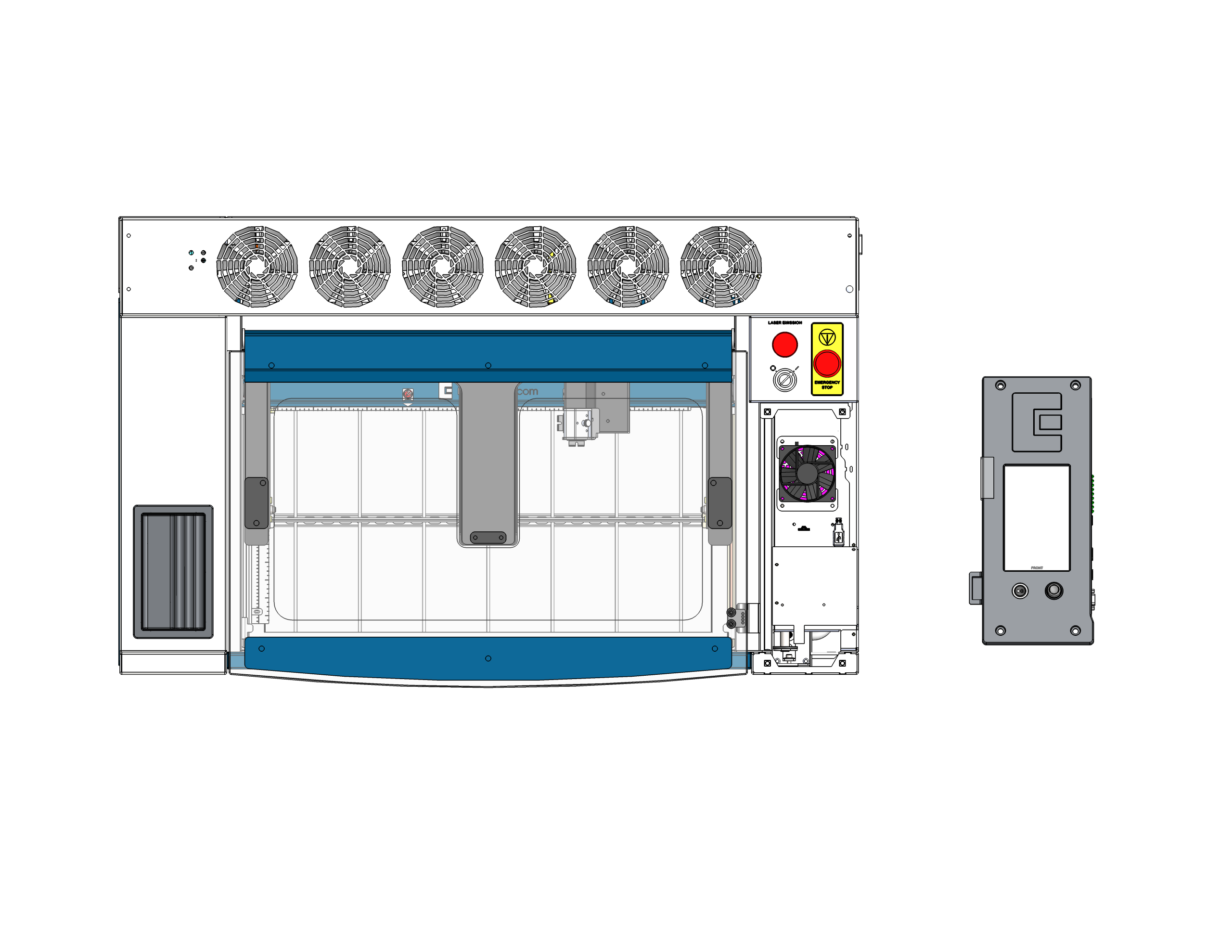
制御基板を取り外す
コントロールボードを本体から取り外し、完全に取り出してください。静電気の出ない安全な場所に、表面を下にして置いてください。重要:ボードの裏側で作業を行う際、ジョイスティックが押しつぶされたり破損したりしないよう、ジョイスティックが作業台の端からはみ出しているか、あるいは柔らかい素材の上に置かれていることを確認してください。
Section 2: SD Card & Coin Battery Replacement
コントロールボードを画面を下にして安定させておけば、ボード上に設置されているSDカードやコイン型電池に簡単にアクセスして交換することができます。
SDカードの交換
Locate the SD card slot on the control board. Gently press the metal holder towards the center of the control board to open the door. Remove the old SD card and insert the new one.
コイン型電池の交換
制御基板上のコイン型電池の収納部を見つけます。古い電池を固定クリップから慎重に引き抜きます。新しい電池を、プラス(+)側が上を向くように挿入します。
Section 3: Backplane Replacement
バックプレーンのネジを取り外す
Locate the backplane mounted to the left inside of the chassis. First, remove the 4 screws securing the backplane to the chassis to give yourself some slack.
ケーブルを取り外す
With the board unscrewed, carefully disconnect all wiring harnesses and cables plugged into it. Once everything is disconnected, lift the old backplane out of the machine.
Install New Backplane
Position the new backplane in the chassis. Systematically reconnect all the cables you removed in Step 8 first. Once all cables are securely plugged in, align the board and reinstall the 4 screws to mount it to the chassis.
Section 4: Reassembly & Installation
リコネクト制御基板のハーネス
コントロールボード(新しいSDカードとバッテリーを取り付けた状態)を、取り付け場所に慎重に近づけ、ワイヤーハーネスをボードに再接続してください。
シート制御基板
コントロールボードをネジ穴の真上に位置合わせします。ボードが新しく取り付けられたバックプレーンにしっかりと固定されるよう、均等にしっかりと押し込んでください。
セキュア制御ボード
4本のネジを再度取り付け、しっかりと締め付けて、完全に所定の位置に収まった制御基板をシャーシに固定してください。
サイドパネルを交換する
本機の右側パネルを再度取り付け、しっかりと固定してください。
最終確認
本体を壁のコンセントに再び差し込み、電源を入れてください。タッチスクリーンが正常に起動し、本体が正常に初期化されることを確認してください。これにより、新しい基板、SDカード、バッテリー、およびバックプレーンがすべて正しく通信していることが示されます。