8000 - Mini/Helix Z-Axis Table Motor Install
How do I replace the Z-motor in my Epilog Mini or Helix?
Machine Type:Epilog Mini 18/24, Helix
Tools Needed:
- Philips head screw driver
- 5/16 Nut Driver
- 3/32 Hex wrench
- Wire Cutters
- Sharpie Marker
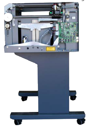
This procedure details steps to replacing the Z-motor. The Z-motor drives the Z-belt, which controls the engraving table up and down. Before starting on this procedure, raise the table to the top and then disconnect the power cord.
Remove the right side panel
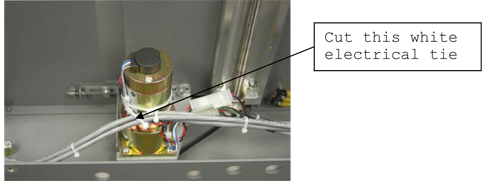
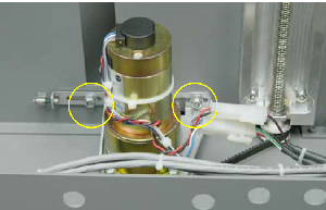
Cut the white electrical tie around the motor and the grey set of wires.
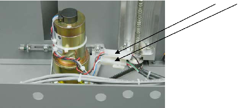
Disconnect the two electrical connectors.
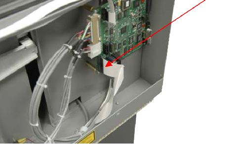
Disconnect the white ribbon cable connected to the control board.
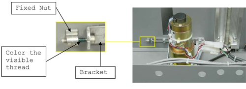
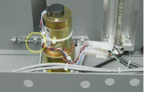
A 3/32 hexagonal screw controls the tightness of the belt. The belt needs to be at certain tightness in order for the motor to work properly. Therefore, before removing the bracket, obtain a Sharpie marker. Color the visible thread between the bracket and the fixed nut. Be sure to color the edge of the thread and the fixed nut.
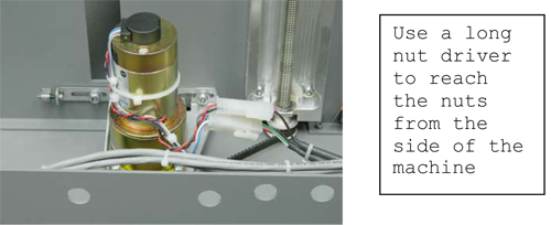
With a long 5/16 nut driver, unscrew the two nuts on the motor bracket.
Unscrew the 3/32 hexagonal screw.
Remove Z-motor and bracket.
Obtain a new motor. The new motor will come with a bracket already installed.
Getting the Z-belt around the pulley is a little tricky.
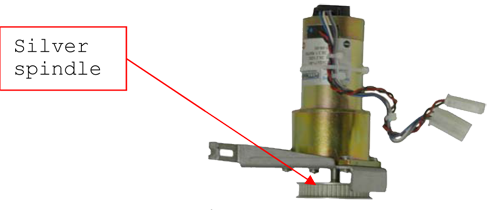
a. Pull the silver pulley down a quarter of an inch (6.35mm).
b. Put the new motor and bracket into the machine at an angle.
c. Slip the belt around the pulley. Make sure the belt is squarely on the pulley.Position the motor bracket on the fixed screws.
Place the nuts on the fixed screws. Do not tighten the nuts.
Tighten the hexagonal tensioning screw until the edge of the black mark is at the edge of the fixed nut. Getting the precise placement of the black mark is very important. The mark should be in the exact same spot as it was before the screw was taken out.
Tighten the two nuts holding the motor bracket.
Loosen the left nut a quarter of a turn.
Reconnect the motor leads.
Reconnect the white ribbon cable to the control board.
Replace the right side panel.