The camera calibration ensures that the IRIS camera system offers optimum accuracy when displaying artwork on material and when completing print-to-cut applications. The camera calibration should not be completed regularly. Instead, the camera calibration should only be completed if any of the following behaviors are observed:
- Camera feed appears completely black.
- Camera feed displays a black semi-circle overlay.
- Camera feed appears rotated 90-180 degrees.
- Camera feed of the art placement location does not coincide with the location of the engraving and or cuts
on material.
Additionally, a camera calibration may be needed if any of the following components have been replaced or
certain engraver settings have been changed:
- Overhead or carriage camera
- Laser Focus
- Home position
Many location-based camera errors are caused by focus or positioning issues. Before completing a camera
calibration to resolve a location-based camera issue, ensure that the engraver is properly focused and the accuracy of the XY home position.
All focus calibrations must be completed before a camera calibration to ensure accurate results
Note: All focus procedures must be completed prior to the camera calibration procedure to ensure an accurate calibration.
Overhead Camera Calibration (Edge)
-
Turn on the engraver, and let it complete the startup process.
-
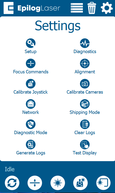
On the display, press the gear icon to enter the Settings menu.

-
Press and hold the word “Settings” that appears at the touch of the touchpad to gain access to the Advanced Settings menu.

-
Press Calibrate Cameras.
-
Place a piece or pieces of anodized aluminum that match the table size of the engraver in the table of the engraver:
- Edge 12 – one (1) 24” x 12” or 610 x 305mm piece
- Edge 24 – two (2) 24” x 12” or 610 x 305mm pieces
- Edge 36 – three (3) 24” x 12” or 610 x 305mm pieces
-
Close the top door of the engraver.
-
Press OK to begin the carriage camera calibration and the engraver will move the table to the appropriate focal height for calibration.
-
The engraver will mark the anodized aluminum with a pattern that the overhead camera analyzes for
calibration. -
The engraver will use the overhead cameras to read the unique markings and analyze their position on the
aluminum Allow 15-30 minutes for this portion of the calibration: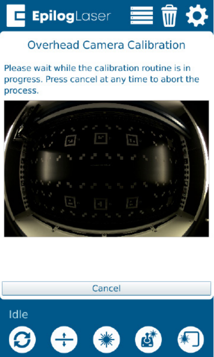
-
Once the calibration has finished, a “Reprojection Error” will appear. The value that is shown corresponds
to the accuracy of the camera calibration. -
If the Reprojection Error is above 2.0, the camera calibration will fail. A value of 1.0 or lower represents an acceptable camera calibration; however, a value of 0.75 or lower is desired.
Camera Calibration (Fusion Pro 24 & 36)
The camera calibration ensures that the IRIS camera system offers optimum accuracy when displaying artwork on material and when completing print-to-cut applications. The camera calibration should not be completed regularly. Instead, the camera calibration should only be completed if any of the following behaviors are observed:
- Camera feed appears completely black.
- Camera feed displays a black semi-circle overlay.
- Camera feed appears rotated 90-180 degrees.
- Camera feed of the art placement location does not coincide with the location of the engraving and or cuts
on material.
Additionally, a camera calibration may be needed if any of the following components have been replaced or
certain engraver settings have been changed:
- Overhead or carriage camera
- Laser Focus
- Home position
Many location-based camera errors are caused by focus or positioning issues. Before completing a camera
calibration to resolve a location-based camera issue, ensure that the engraver is properly focused and the accuracy of the XY home position.
All focus calibrations must be completed before a camera calibration to ensure accurate results
Note: It is advised to remove the calibration mat from the cardboard tube it is shipped in and laying it checkerboard side down on a flat surface at least an hour before completing the camera calibration. This ensures that the calibration mat will lay flat in the engraver and will result in a more accurate camera calibration.
This procedure should not be completed with the vector grid or slat assembly in the engraver. Ensure that the raster table is installed while completing this procedure.
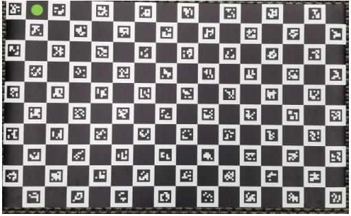
Camera Calibration Mat:
Carriage Camera Calibration (Pro)
-
Turn on the engraver, and let it complete the startup process.
-
On the display, press the gear icon to enter the Settings menu.

-
Press and hold the word “Settings” on the touchpad to gain access to the Advanced Settings menu.

-
Press Calibrate Cameras.

-
Place an 8” x 5” (200mm x 125mm) piece of anodized aluminum in the top left corner of the table.
-
Close the top door of the engraver.
-
Press OK to begin the carriage camera calibration and the engraver will move the table to the appropriate focal height for calibration.
-
The engraver will mark the anodized aluminum with a pattern that the carriage camera analyzes for calibration. Once the job is complete, a success message should appear.
-
Follow the on-screen prompts to continue to the overhead camera calibration.
Overhead Camera Calibration (Pro)
-
Remove the anodized aluminum from the engraver and place the calibration mat on the engraving table.
-
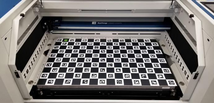
Ensure that the green circle is positioned in the upper-left corner of the engraving table. Additionally, Ensure that the calibration mat lays as flat as possible on the raster table to achieve the most accurate camera calibration possible:
-
Once the calibration mat is placed on the table, close the top and front door of the engraver.
-
Press OK to begin the overhead camera calibration.
-
The engraver will use the overhead cameras to read the unique markings and analyze their position on the mat. Allow 15-30 minutes for this portion of the calibration.
-
Once the calibration has finished, a “Reprojection Error” will appear. The value that is shown corresponds to the accuracy of the camera calibration.
-
If the Reprojection Error is above 2.0, the camera calibration will fail. A value of 1.0 or lower represents an acceptable camera calibration; however, a value of 0.75 or lower is desired.
