16000 - 17000 X-Axis Belt Tensioning Guide
How do I tension the X-Axis belt on my Fusion Edge, Maker, or Pro?
Overview
This document and video provide instructions on utilizing the X-Axis belt tensioning tool. The tool assesses the belt's tightness, allowing us to adjust the idler pulley on the machine's left side accordingly. Incorrect belt tension can lead to drive errors, quality problems, and other unexpected issues.
Identifing X-Axis Rail Version
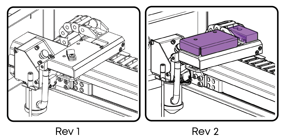
Before beginning, identify which version of the X-Axis rail is in your machine. If your lens carriage has the covers highlighted below, follow the Rev 2 procedure. If not, follow the Rev 1 procedure
Required Tools
- 7/64" Hex Driver
- 5/32" Hex Wrench
- CS1280 Belt Tensioner
Rev 1 Procedure
-
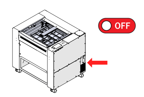
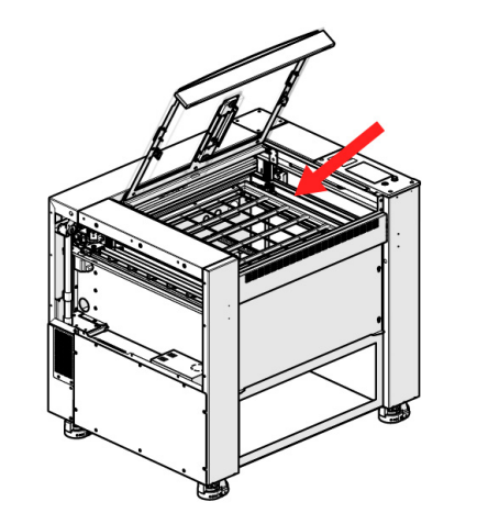
Power OFF machine.
-
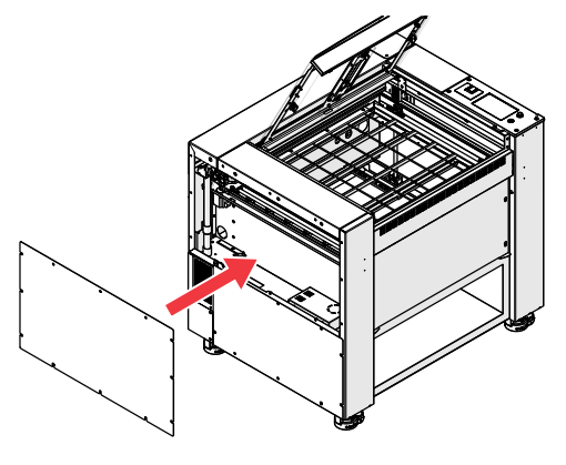
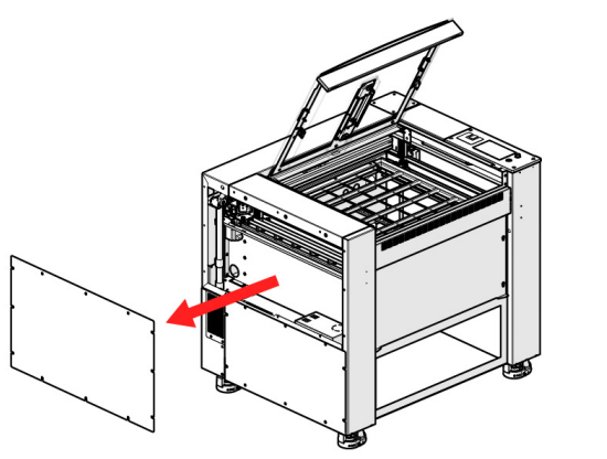
Remove the left side panel.
-
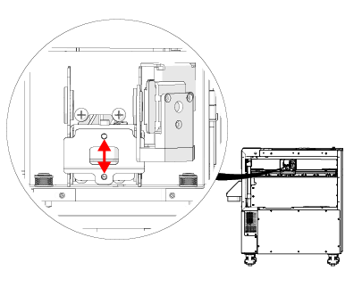
Manually move the carriage to the right, and down about halfway.
-
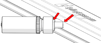
Insert the tip of the tensioner tool into the center of the X-axis belt. Notches must align with rail.
Note: The notches on the tensioner tool must align with the cutout on the X-axis rail. This is necessary for the tool to provide an accurate reading.
-
When the tool is seated flush against the X-axis rail, the O-ring on the rear shaft will indicate the belt tension.
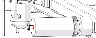
Warning: Do NOT attempt to adjust the belt tension tool. These are calibrated at the factory.
Reading Belt Tensioner
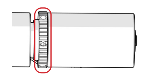
- If the O-ring is flush with the body of the tensioner tool, the belt is properly tensioned.
- If the O-ring is not visible, the belt tension is too low.
- If there is a gap between the O-ring and the body of the tool, the belt tension is too high.

-
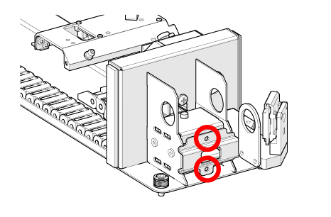
To adjust the tension of the X-Axis belt, begin by loosening eight (8) 7/64” hex screws on the X-Axis idler assembly.

BACK

FRONT
-
Evenly turn the two (2) 7/64” hex screws on the end of the X-Axis idler assembly.
Note: Tightening these two screws adds tension to the belt. Loosening, will remove tension.
-
Repeat steps 4 and 5, continually checking the belt tension after adjusting the tensioner screws.
-
Once the O-ring is flush with the body of the tool, continue with the “Belt Tracking” section of this document.
Belt Tracking
-
Open your preferred illustrating program and create a black, raster box that is roughly two (2) inches smaller than the bed and four (4) inches tall.
-
Set the speed to 100% and the power to 0%.
-
Send the job to the engraver, open the top door, and start the job.
-
The belt should stay in the middle of the idler pulley as the carriage head moves left to right.
-
If the x-axis belt is riding against the idler pulley flange, make equal but opposite adjustments to the two (2) 7/64” tensioner screws.
If the X-Axis belt is too high
- Tighten the top screw 1/4 turn
- Loosen the bottom screw 1/4 turn
If the X-Axis belt is too low
- Loosen the top screw 1/4 turn
- Tighten the bottom screw 1/4 turn
-
Once the belt is tracking properly, confirm that the belt tension is still set properly.
-
Once the belt tracking and tension are properly set, you can tighten down the eight (8) 7/64” hex screws to lock the idler pulley in place.
BACK
FRONT
Rev 2 Procedure
-
Power OFF machine.
-
Remove the left side panel.
-
Manually move the carriage to the right, and down about halfway.
-
Insert the tip of the tensioner tool into the center of the X-Axis belt. Notches must align with rail.
Note: The notches on the tensioner tool must align with the cutout on the X-Axis rail. This is necessary for the tool to provide an accurate reading.
-
When the tool is seated flush against the X-Axis rail, the O-ring on the rear shaft will indicate the belt tension.
Warning: Do NOT attempt to adjust the belt tension tool. These are calibrated at the factory.
Reading Belt Tensioner
- If the O-ring is flush with the body of the tensioner tool, the belt is properly tensioned.
- If the O-ring is not visible, the belt tension is too low.
- If there is a gap between the O-ring and the body of the tool, the belt tension is too high.
-
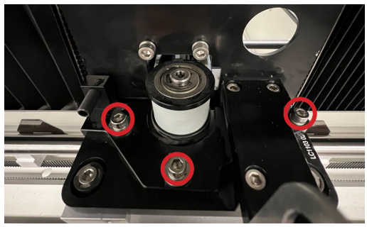
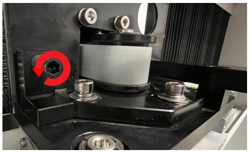
To adjust the belt tension, loosen the three 5/32” hex screws on the tensioner.
-
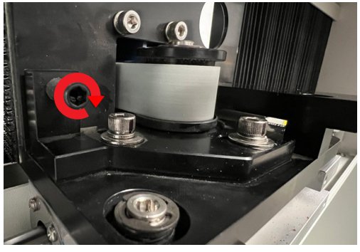
If the tension is low, tighten the 5/32” tensioner adjustment screw.
-
If the tension is high, loosen the 5/32” tensioner adjustment screw.
-
Check the tension.
-
When the tension is set properly, tighten the three (3) 5/32” screws on the tensioner.

-
Replace the side cover.