10000 - Y-Axis Belt Replacement
How do I replace the Y-Axis belt on my Zing machine?
Required Tools
- Phillips Head Screwdriver
- RC0051-C Y-Axis Belt (Zing 16)
- RC0051-D Y-Axis Belt (Zing 24)
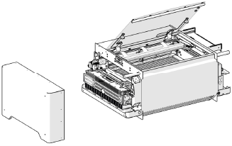
Getting Started
-
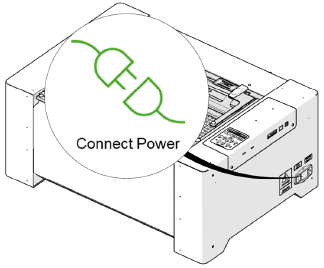
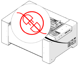
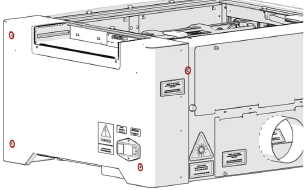
Disconnect power.
-
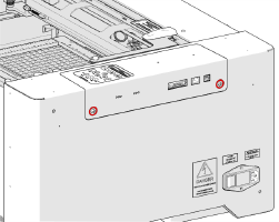
Loosen two (2) captive screws.
-
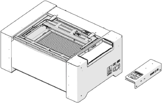
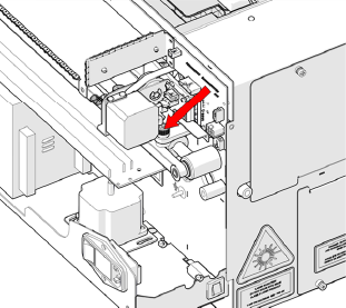
Remove control board.
-
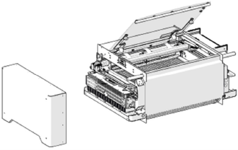
Remove four (4) Phillips head screws.
-
Remove side panel.
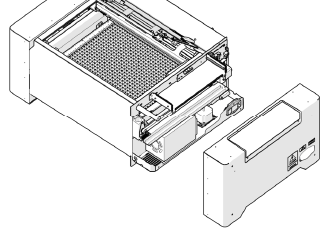
-
Open top door.
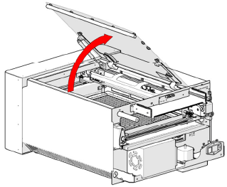
-
Remove four (4) Phillips head screws.
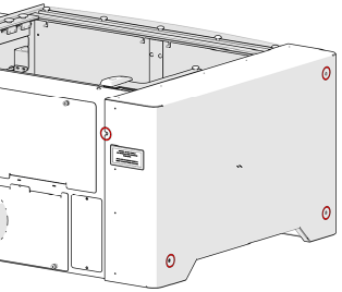
-
Remove side panel.
-
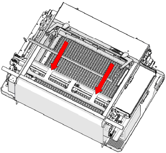
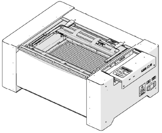
Move X-Axis rail to front of machine.
-
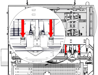
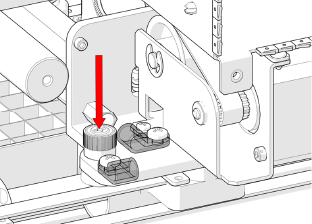
Loosen green captive screw.
-
Move X-Axis rail to back of machine.
-
Loosen green captive screw.
-
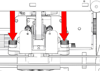
Loosen two (2) green captive screws on left-side of X-Axis rail.
-
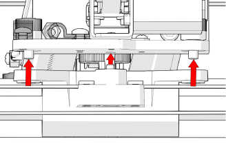
Move X-Axis to front of machine and lift.
-
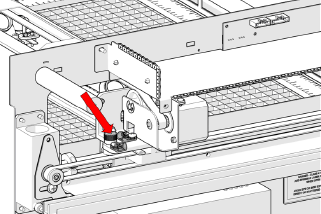
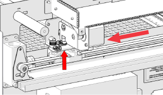
Move bearing block to rear of machine.
-
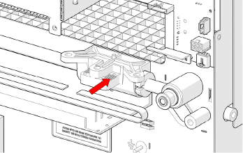
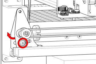
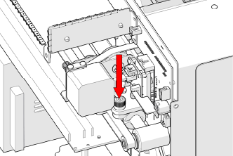
Loosen tensioner screw.
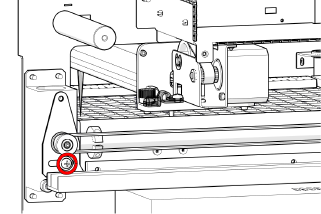
-
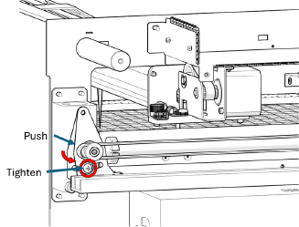
Push and hold tensioner pulley towards rear, then tighten screw.
-
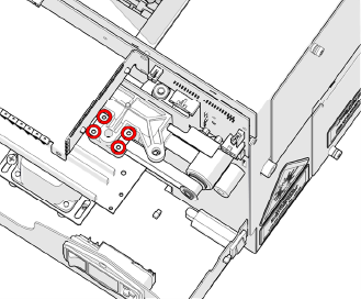
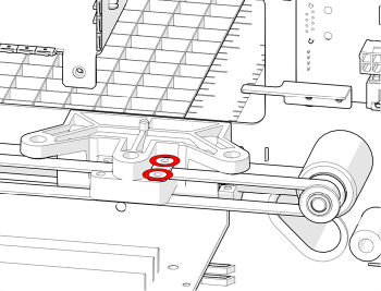
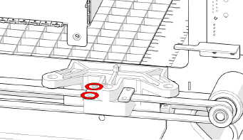
Remove four (4) Phillips head screws on belt clamps.
-
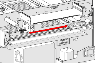
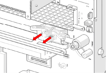
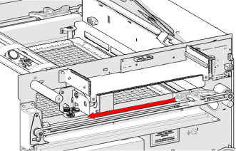
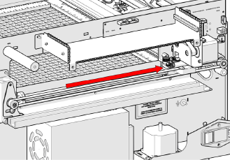
Remove belt.
-
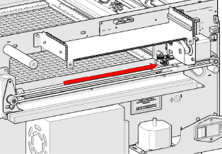
Install replacement belt.
-
Install two (2) Phillips head screws on rear belt clamp.
-
Feed belt around pulley with teeth facing pulley.
-
Feed belt around front pulley.
-
Install two (2) Phillips head screws on front belt clamp.
-
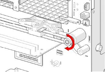
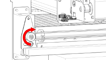
Tension belt by unscrewing and tightening.
Note: If replacing both sides, repeat steps 16 - 25 for left-side.
-
Move bearing block towards front of machine.
-
Align X-Axis rail and bearing block.
-
Tighten green captive screws on left-side of X-Axis rail.
-
Tighten green captive screw.
-
Move X-Axis rail to rear of machine.
-
Tighten green captive screw.
-
Install left-side panel.
-
Install four (4) Phillips head screws.
-
Install right-side panel.
-
Install four (4) Phillips head screws.
-
Insert control board.
-
Tighten two (2) captive screws.
-
Connect power.