
Identifying X-Axis Rail Version
Before you begin, determine which version of the X-Axis rail is installed in your machine. Check the right side of the X-Axis rail: if there is no cutout, you have Revision 1; if there is a cutout, you have Revision 2. Follow the corresponding procedure based on this identification.
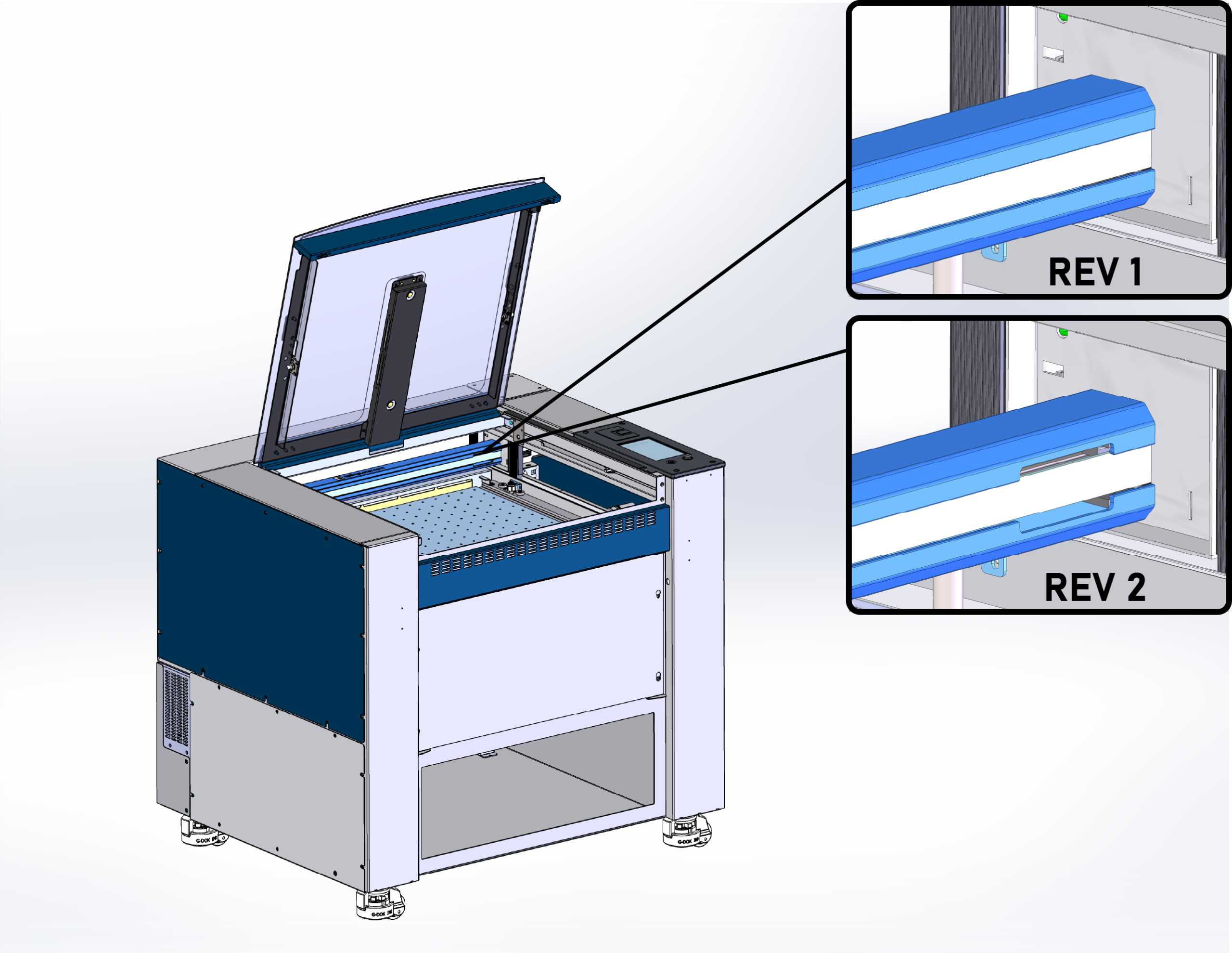
Rev 1 Procedure
-
Power OFF machine.

-
Remove the left side panel.

-
Manually move the carriage to the right, and down about halfway.

-
Insert the tip of the tensioner tool into the center of the X-axis belt. Notches must align with rail.
Note: The notches on the tensioner tool must align with the cutout on the X-axis rail. This is necessary for the tool to provide an accurate reading.
-
When the tool is seated flush against the X-axis rail, the O-ring on the rear shaft will indicate the belt tension.

WARNING: Do NOT attempt to adjust the belt tension tool. These are calibrated at the factory.

Reading Belt Tensioner
- If the O-ring is flush with the body of the tensioner tool, the belt is properly tensioned.
- If the O-ring is not visible, the belt tension is too low.
- If there is a gap between the O-ring and the body of the tool, the belt tension is too high.

-
To adjust the tension of the X-Axis belt, begin by loosening eight (8) 7/64” hex screws on the X-Axis idler assembly.

BACK

FRONT
-
Evenly turn the two (2) 7/64” hex screws on the end of the X-Axis idler assembly.
Note: Tightening these two screws adds tension to the belt. Loosening, will remove tension.
-
Repeat steps 4 and 5, continually checking the belt tension after adjusting the tensioner screws.
-
Once the O-ring is flush with the body of the tool, continue with the “Belt Tracking” section of this document.
Belt Tracking
-
Open your preferred illustrating program and create a black, raster box that is roughly two (2) inches smaller than the bed and four (4) inches tall.
-
Set the speed to 100% and the power to 0%.
-
Send the job to the engraver, open the top door, and start the job.
-
The belt should stay in the middle of the idler pulley as the carriage head moves left to right.

-
If the x-axis belt is riding against the idler pulley flange, make equal but opposite adjustments to the two (2) 7/64” tensioner screws.
If the X-Axis belt is too high
- Tighten the top screw 1/4 turn
- Loosen the bottom screw 1/4 turn
If the X-Axis belt is too low
- Loosen the top screw 1/4 turn
- Tighten the bottom screw 1/4 turn
-
Once the belt is tracking properly, confirm that the belt tension is still set properly.
-
Once the belt tracking and tension are properly set, you can tighten down the eight (8) 7/64” hex screws to lock the idler pulley in place.
BACK
FRONT
Rev 2 Procedure
-
Power OFF machine.
-
Remove the left side panel.
-
Manually move the carriage to the right, and down about halfway.
-
Insert the tip of the tensioner tool into the center of the X-Axis belt. Notches must align with rail.
Note: The notches on the tensioner tool must align with the cutout on the X-Axis rail. This is necessary for the tool to provide an accurate reading. -
When the tool is seated flush against the X-Axis rail, the O-ring on the rear shaft will indicate the belt tension.
WARNING: Do NOT attempt to adjust the belt tension tool. These are calibrated at the factory.
Reading Belt Tensioner
- If the O-ring is flush with the body of the tensioner tool, the belt is properly tensioned.
- If the O-ring is not visible, the belt tension is too low.
- If there is a gap between the O-ring and the body of the tool, the belt tension is too high.
-
To adjust the belt tension, loosen the three 5/32” hex screws on the tensioner.

-
If the tension is low, tighten the 5/32” tensioner adjustment screw.

-
If the tension is high, loosen the 5/32” tensioner adjustment screw.

-
Check the tension.
-
When the tension is set properly, tighten the three (3) 5/32” screws on the tensioner.

-
Replace the side cover.
