This guide covers checking and adjusting the X-axis belt tension with the Epilog belt tensioning tool. Two versions of the X-axis rail are in use, and they are adjusted differently, so start by identifying your rail below. Select your rail and only the steps for that rail are shown. Directions such as left-hand and right-hand are given as if you are facing the front of the machine. In the images, blue marks screws to loosen, turn, or tighten, green marks the tool or part going in, and yellow arrows show parts to move by hand.
Parts Required
- CS1280 Belt Tensioner
Tools Required
- Epilog Belt Tensioning Tool
- 7/64″ Allen Wrench (Rev 1 rail)
- 5/32″ Allen Wrench (Rev 2 rail)
Safety First: Turn off the engraver and unplug it from power before removing any panels.
Identify Your X-Axis Rail
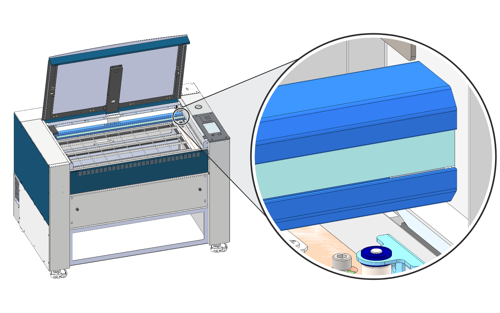
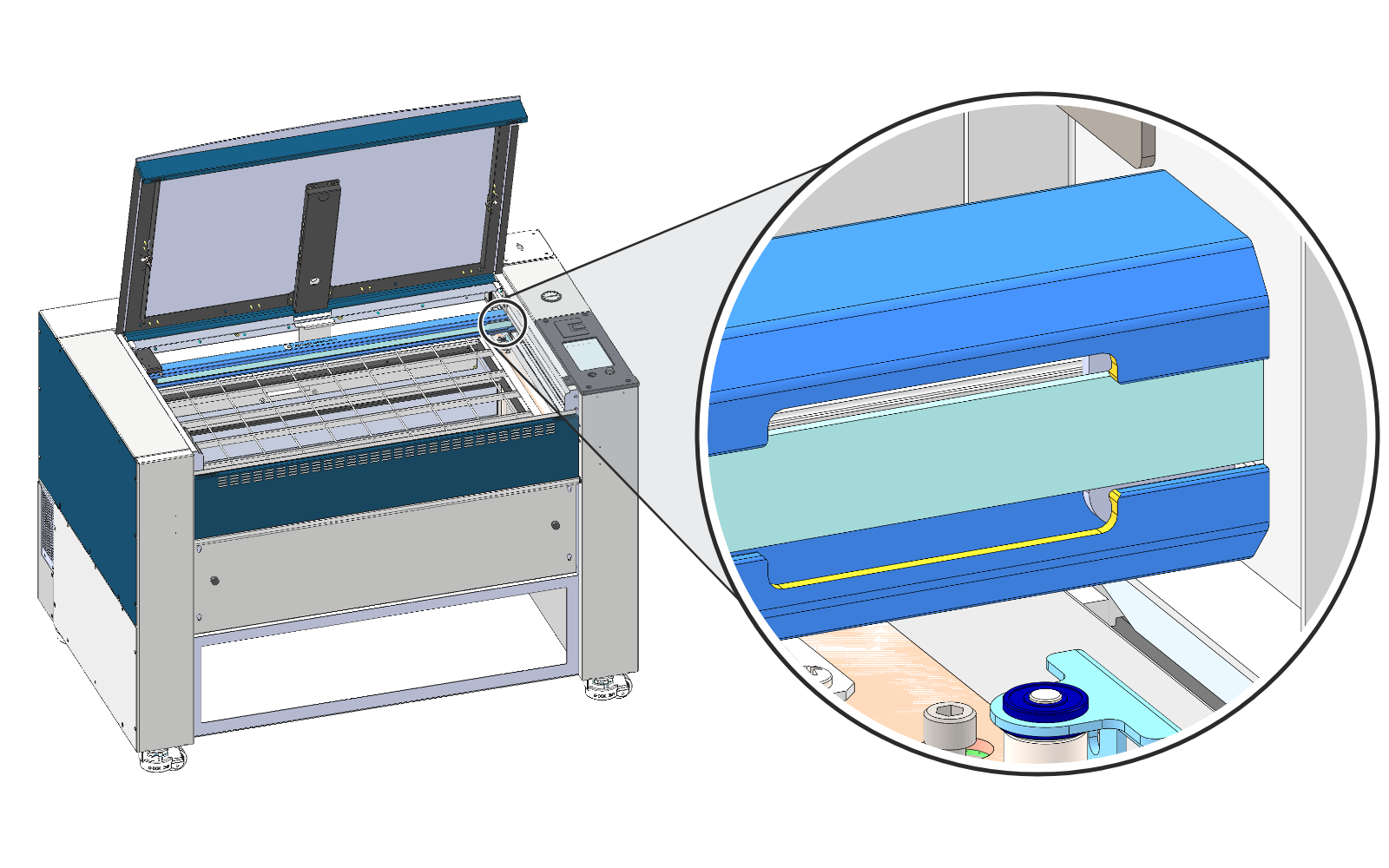
Open the top door and look at the right-hand end of the X-axis rail, where the belt runs. The Fusion Ascent always uses the Rev 2 procedure; its rail has small covers over the cutouts on the ends of the rail, so it may look a little different from the picture. Fusion Edge, Fusion Maker and Fusion Pro machines can have either. Select the rail that matches your machine.
-
Rev 1 Rail
No cutout in the rail at the right-hand end. On the left-hand end, the idler pulley sits in a bracket with two adjustment screws.
-
Rev 2 Rail
A cutout in the rail at the right-hand end. On the left-hand end, the idler pulley sits on a flat, black pivot arm with one adjustment screw. All Fusion Ascent machines use this procedure (the Ascent rail has small covers over the cutouts, so it may look a little different).
-
Select your rail above to show the steps for your machine.
-
Rev 1 Rail: Belt Tension and Tracking
Check the Tension
 Step 1
Turn Off the Engraver
Turn off the engraver and unplug it from its power source.
 Step 2
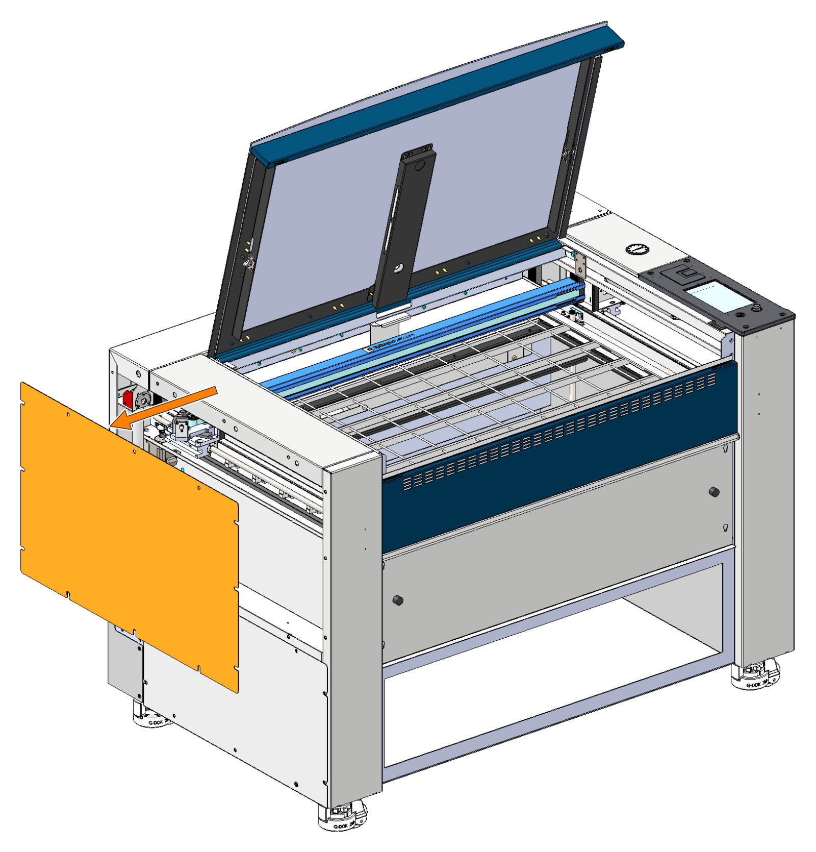
Remove the Left Side Panel
Remove the left-hand side panel to reach the left-hand end of the X-axis assembly.
 Step 3
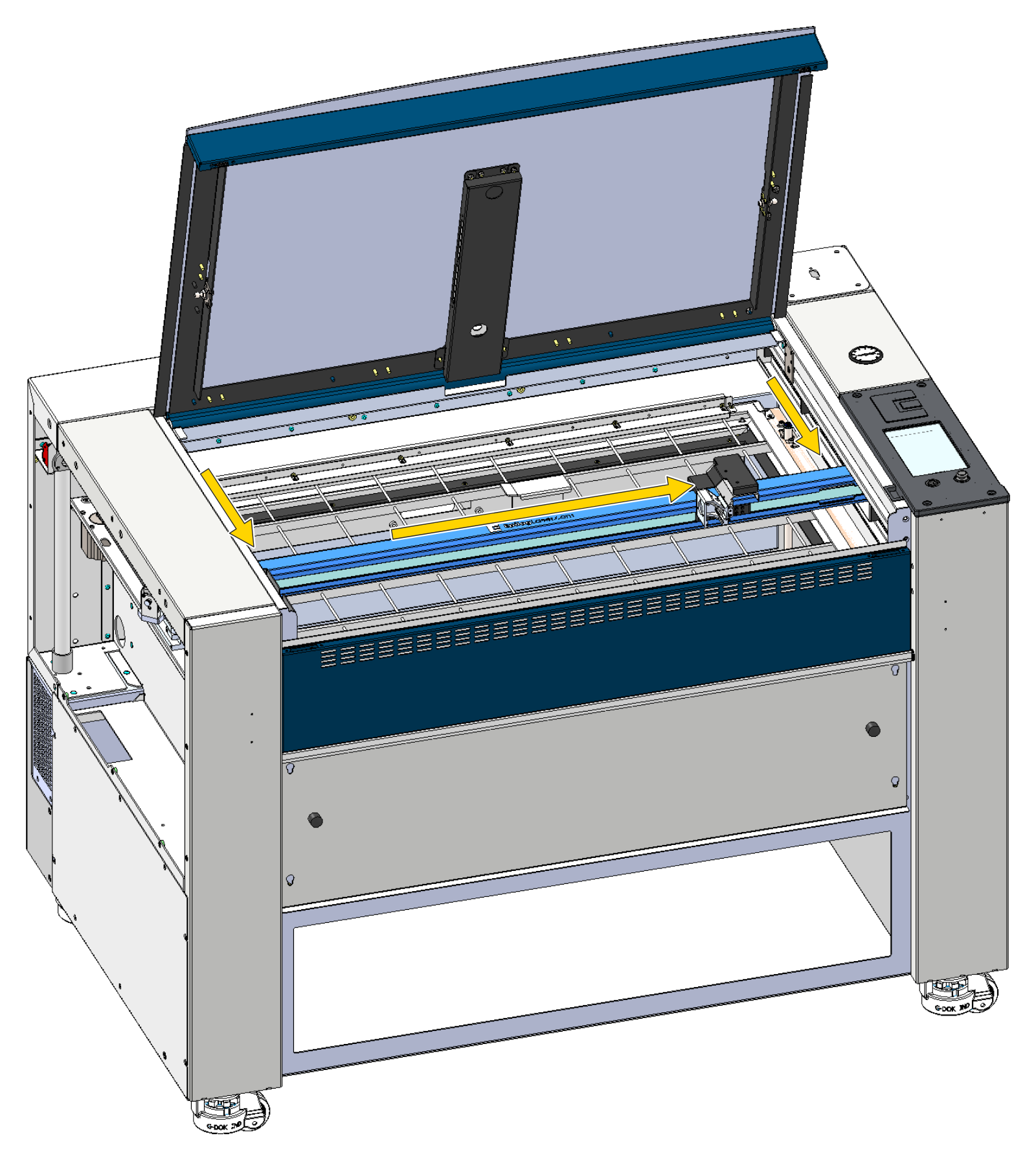
Position the Lens Carriage
Open the top door. By hand, slide the lens carriage to the right-hand side, and move the X-axis assembly toward the front, about halfway down the table.
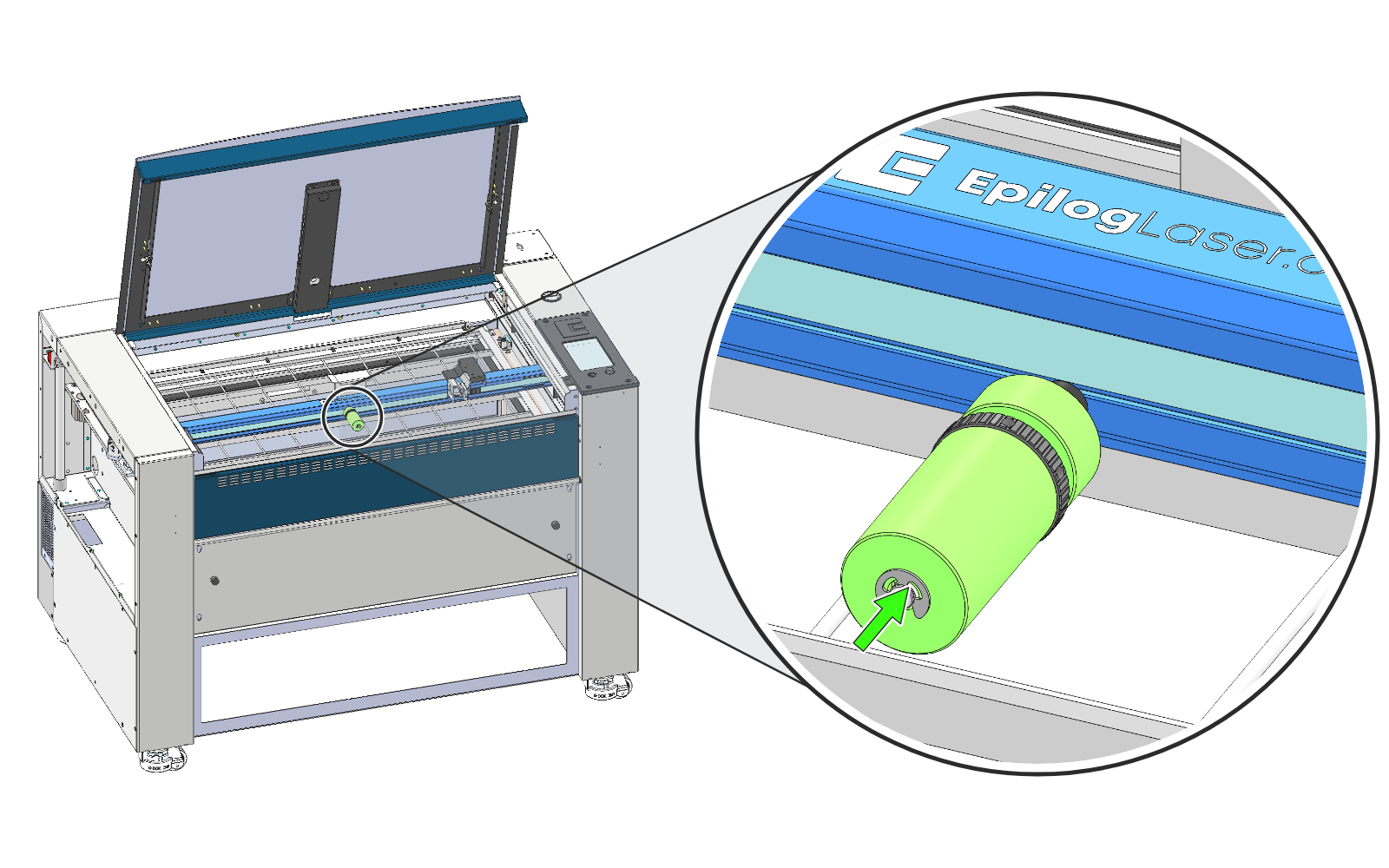 Step 4
Insert the Tensioning Tool
At the center of the X-axis assembly, push the tip of the belt tensioning tool into the opening in the front of the rail, against the X-axis belt.
Note: The notches on the tip of the tool must line up with the edges of the opening in the rail, where the belt runs. The tool only gives an accurate reading when it is seated this way.
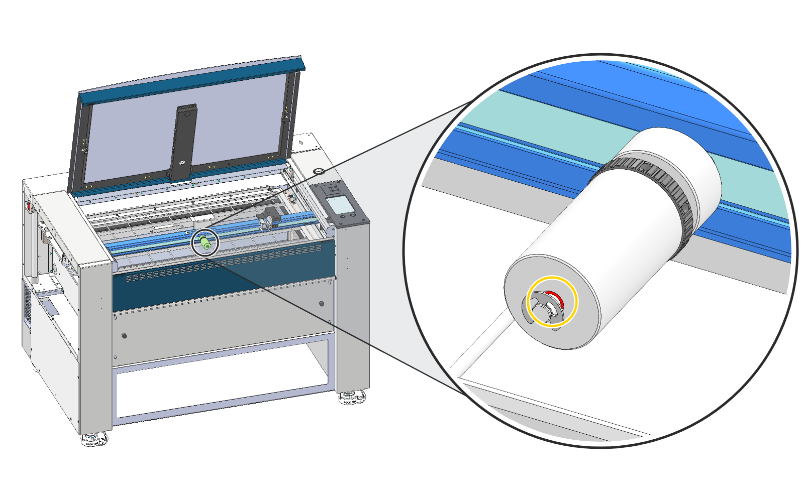 Step 5
Read the Belt Tension
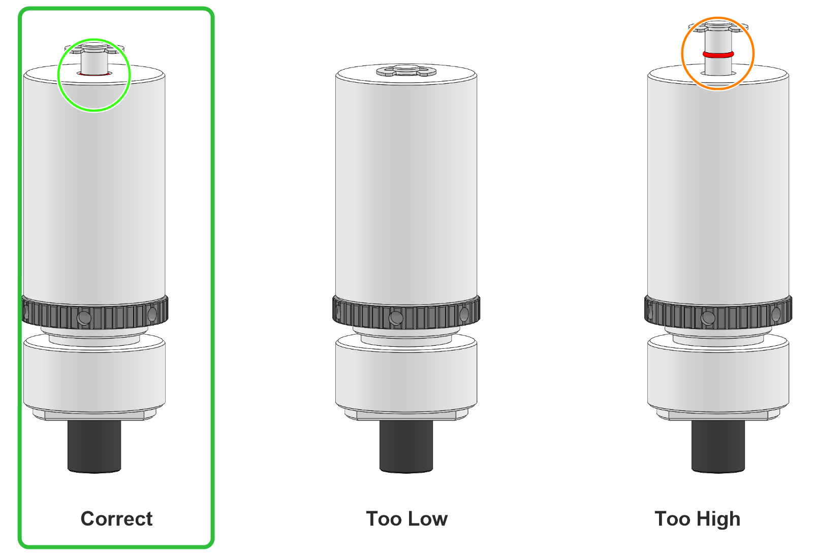
Hold the tool flush against the rail. The red O-ring on the rear shaft shows the belt tension:
- Correct: the O-ring is flush with the end of the tool.
- Too low: the O-ring is hidden inside the tool.
- Too high: there is a gap between the O-ring and the end of the tool.
See the three readings side by side.
Warning: Do not adjust the knurled ring on the tensioning tool. Each tool is calibrated at the factory.
Adjust the Tension
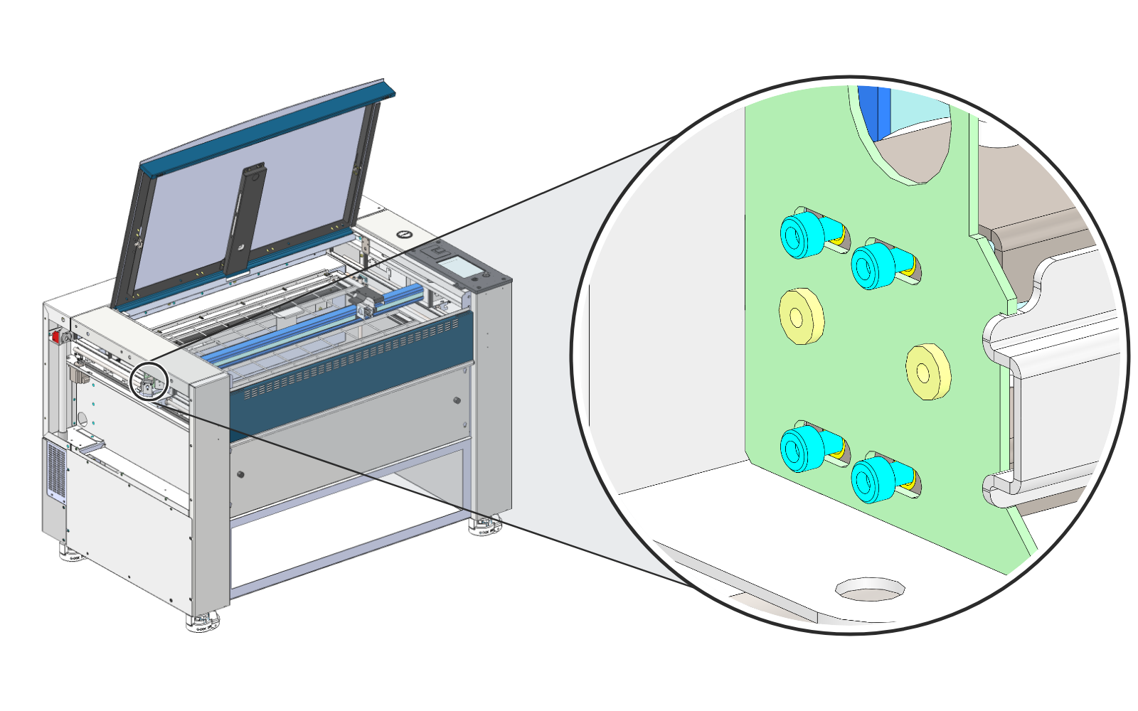 Step 6
Loosen the Rear Idler Screws
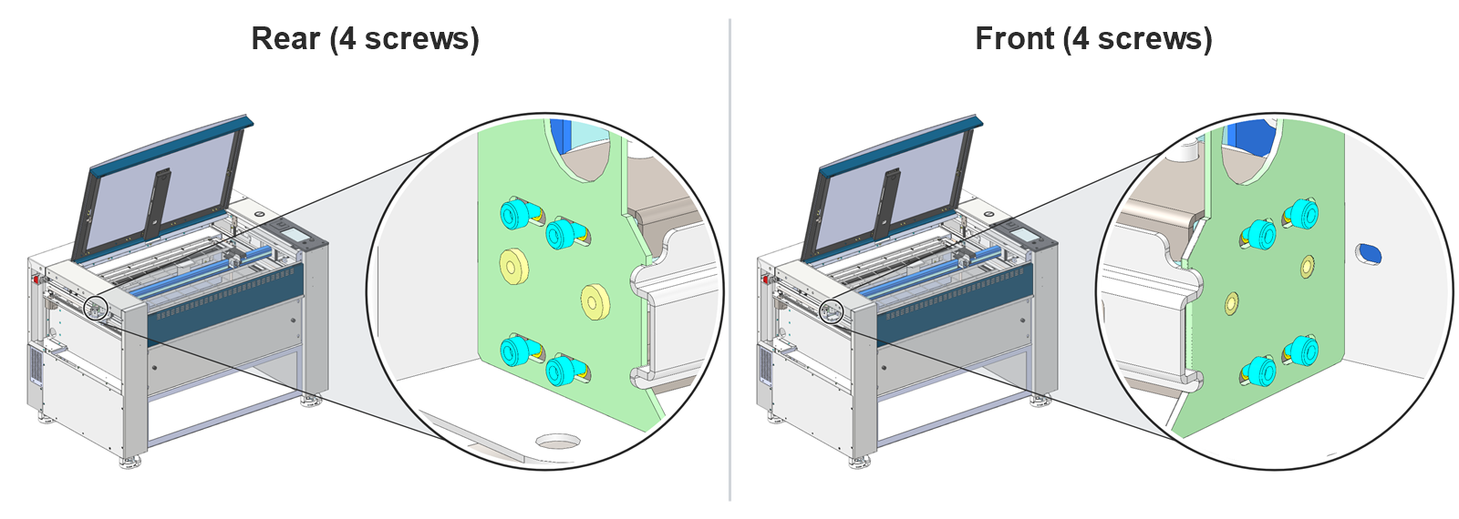
At the left-hand end of the X-axis assembly, loosen the four 7/64″ screws (blue) on the rear of the idler bracket. Loosen them just enough for the bracket to slide; do not remove them.
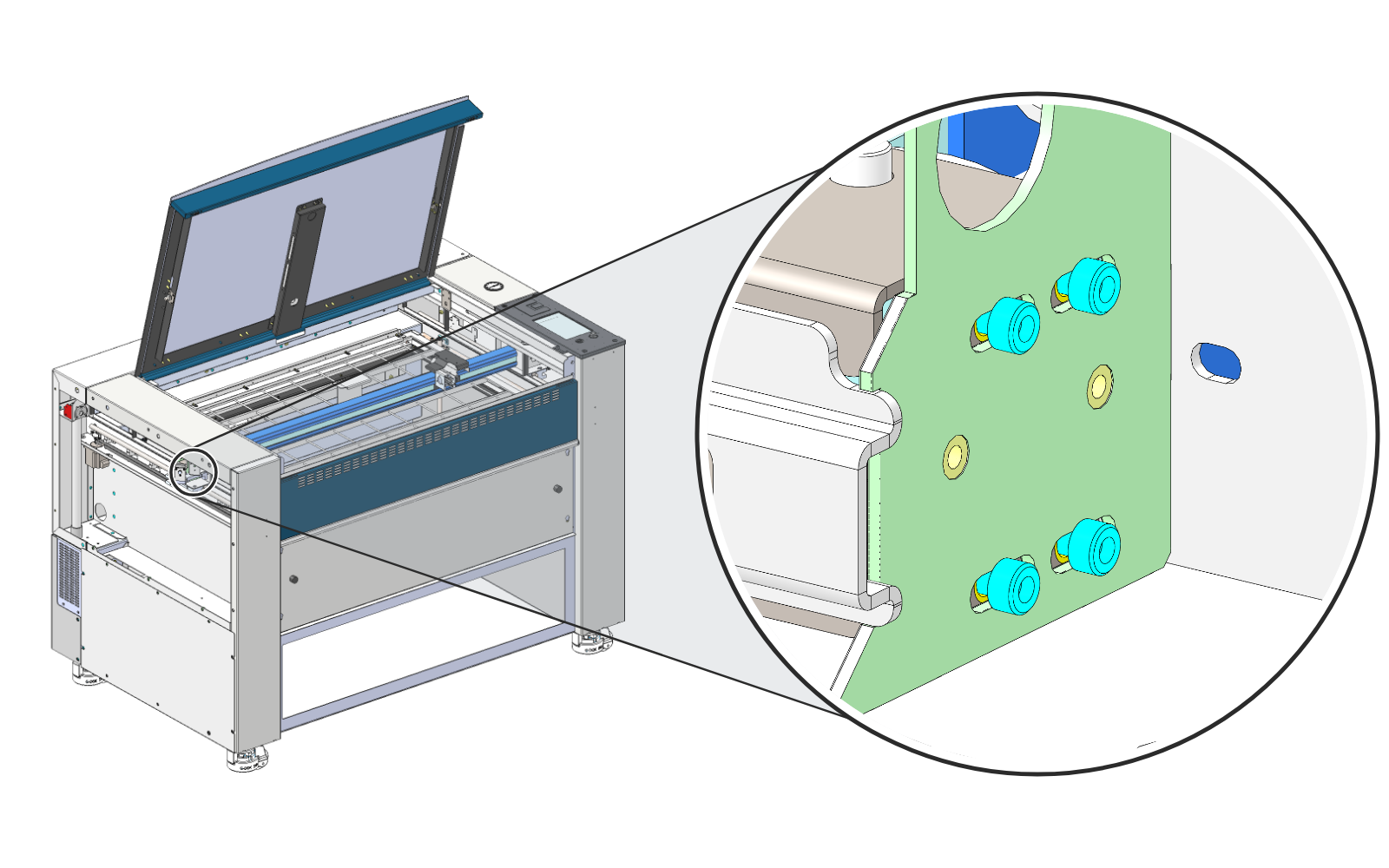 Step 7
Loosen the Front Idler Screws
Loosen the four 7/64″ screws (blue) on the front of the idler bracket the same way.
 Step 8
Adjust the Tension Screws
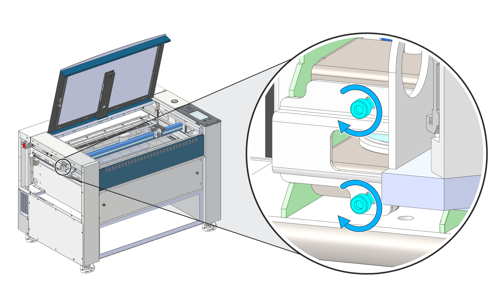
Turn the two 7/64″ tension screws (blue) on the end of the idler bracket evenly, the same amount each.
Note: Tightening these two screws adds tension to the belt. Loosening them removes tension.
Step 9Check the Tension Again
Repeat steps 4 and 5, checking the belt tension each time you turn the tension screws, until the O-ring is flush with the end of the tool.
Check the Belt Tracking
Step 10Create a Test Job
In your graphics software, create a black raster box about 2 inches narrower than the table and 4 inches tall.
Step 11Set Speed and Power
Set the job to 100% speed and 0% power.
Step 12Run the Job
Send the job to the engraver, open the top door, and start the job.
 Step 13
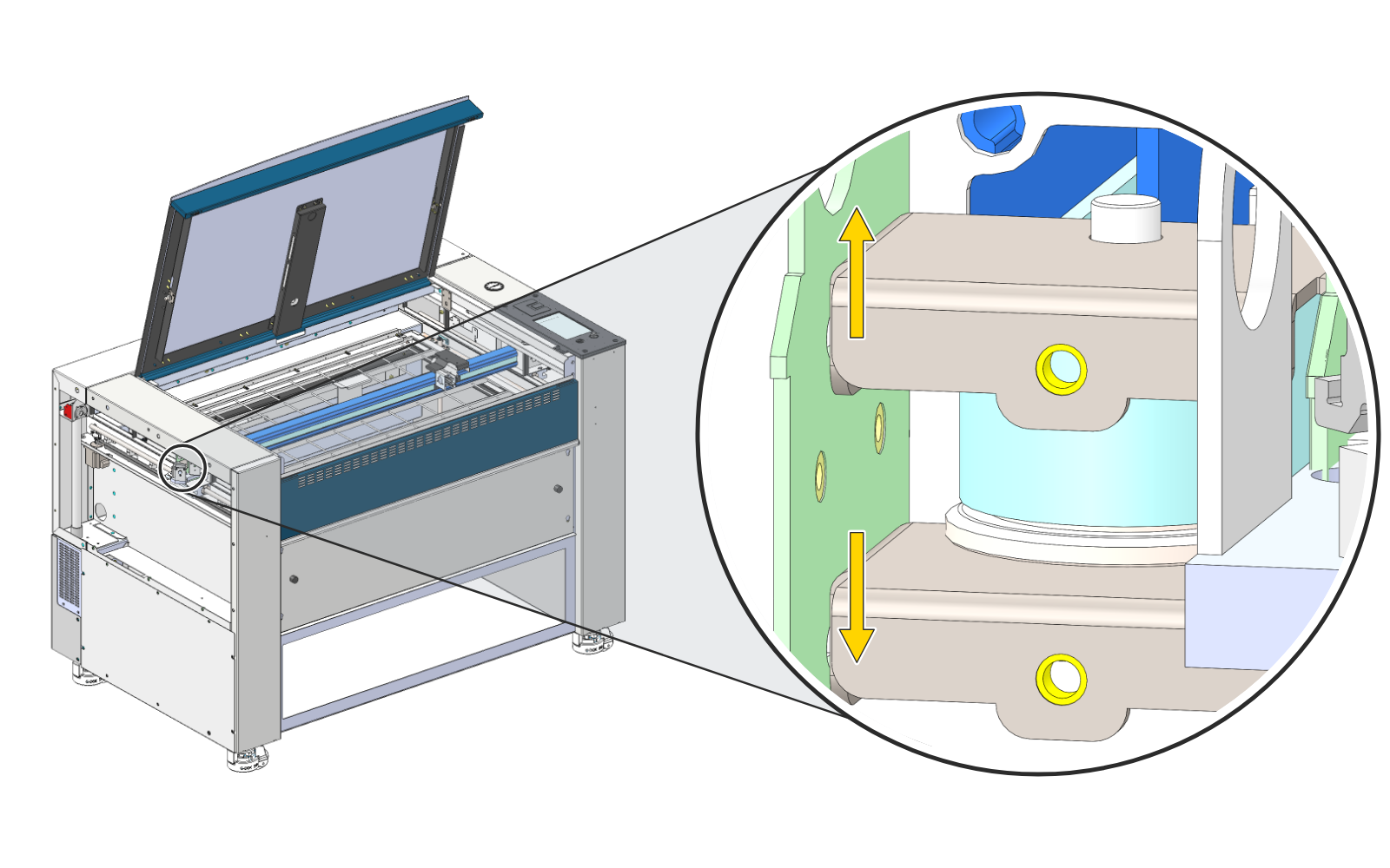
Watch the Belt on the Idler Pulley
As the lens carriage moves left and right, the belt should stay in the middle of the idler pulley, clear of both flanges.
 Step 14
Adjust the Tracking
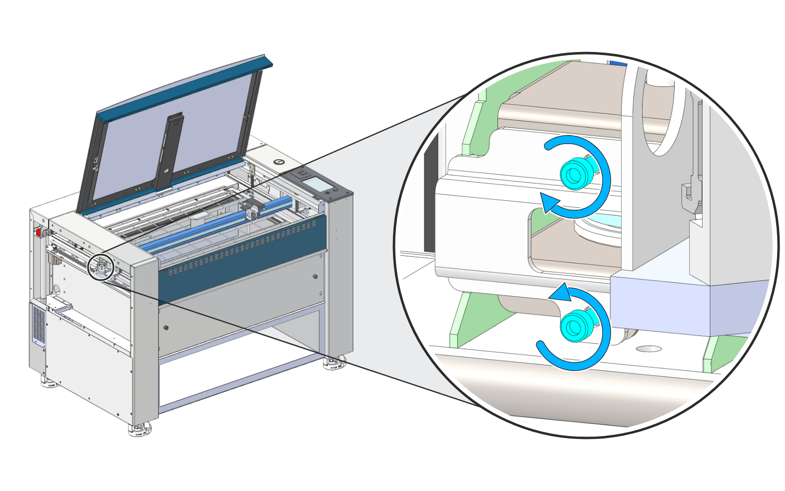
If the belt rides against a flange of the idler pulley, turn the two tension screws by equal but opposite amounts:
- Belt too high: tighten the top screw 1/4 turn and loosen the bottom screw 1/4 turn.
- Belt too low: loosen the top screw 1/4 turn and tighten the bottom screw 1/4 turn.
Step 15Check the Tension Again
When the belt tracks in the middle of the pulley, check the belt tension again (steps 4 and 5). Adjust it if needed (step 8).
 Step 16
Tighten the Idler Screws
With the tension and tracking set, tighten the eight 7/64″ screws (blue), four on the rear and four on the front of the idler bracket, to lock it in place.
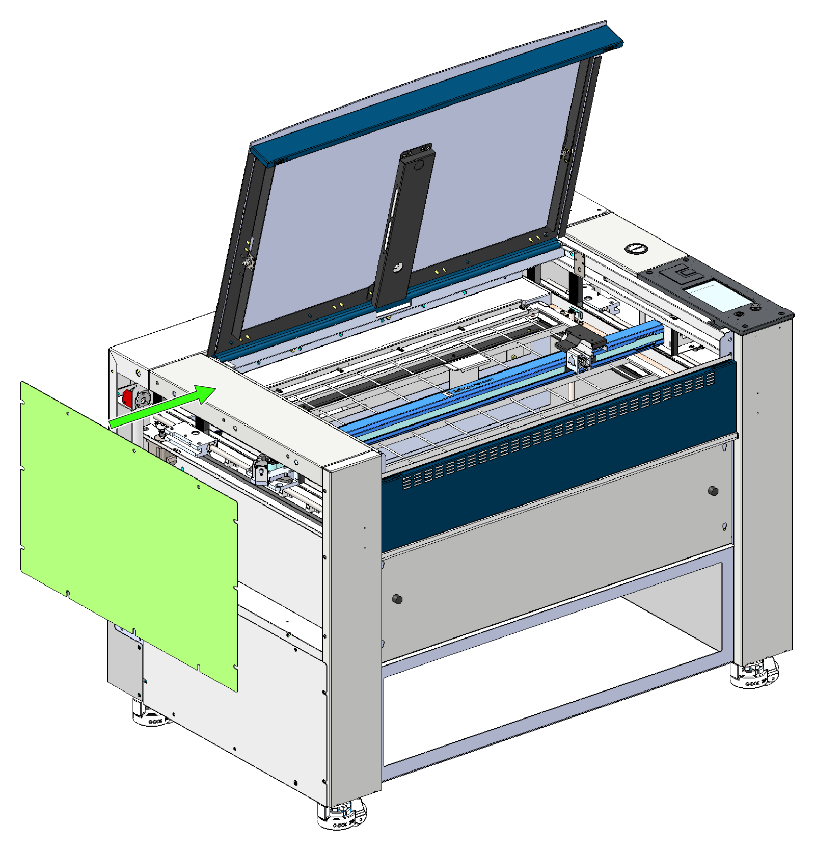 Step 17
Install the Left Side Panel
Install the left-hand side panel and close the top door.
-
Rev 2 Rail: Belt Tension
Note: Fusion Ascent owners: your machine uses these Rev 2 steps. The Ascent rail has small covers over the cutouts on the ends of the rail, so it may look a little different from the pictures; the tool and adjustments are the same.
Check the Tension
Step 1Turn Off the Engraver
Turn off the engraver and unplug it from its power source.
Step 2Remove the Left Side Panel
Remove the left-hand side panel to reach the left-hand end of the X-axis assembly.
Step 3Position the Lens Carriage
Open the top door. By hand, slide the lens carriage to the right-hand side, and move the X-axis assembly toward the front, about halfway down the table.
Step 4Insert the Tensioning Tool
At the center of the X-axis assembly, push the tip of the belt tensioning tool into the opening in the front of the rail, against the X-axis belt.
Note: The notches on the tip of the tool must line up with the edges of the opening in the rail, where the belt runs. The tool only gives an accurate reading when it is seated this way.
Step 5Read the Belt Tension
Hold the tool flush against the rail. The red O-ring on the rear shaft shows the belt tension:
- Correct: the O-ring is flush with the end of the tool.
- Too low: the O-ring is hidden inside the tool.
- Too high: there is a gap between the O-ring and the end of the tool.
See the three readings side by side.
Warning: Do not adjust the knurled ring on the tensioning tool. Each tool is calibrated at the factory.
Adjust the Tension
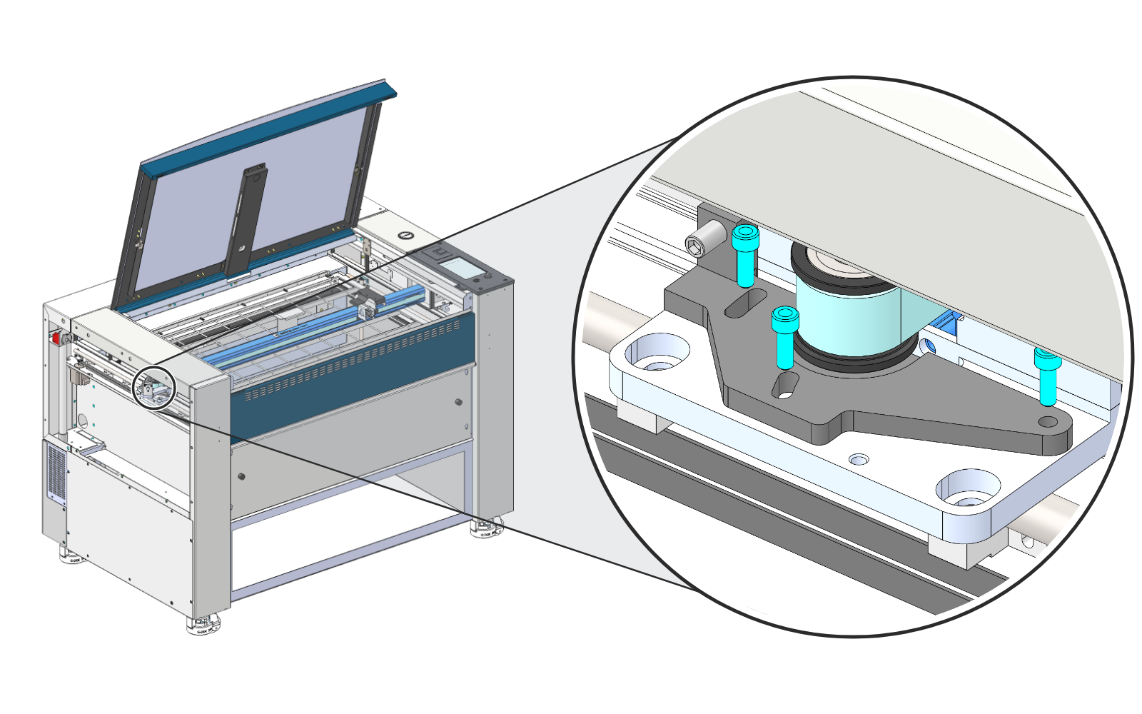 Step 6
Loosen the Tensioner Screws
At the left-hand end of the X-axis assembly, loosen the three 5/32″ screws (blue) on the tensioner arm. Loosen them just enough for the arm to pivot; do not remove them.
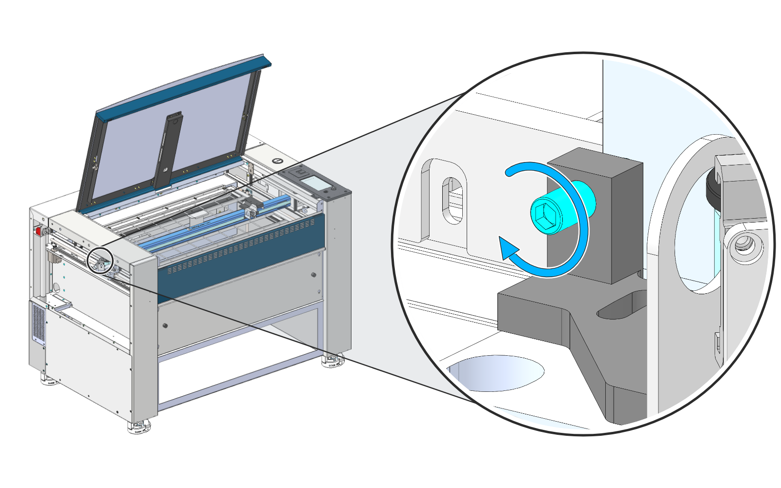 Step 7
If the Tension Is Low
Turn the 5/32″ tensioner adjustment screw (blue) clockwise to add tension.
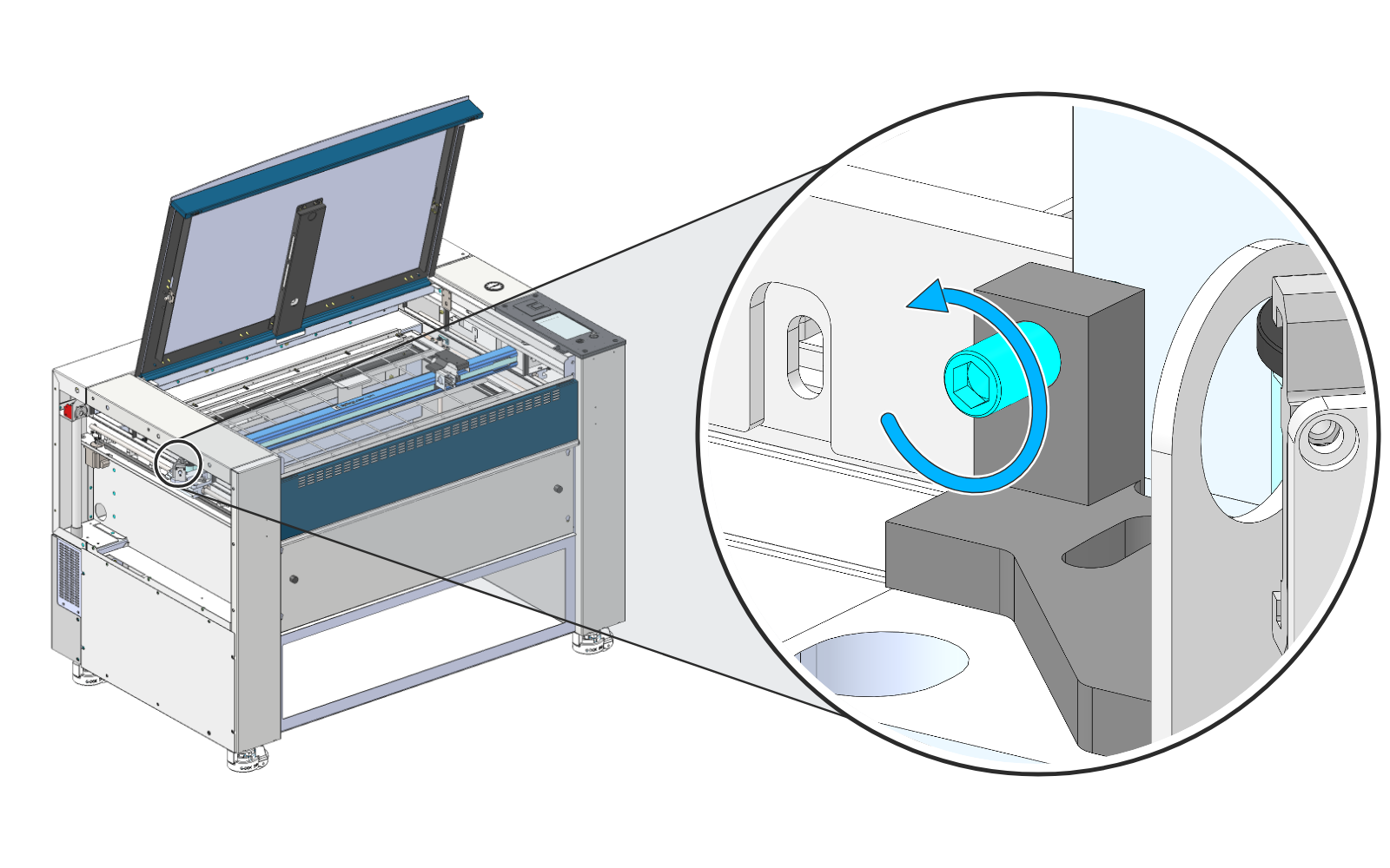 Step 8
If the Tension Is High
Turn the adjustment screw (blue) counterclockwise to remove tension.
Step 9Check the Tension Again
Repeat steps 4 and 5, checking the belt tension each time you turn the adjustment screw, until the O-ring is flush with the end of the tool.
Step 10Tighten the Tensioner Screws
When the tension is correct, tighten the three 5/32″ screws (blue) on the tensioner arm.
Step 11Install the Left Side Panel
Install the left-hand side panel and close the top door.