
Estimated time: 20–30 minutes • Skill: Intermediate
This procedure explains how to square the Y-Axis rails on 16K-series laser systems. Proper squaring ensures smooth motion, accurate engraving, and prevents premature wear on the motion system components.
Y-Axis Squaring Procedure
-
Power off and disconnect the machine.
Shut down the laser system and unplug the power cable to prevent accidental motion or electrical hazards during adjustment.
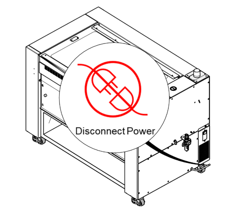
Figure 1: Power down and disconnect the machine. -
Remove the exhaust plenum.
Using a 5/32″ Hex wrench, remove the mounting screws securing the exhaust plenum to the rear of the machine. Set the plenum and hardware aside.
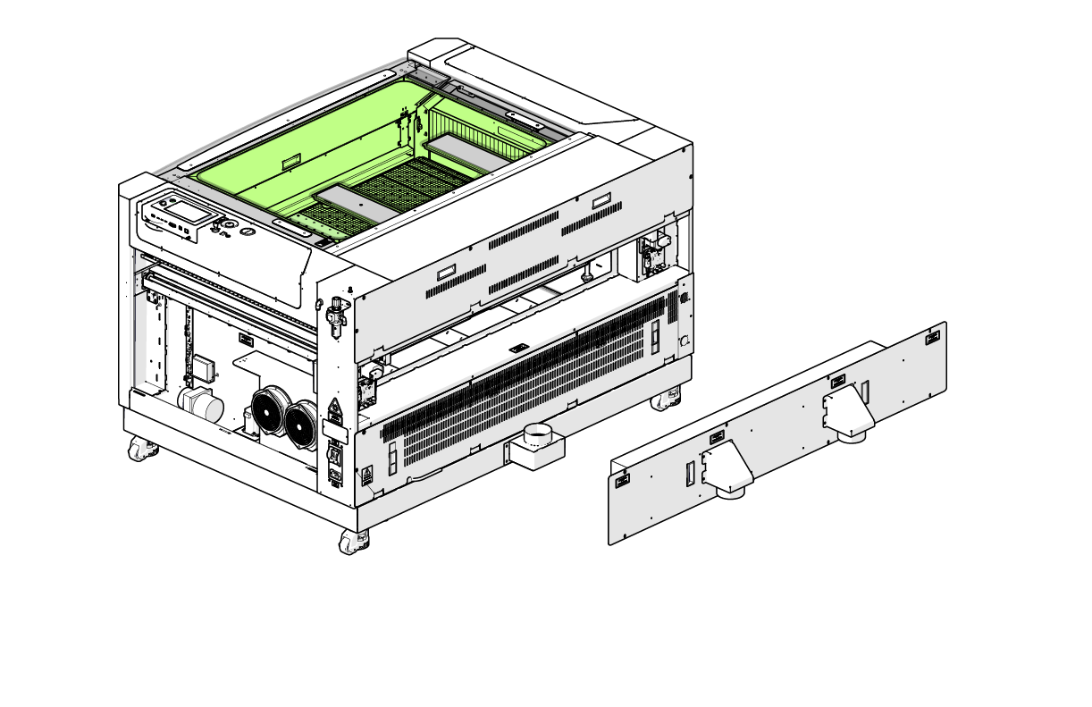
Figure 2: Remove the rear exhaust plenum. -
Remove the right-hand side panel.
Using a 5/32″ Hex wrench, remove the fasteners securing the right-side access panel, then carefully lift the panel away from the machine.
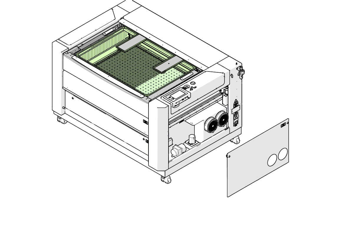
Figure 3: Remove the right-hand side panel. -
Loosen the front right Y-Axis actuator screws.
Using a 7/64″ Hex wrench, loosen—but do not remove—the three (3) Hex screws securing the right Y-Axis actuator to the front of the machine chassis.
These screws must remain installed to allow controlled movement during squaring.
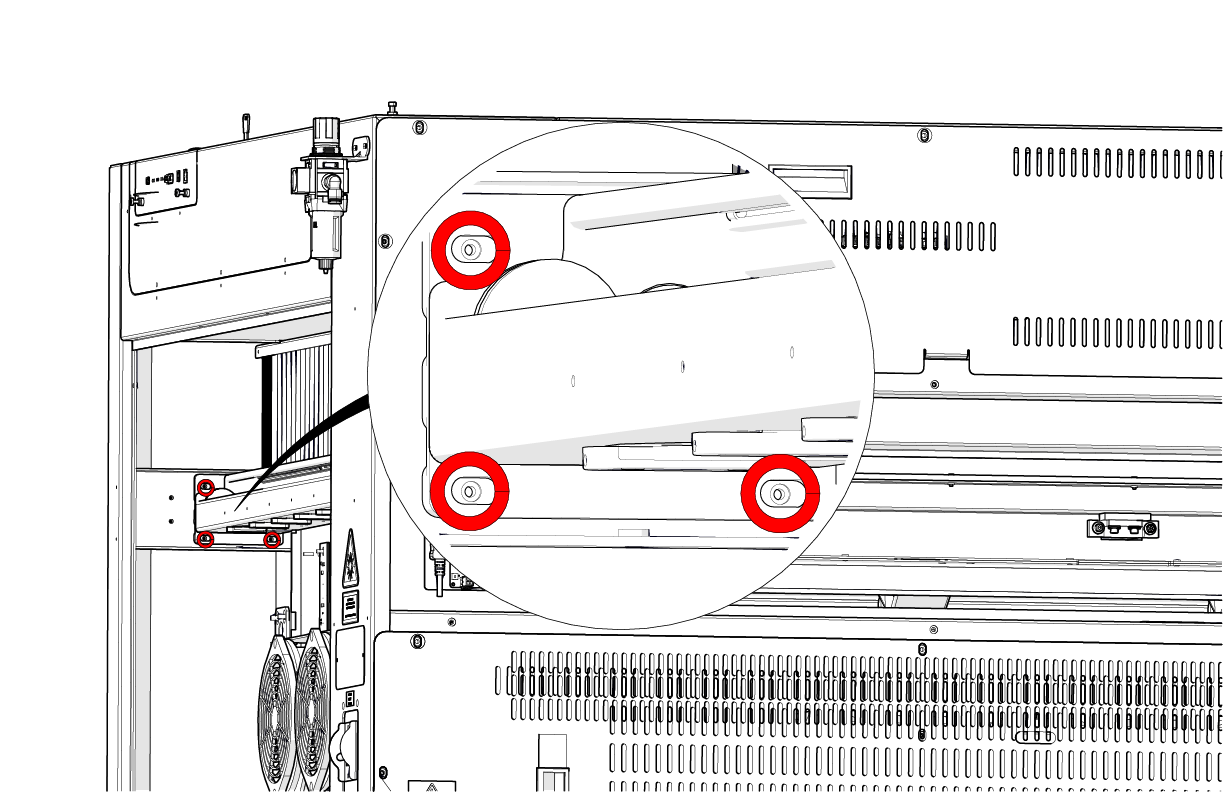
Figure 4: Loosen the front Y-Axis actuator mounting screws. -
Loosen the right-rear Y-Axis actuator screws.
Using a 7/64″ Hex wrench, loosen—but do not remove—the four (4) Hex screws securing the right Y-Axis actuator to the rear of the machine chassis.
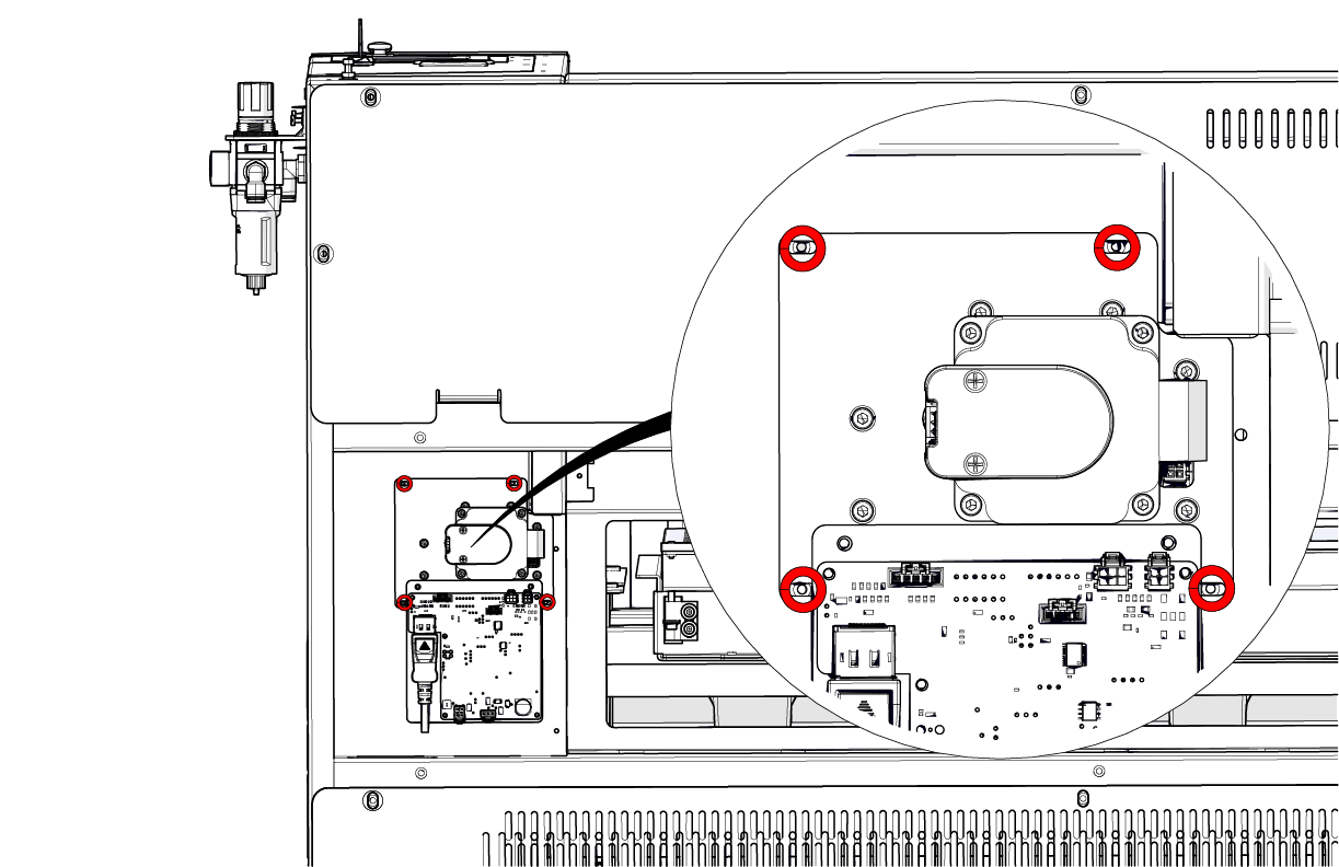
Figure 5: Loosen the rear Y-Axis actuator mounting screws. -
Move the X-Axis assembly to the front of the engraver.
Carefully slide the X-Axis assembly forward until it reaches the front of the machine. Ensure the gantry is square and evenly aligned with the frame of the engraver.
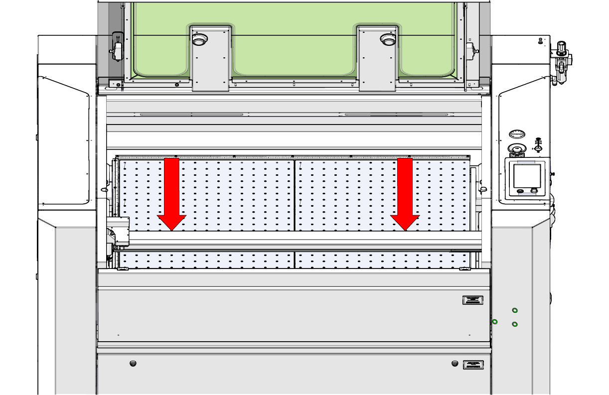
Figure 6: Position the X-Axis assembly at the front of the machine. -
Tighten the front Y-Axis actuator screws.
While holding the X-Axis assembly square, use the 7/64 ” Hex wrench to fully tighten the three (3) front mounting screws securing the right Y-Axis actuator.
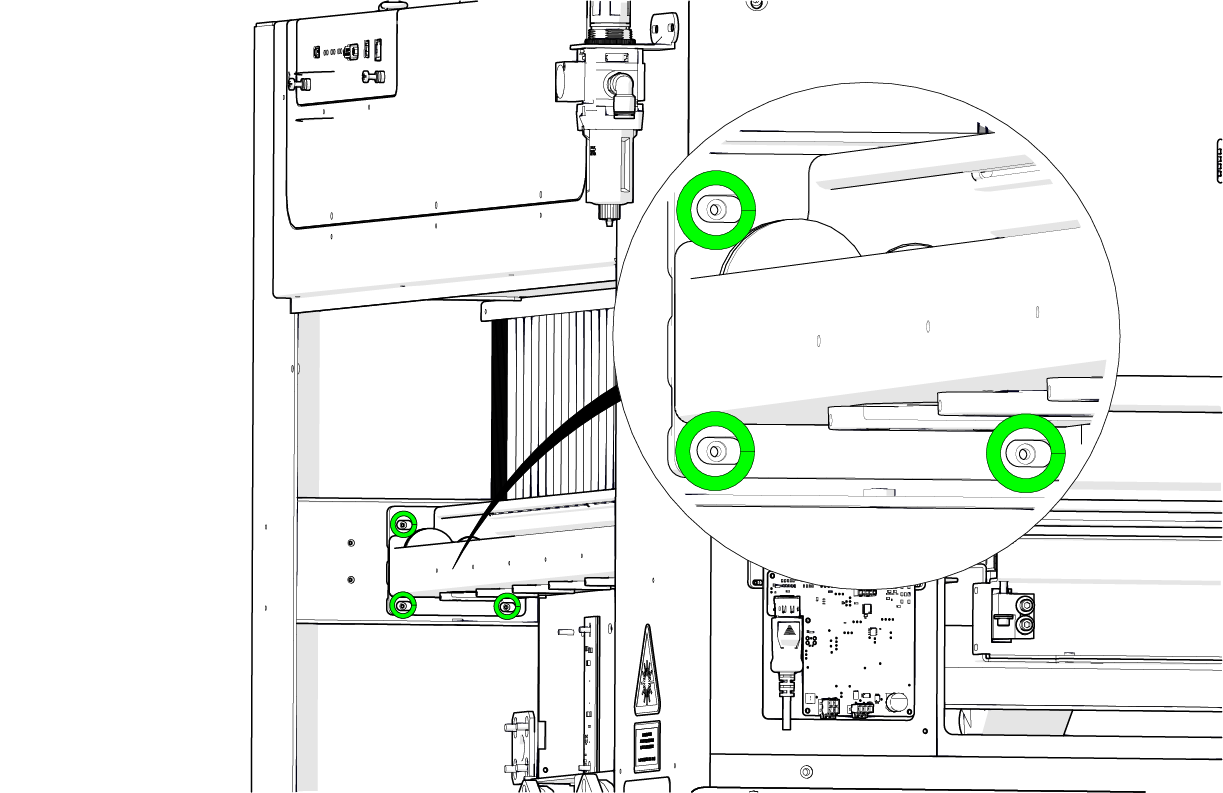
Figure 7: Tighten the front Y-Axis actuator mounting screws. -
Move the X-Axis assembly to the rear of the engraver.
Manually slide the X-Axis assembly toward the rear of the machine. Verify that it is square to the rear frame.
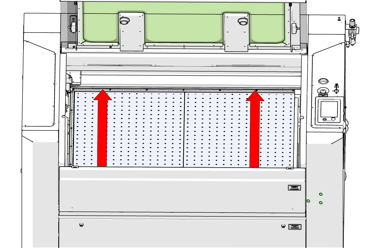
Figure 8: Position the X-Axis assembly at the rear of the machine. -
Tighten the rear Y-Axis actuator screws.
Using the 7/64″ Hex wrench, fully tighten the four (4) rear mounting screws securing the right Y-Axis actuator to the chassis.
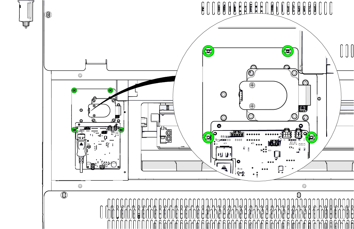
Figure 9: Tighten the rear Y-Axis actuator mounting screws.
After completing this procedure, reinstall the right-side panel and exhaust plenum, then reconnect the machine to power.
