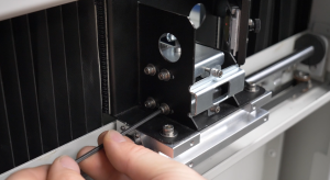
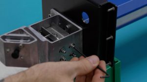
This guide covers replacing the x-axis drive board on the Fusion Pro 32 and 48. The board is mounted in the housing on the right end of the x-axis assembly. After installation, the motor drives and FPGA are updated from the display.
Parts Required
- TE0104 – PCB, Servo Motor Drive
Tools / Materials Required
- 5/32" Allen Wrench
- Phillips Screwdriver
- Anti-Static Strap
Safety First: Ensure the engraver is completely powered off and the power cord is disconnected before removing any panels or touching internal components.
X-Axis Drive Board Removal
Turn Off Engraver
Turn off the engraver.
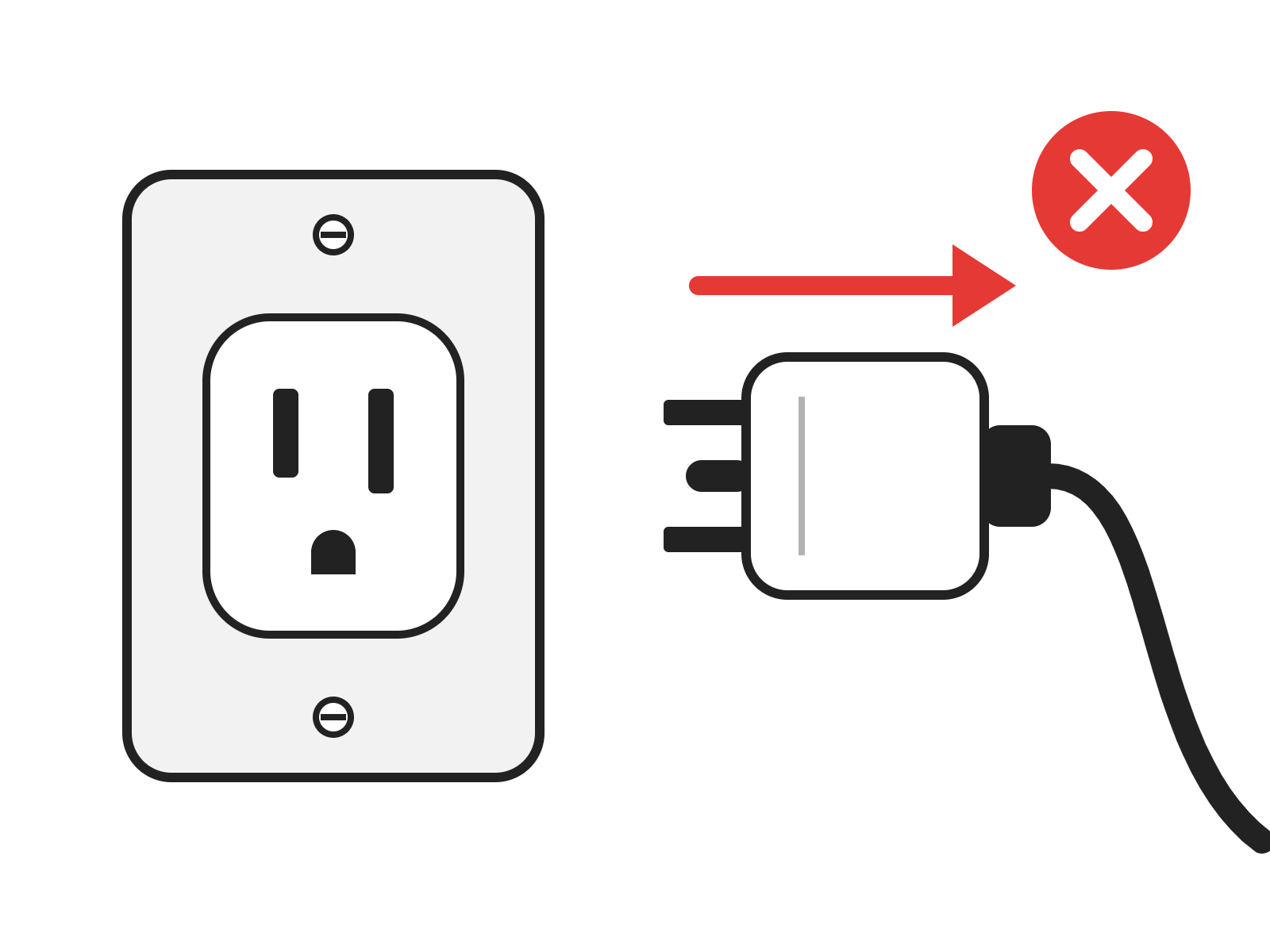
Disconnect from Power
Unplug the engraver from its power source.
Remove Right Panel
Remove the right panel of the engraver.
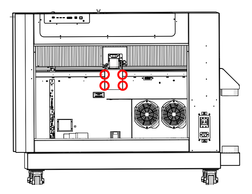
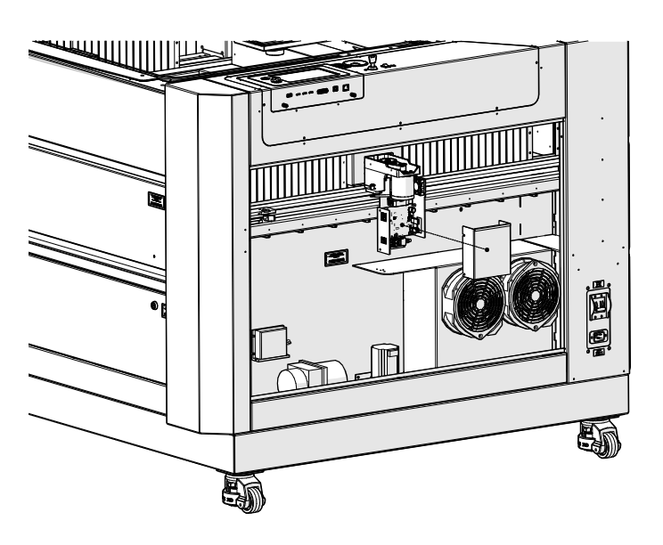
Loosen Cover Screws
Loosen, but do not remove, the four Phillips screws on the x-axis drive board cover (circled in red).
Remove the Cover
Remove the x-axis drive board cover.
Put On Anti-Static Strap
Place the anti-static strap around your wrist and attach the clamp to a bare metal surface in the engraver.
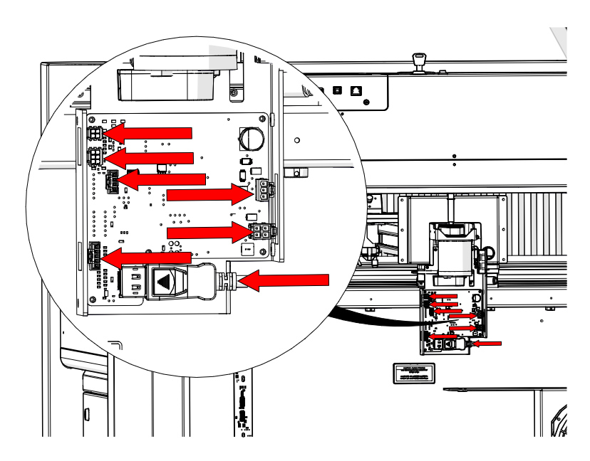
Disconnect Connectors
Disconnect the seven electrical connectors from the drive board (red arrows).
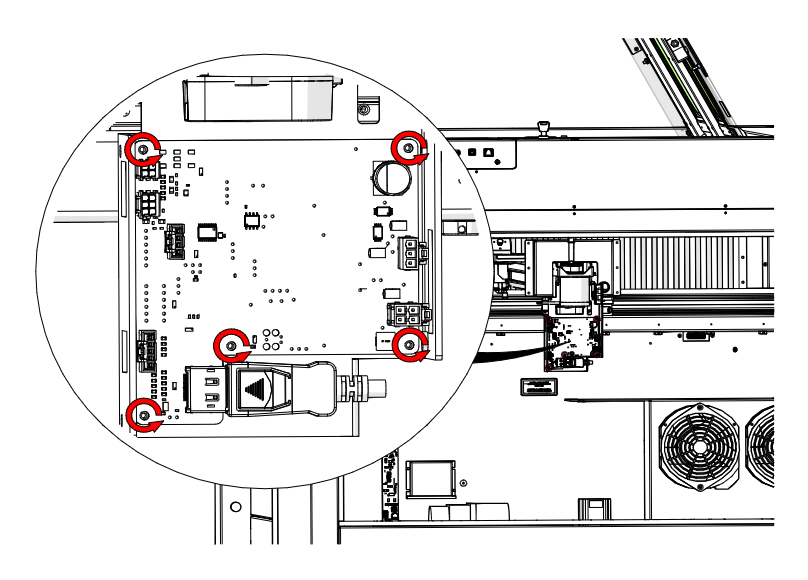
Remove Board Screws
Remove the five Phillips screws that secure the drive board to the housing (circled in red).
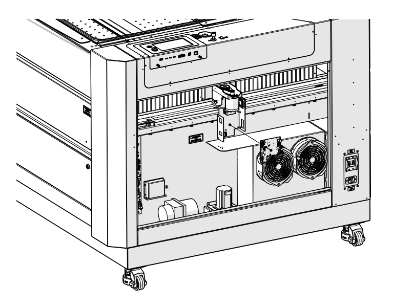
Remove the Drive Board
Remove the x-axis drive board from the housing.
X-Axis Drive Board Installation
Install the New Drive Board
Place the new TE0104 drive board in the housing and install the five Phillips screws that secure it.
Connect Connectors
Connect the seven electrical connectors to the drive board.
Note: Each connector on the drive board is unique and only fits one receptacle.
Install the Cover
Install the x-axis drive board cover and tighten the four Phillips screws.
Install Right Panel
Install the right panel of the engraver.
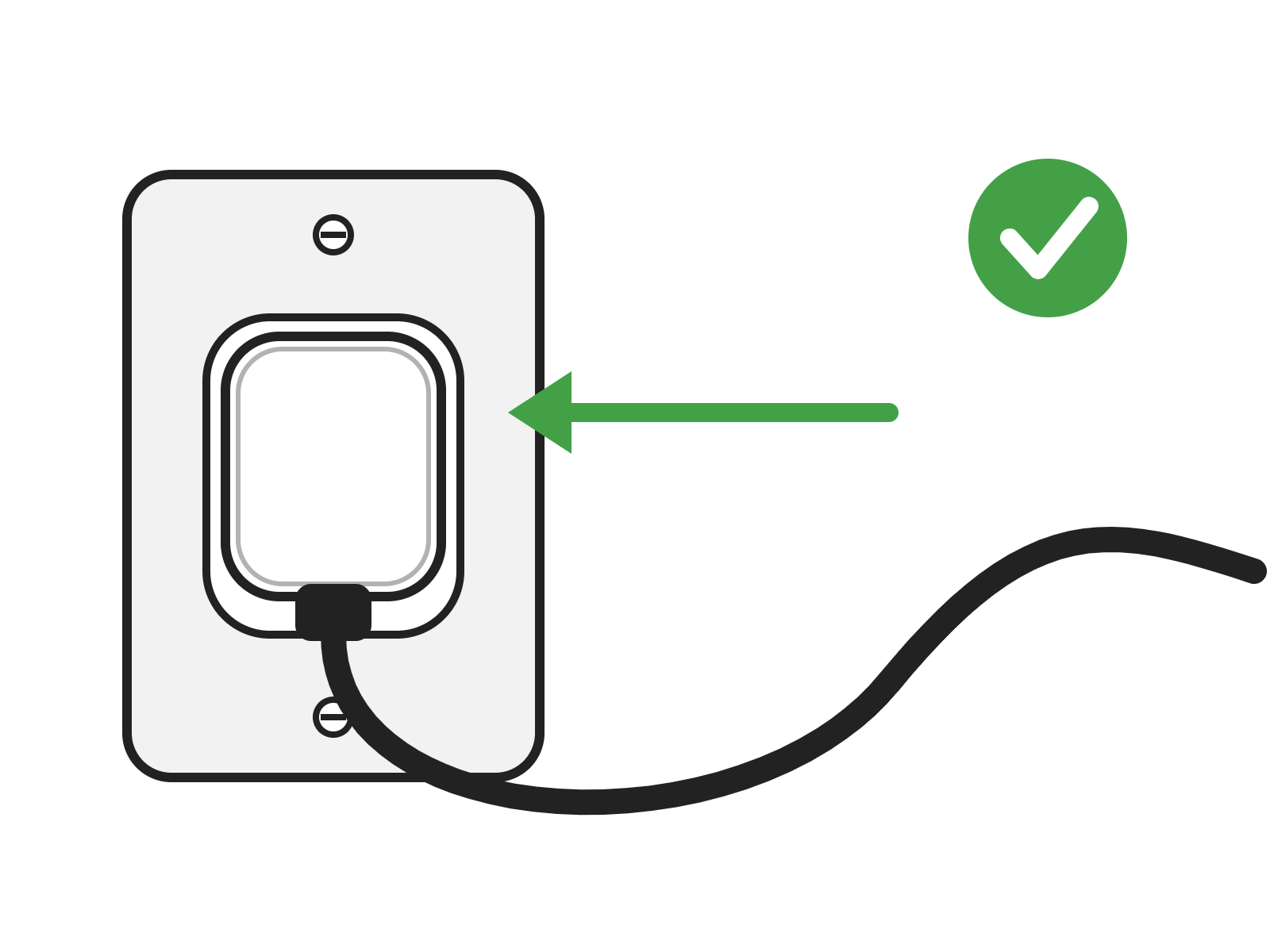
Power On
Reconnect the engraver to power and turn it on.
Program the X-Axis Drive Board

Open the Settings Menu
On the display, press the gear icon in the upper right corner to open the Settings menu.
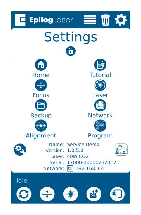
Open Peripheral Update
Press Program to open the Peripheral Update menu.
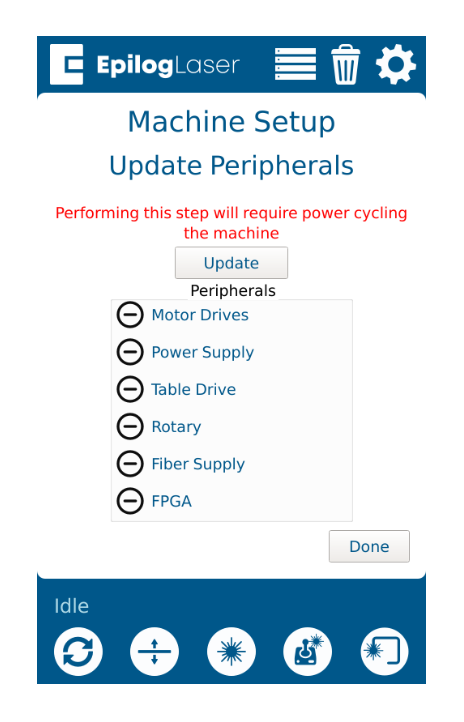
Update Motor Drives and FPGA
Select Motor Drives and FPGA, then press Update.
Let the Update Run
Let the engraver run the update. When the update has been applied, the engraver prompts you to restart.
Important: Do not power off the engraver during the update. It is normal for the display to turn off while the update runs.
Restart When Prompted
When the engraver prompts you to restart, power cycle the engraver.