
This guide covers aligning the laser on the Legend 36EXT: lining up the red dot pointer with the laser, aligning through the periscope tube when needed, and aligning the three mirrors.
Parts Required
- None
Tools / Materials Required
- Phillips Screwdriver
- 3/32" Allen Wrench
- Masking Tape
- Alignment Target (supplied with the engraver)
- Two-part epoxy or metal-safe glue
Laser Safety: The laser fires during this procedure. Make sure no one is standing behind the engraver, and keep the doors closed when firing.
Before You Start
- Level the engraver first, following the Table Leveling Procedure for the Legend 36EXT.
- Put the engraver where it will stay. Moving it after alignment can throw the alignment off, so leave room to reach both sides and to remove the rear panels.
- Keep the large door closed while making any adjustment. Adjustments made with the door open move when the door is shut.
Checking the Red Dot and Laser
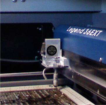
Install the Target
Fit the alignment target that came with your engraver into the hole at the upper left of the lens carriage, facing the right side of the engraver.
Enter Align Laser Mode
Press MAINT, use the arrow keys to scroll to Align Laser and press GO. The display reads Press up key to fire laser.
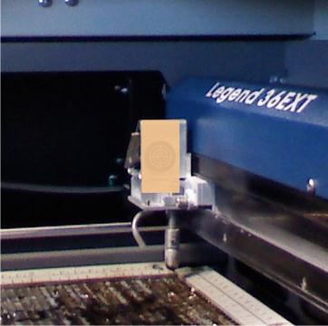
Tape the Target
Place a piece of masking tape over the target.
Move to Position 4
Move the lens carriage to position 4, the front left corner of the engraver.
Close the Doors
Close the access doors. In Align Laser mode the laser will not fire with the doors open.
Fire the Laser
Press the Up arrow a couple of times to fire the laser. You only need a small burn mark in the tape.
Note: If the burn mark is deformed and looks like a half moon, go to Aligning Through the Periscope Tube. If you cannot get a burn mark in this position, contact Epilog Technical Support.
Turn On the Red Dot
Press POINTER to turn on the red dot pointer.
Note: If the red dot is deformed or looks very elongated, go to Aligning Through the Periscope Tube.
Compare the Red Dot and Burn
Check whether the red dot sits on top of the burn mark. If it does, skip to Aligning the Mirrors. If not, continue with the next steps to adjust the red dot.
Remove the Laser Cover
The back of the engraver has three panels. Remove the middle one, the laser cover directly below the air ducts, by taking out its 11 #1 Phillips screws.
Locate the Red Dot Pointer
The laser assembly is behind the cover. The red dot pointer mount is on the left side of the laser assembly as you face the back of the engraver. The pointer is a small cylinder with red and black wires, held in a mount with three Allen screws that is flat on one side and round on the other.
Adjust the Red Dot
Use the three Allen screws around the pointer to move the red dot to the center of the burn mark, using the guide below. Try to use the two screws closest to you.
Important: If you use the screw on the back of the mount, do not let the Allen wrench touch the screw and the diode at the same time. That can short the pointer and restart the engraver, and you would need to repeat steps 2–7.
Red Dot Screw Guide: Pointer on Top of the Laser
Screws as seen from the back of the engraver.
- Far left screw: clockwise moves the dot right; counterclockwise moves it left.
- Front right screw: clockwise moves the dot to the upper left; counterclockwise moves it to the lower right.
- Back right screw: clockwise moves the dot to the lower left; counterclockwise moves it to the upper right.
Red Dot Screw Guide: Pointer on the Bottom of the Laser
Screws as seen from the back of the engraver.
- Far left screw: clockwise moves the dot left; counterclockwise moves it right.
- Front right screw: clockwise moves the dot to the upper right; counterclockwise moves it to the lower left.
- Back right screw: clockwise moves the dot to the lower right; counterclockwise moves it to the upper left.
Red Dot Aligned
With the red dot on the center of the burn mark, it can now be used as the guide for the rest of the alignment.
Aligning Through the Periscope Tube
Only do this section if the burn mark looked like a half moon or the red dot was elongated. Otherwise, skip to Aligning the Mirrors.
Remove the Panels
Remove the rear panels above and below the exhaust ducts, the right side panel, and the small panel at the top right of the back of the engraver. That small panel covers a black or red thumb screw with three Allen screws around it.
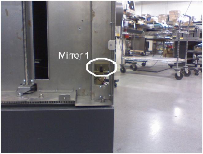
Locate Mirror 1
From the right side of the engraver, look through the rectangular cutout in the lower right corner of the frame. The thumb screw with three Allen screws in a triangle around it holds the mirror 1 adjustment screws.
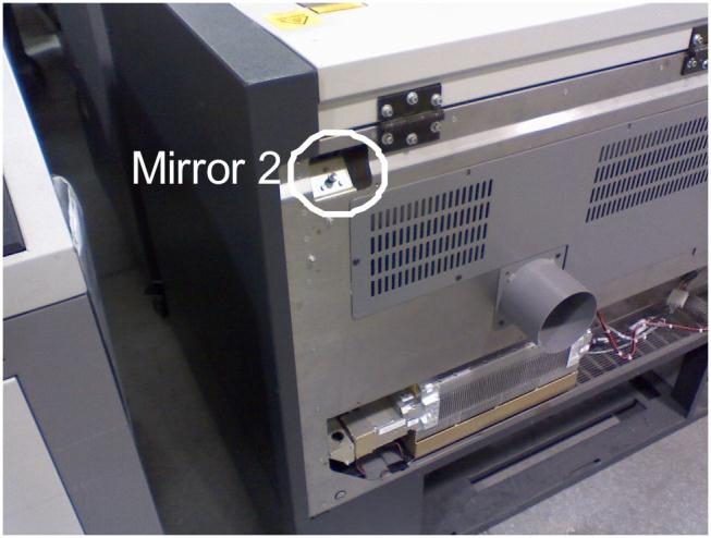
Locate Mirror 2
The mirror 2 adjustment screws are behind the small panel you removed from the top right of the back. The periscope tube runs between mirror 1 and mirror 2.
Remove the Mirror 2 Housing
From the right side of the engraver, remove the three shiny Phillips screws holding the mirror 2 housing. Pull the housing back and lift it out.
Remove the Periscope Tube
Lift the periscope tube out.
Tape the Mirror Housing
On the bottom of the mirror housing, find where the periscope tube fitted in. Put a piece of masking tape over that hole.
Reinstall the Housing
Hold the mirror housing in place (or have a second person hold it) and reinstall its three silver screws.
Make a Test Burn
Press MAINT, then the Down arrow to Align Laser, then GO. Make sure no one is standing behind the engraver, press the Up arrow once quickly, then open the lid and check the tape for a burn mark.
Center the Burn With Mirror 1
Check whether the burn mark is in the center of the hole in the bottom of the mirror housing. If it is not, use the mirror 1 adjustment screws to center it, using the red dot as a guide.
Note: If the red dot is not on top of the new burn mark, adjust the red dot first (step 11).
Remove the Tape and Check the Mirror
When the burn and red dot are centered, remove the mirror housing again with its three Phillips screws. Remove the tape and check that the mirror inside is clean. If it is not, clean it as described in your manual.
Reinstall the Periscope Tube
Slide the periscope tube back in, making sure it fits into the hole above mirror 1.
Reinstall the Mirror Housing
Set the mirror housing on top of the periscope tube and line its screw holes up with the holes in the frame. Start each screw with a magnetic screwdriver or your finger, then lift up on the housing and tighten the screws.
Note: Newer engravers have a collar for the periscope tube. Lift the tube up into the bottom of the upper mirror housing, then tighten the collar’s Allen set screw.
Aligning the Mirrors
Enter Align Laser Mode
If the engraver is not still in alignment mode, turn it on. When the display reads Job, press MAINT, press the Down arrow once to Align Laser and press GO.
Move to Position 1
Move the lens carriage to the back right corner of the table. This is position 1.
Adjust Mirror 1
Use only mirror 1 to center the red dot on the target. Its three Allen screws are reached through the cutout in the lower right corner of the right side. Do not touch the thumb screw. Use small movements; the dot moves a lot for a small turn.
Mirror 1 Screw Guide
Tip: use one bottom screw to bring the dot directly left or right of center, then the top screw to bring it to center. Each time you come back to mirror 1, alternate which bottom screw you use.
- Top screw: clockwise moves the dot right; counterclockwise moves it left.
- Bottom left screw: clockwise moves the dot to the upper left; counterclockwise moves it to the lower right.
- Bottom right screw: clockwise moves the dot to the lower left; counterclockwise moves it to the upper right.
Move to Position 2
Move the lens carriage to the front right corner of the table. This is position 2. Use only mirror 2 here.
Adjust Mirror 2
Use the mirror 2 adjustment screws, behind the small 3" x 4" panel at the top right of the back, to center the red dot on the target.
Mirror 2 Screw Guide
- Top center screw: clockwise moves the dot up the target; counterclockwise moves it down the target.
- Lower left screw: clockwise moves the dot to the lower right; counterclockwise moves it to the upper left.
- Lower right screw: clockwise moves the dot to the lower left; counterclockwise moves it to the upper right.
Recheck Position 1
Move back to position 1. If the dot is no longer centered, repeat the mirror 1 and mirror 2 adjustments until the dot is centered at both positions.
Move to Position 3
Move the lens carriage to the back left corner of the table. This is position 3. Use only mirror 3 here.
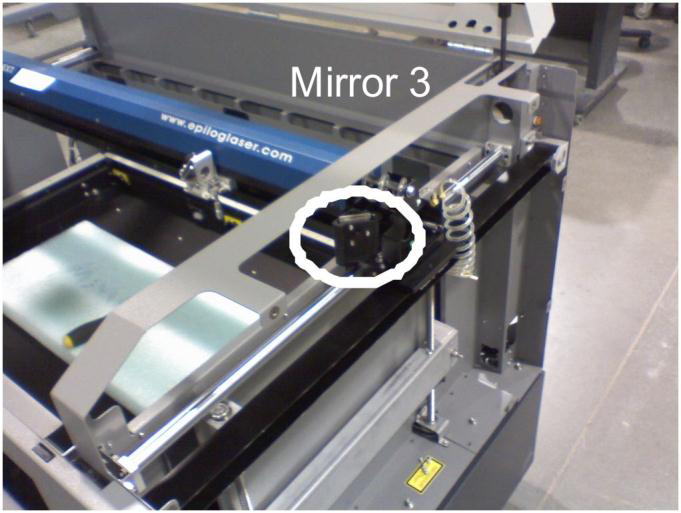
Adjust Mirror 3
Mirror 3 is on the right end of the rail, and its screws are reached from the right side of the engraver. Use them to center the red dot on the target.
Mirror 3 Screw Guide
- Top screw: clockwise moves the dot up the target; counterclockwise moves it down the target.
- Lower left screw: clockwise moves the dot to the lower left; counterclockwise moves it to the upper right.
- Lower right screw: clockwise moves the dot to the lower right; counterclockwise moves it to the upper left.
Check Position 4
Move the lens carriage to the front left corner of the table (position 4) and check the red dot. If it is not within the first circle of the target, check that the engraver is level.
Split the Difference
If the dot is within the first circle, use mirror 3 to move it halfway toward the center. This shares the error between positions 3 and 4: instead of position 3 dead on and position 4 off by 1/8", both are off by about 1/16".
Check All Four Corners
Check all four corners again. Positions 1 and 2 should be centered and positions 3 and 4 very close. If any corner is off, start over at position 1.
Finishing Up
Test Burn Each Corner
Make a quick burn mark at each of the four corners. Each burn should land on the red dot. If not, repeat the red dot alignment and then the mirror alignment.
Lock the Adjustment Screws
Put a small amount of glue (two-part epoxy works best, or any glue that sticks to metal) on every screw you adjusted, including the red dot screws, so they cannot move on their own. Do not use too much; you may need to break them free later.
Check the Beam Through the Lens
Remove the target, turn on the red dot and check that it passes through the center of the lens. If it does not, a perpendicular alignment may be needed (see Perpendicular Alignment – Legend 36EXT).
Replace the Panels and Test
Replace all the panels and run a test job. The engraving should come out correctly with an even burn across the table. If not, contact Epilog Technical Support.