
This guide covers removing and replacing the top door on the Fusion Edge 24. The control panel and right top cover are removed to reach the right hinge. All directions are given as if you are standing at the front of the engraver.
Parts Required
- Replacement Top Door
Tools Required
- 5/32" Allen Wrench
- 5/16" Nut Driver
- Phillips Screwdriver
Safety First: Ensure the engraver is completely powered off and the power cord is disconnected before removing any panels or touching internal components.
Pinch Points: The top door, hinges and gas shocks are pinch points. Keep your hands clear while the door moves, and support the door whenever the gas shocks are disconnected.
Top Door Removal
Turn Off Engraver
Turn off the engraver.
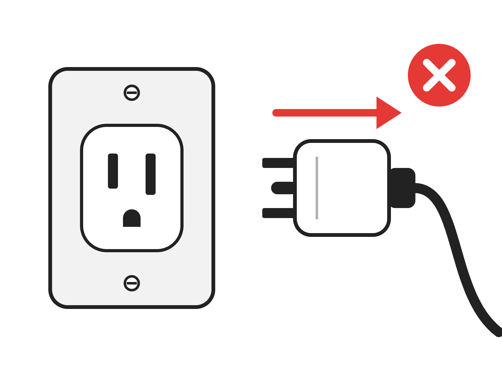
Disconnect from Power
Unplug the engraver from its power source.
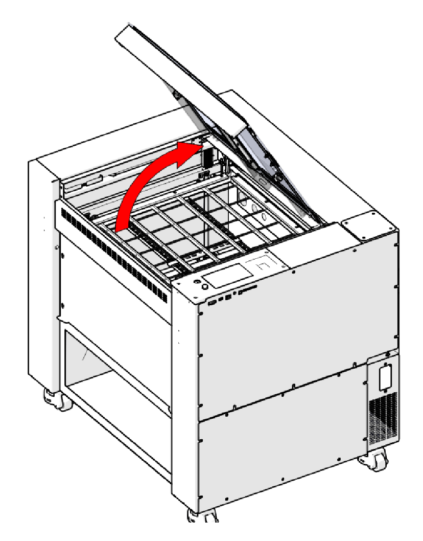
Open the Top Door
Open the top door.
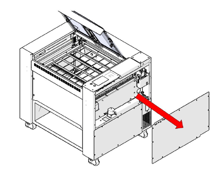
Remove Right Panel
Loosen the 5/32" cam locks and remove the right panel.
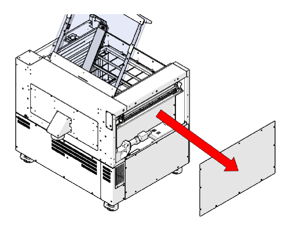
Remove Left Panel
Loosen the 5/32" cam locks and remove the left panel.
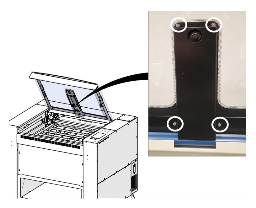
Remove the Lid Camera Mount
Remove the four 5/16" nuts (circled) that hold the lid camera mount on the inside of the top door.
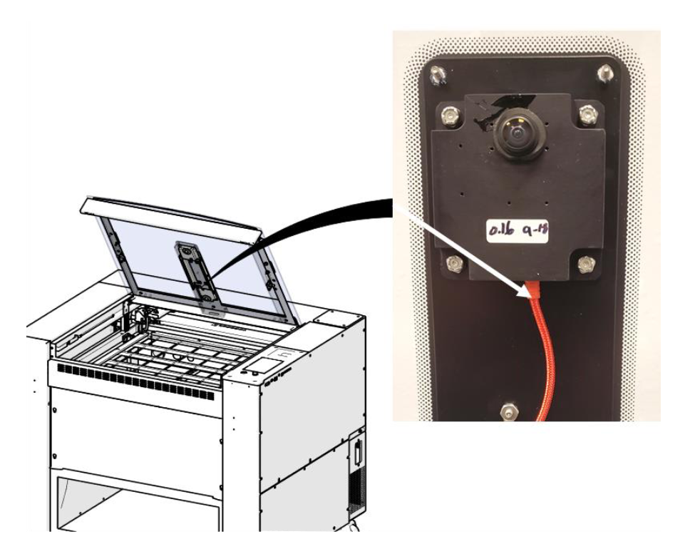
Disconnect the Camera Cable
Disconnect the USB cable from the lid camera (white arrow).
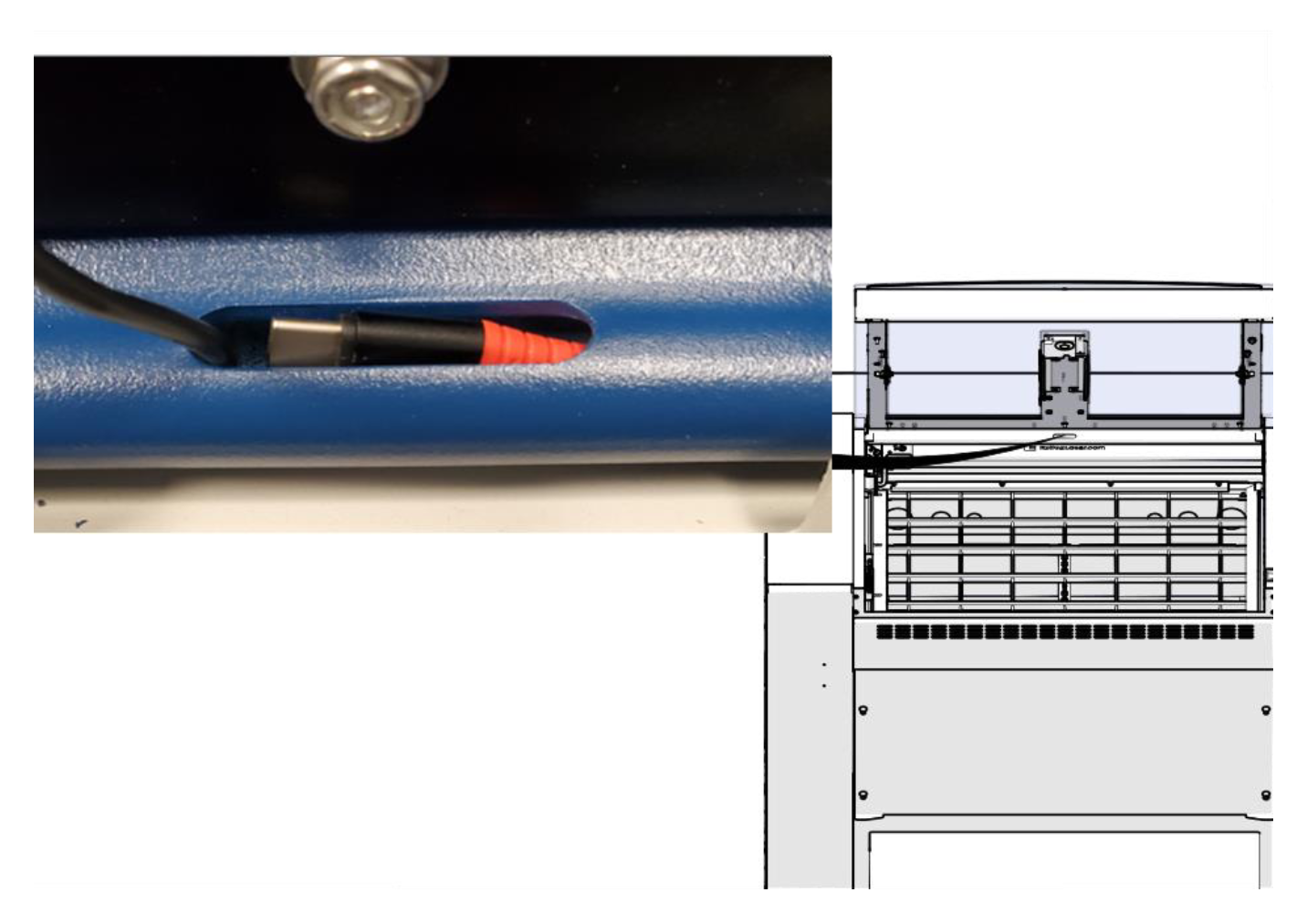
Push the Cable Into the Slot
Push the camera USB cable down into the slot in the frame so it stays with the engraver when the door is removed.
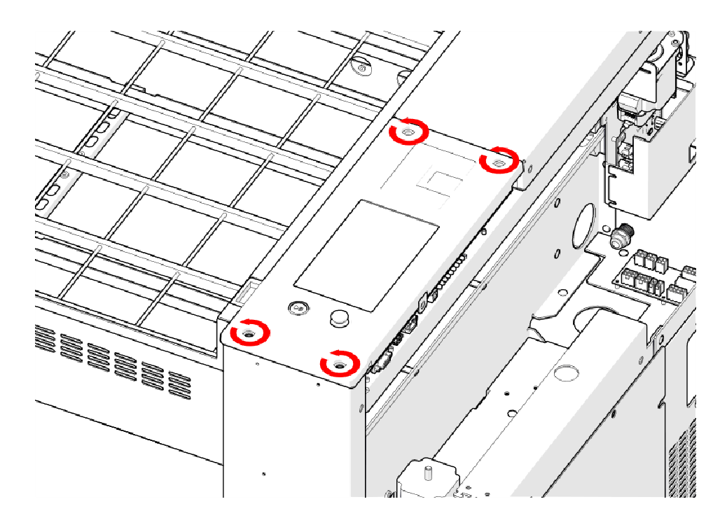
Remove Control Panel Screws
Remove the four 5/32" screws that secure the control panel at the front right of the engraver (circled in red).
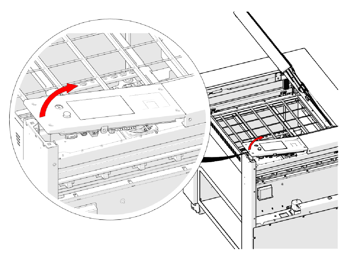
Raise the Control Panel
Lift the front edge of the control panel.
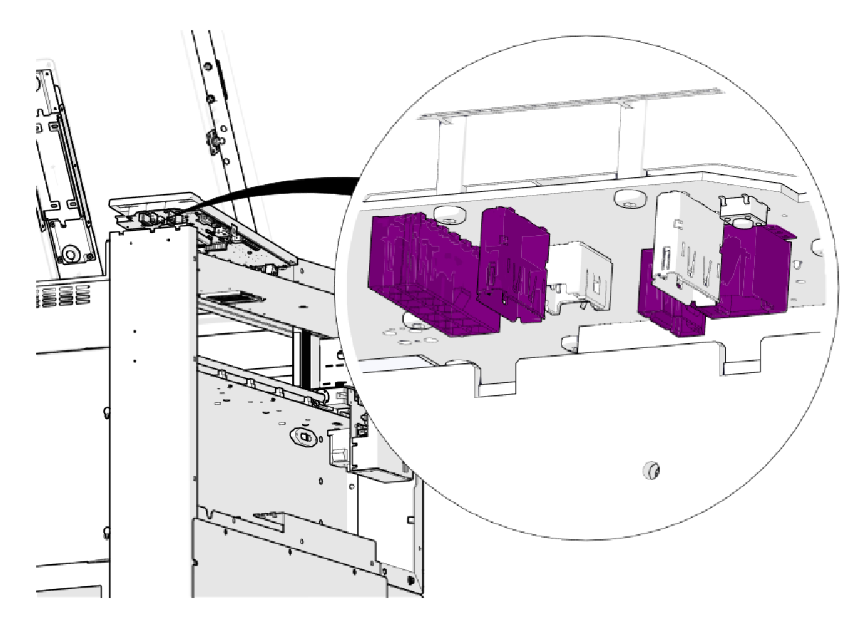
Disconnect Front Harnesses
Disconnect the harnesses at the front of the control panel (highlighted in purple).
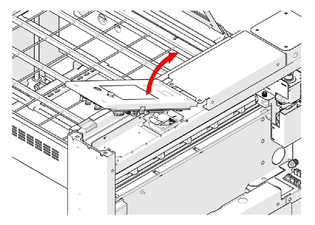
Raise It Further
Lift the control panel further.
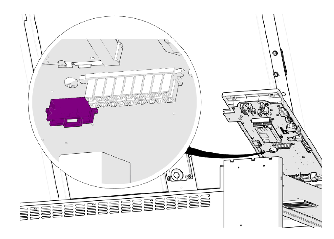
Disconnect the Ribbon Cable
Disconnect the ribbon cable (highlighted in purple).
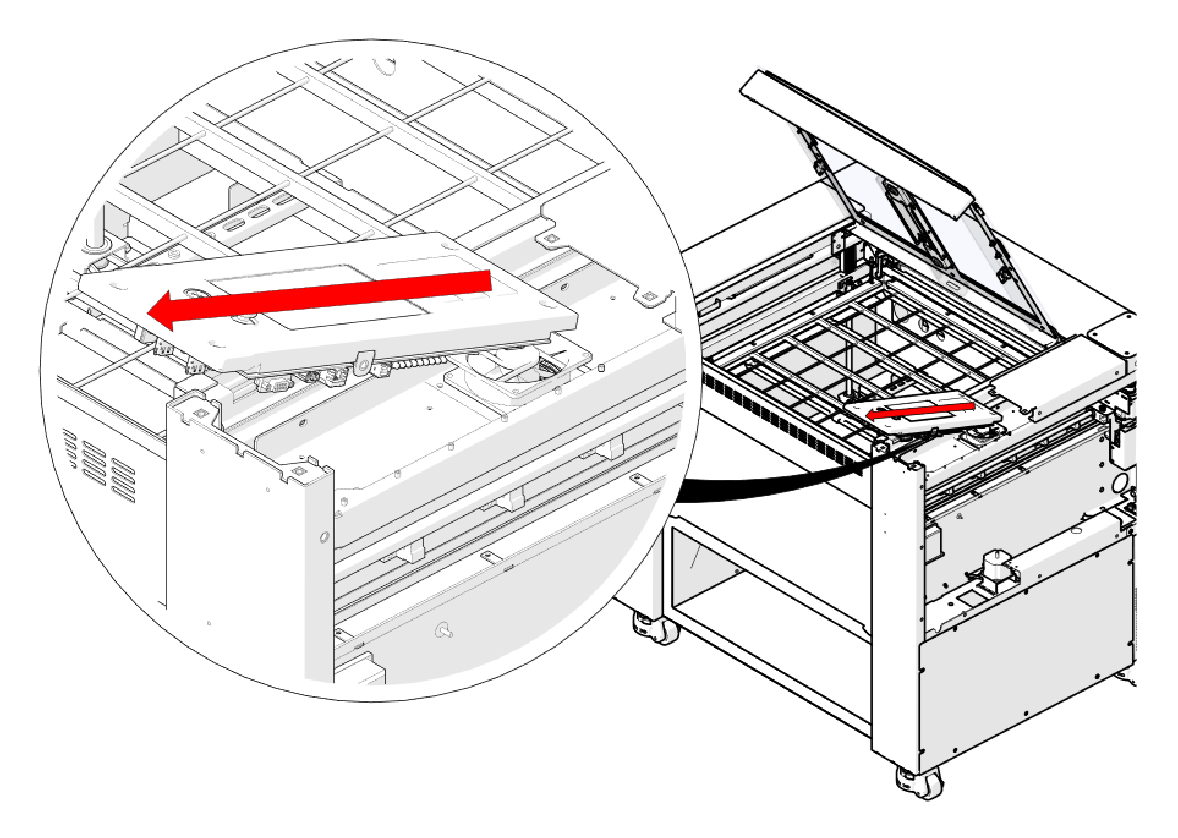
Move the Panel Forward
Lift the control panel and move it toward the front of the engraver.
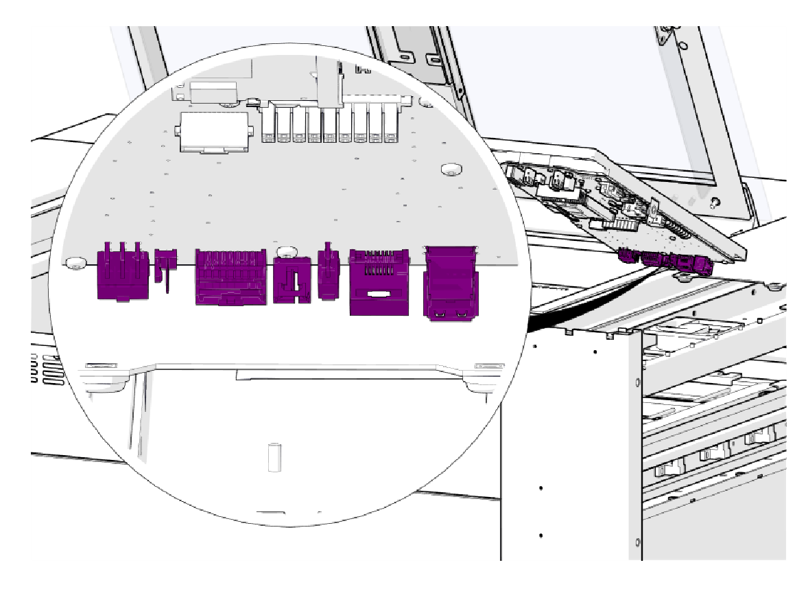
Disconnect Rear Harnesses
Disconnect the harnesses along the rear edge of the control panel board (highlighted in purple).
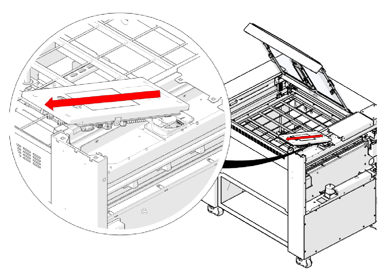
Remove the Control Panel
Slide the control panel forward and remove it from the engraver.
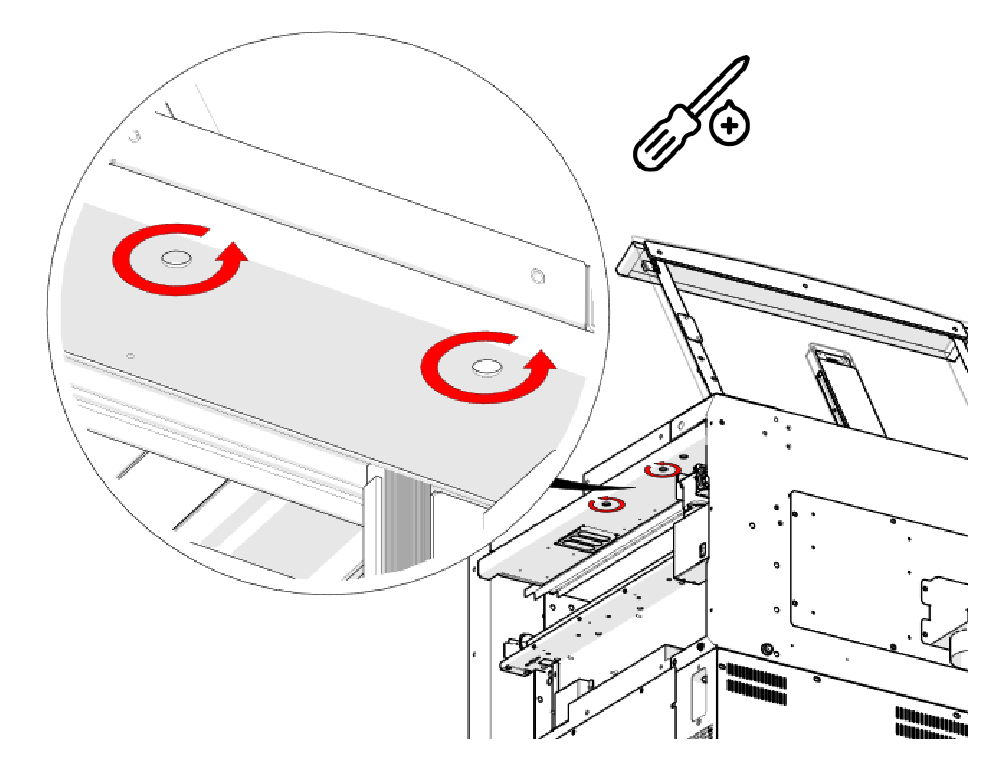
Remove Top Cover Screws
Remove the two Phillips screws under the control panel area (circled in red).
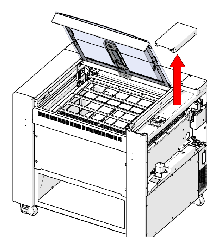
Remove the Right Top Cover
Lift off the right top cover.
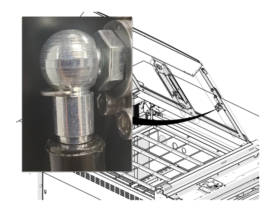
Locate the Gas Shock Ends
Locate the upper end of the right and left gas shocks, where they attach to ball studs on the top door.
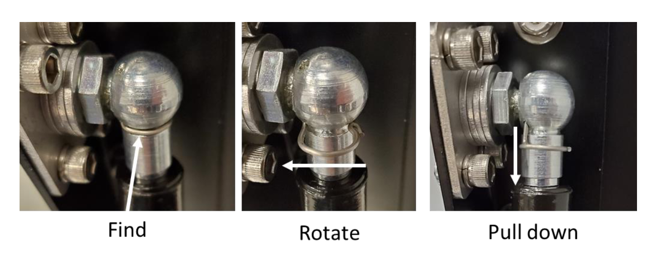
Release the Shock Clips
On both the left and right gas shocks, find the wire retaining clip, rotate it off the ball stud and pull it down.
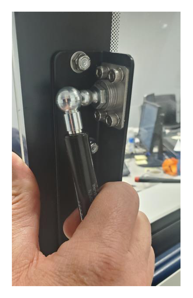
Disconnect the Gas Shocks
Support the door and pull the upper end of each gas shock off its ball stud.
Important: Pinch point. Keep your hands clear of the hinges and gas shocks while the door moves.
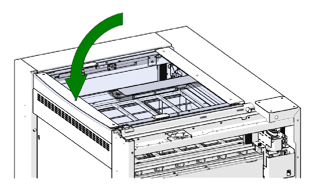
Close the Door Carefully
Carefully lower the top door. Without the gas shocks it is not supported.
Important: Pinch point. Keep your hands clear of the hinges and gas shocks while the door moves.
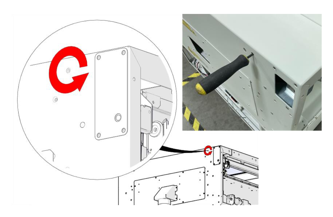
Loosen the Right Hinge Screw
From the right side, use a 5/32" Allen wrench through the access hole to loosen the hinge pin set screw (circled in red).
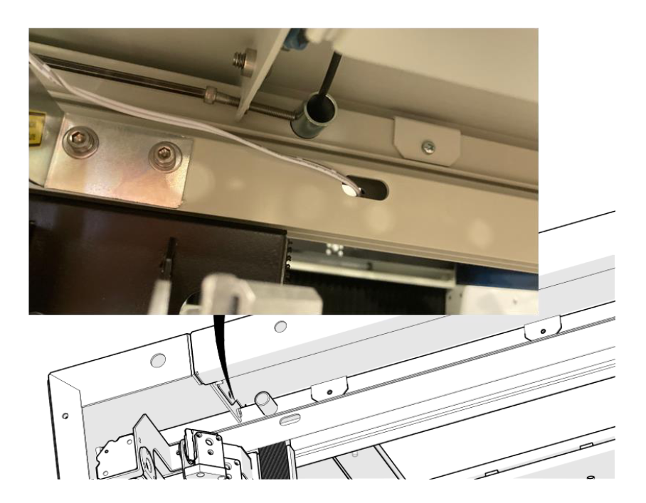
Find the Ground Wire
Locate the door ground wire at the rear of the door.
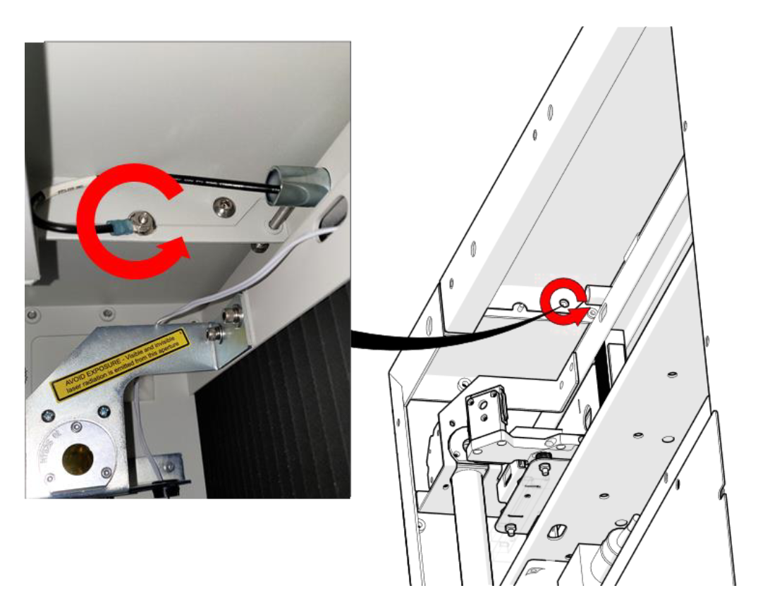
Disconnect the Ground Wire
Remove the screw that holds the door ground wire and disconnect the wire.
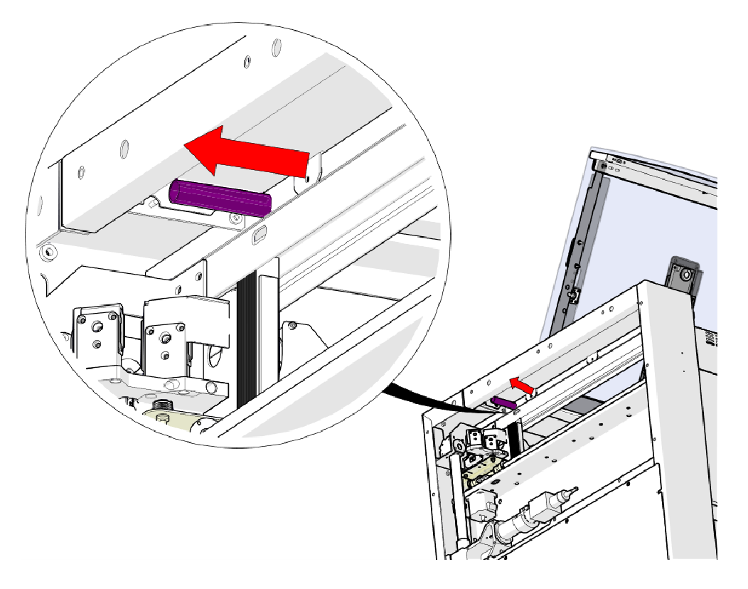
Clear the Right Hinge
Slide the right hinge pin (highlighted in purple) toward the center so it clears the door.
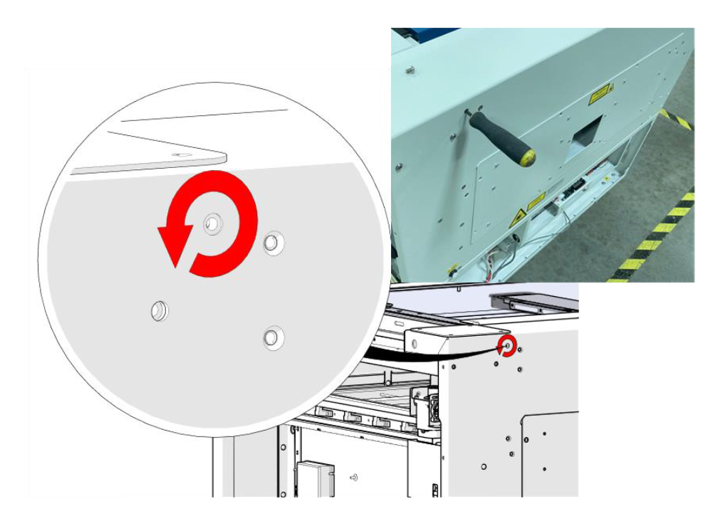
Loosen the Left Hinge Screw
From the left side, use a 5/32" Allen wrench through the access hole to loosen the other hinge pin set screw.
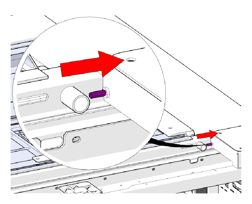
Check the Left Hinge Pin
Check the left hinge pin (highlighted in purple) and the direction it slides out (red arrow).
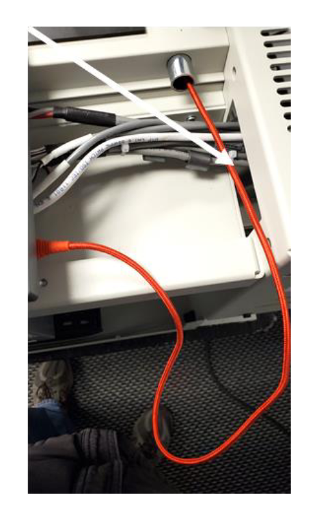
Free the Orange Cable
Free the orange cable shown so it does not catch when the door is lifted out.
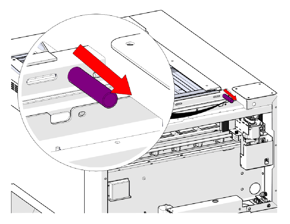
Clear the Left Hinge
Slide the left hinge pin outward so it clears the door.
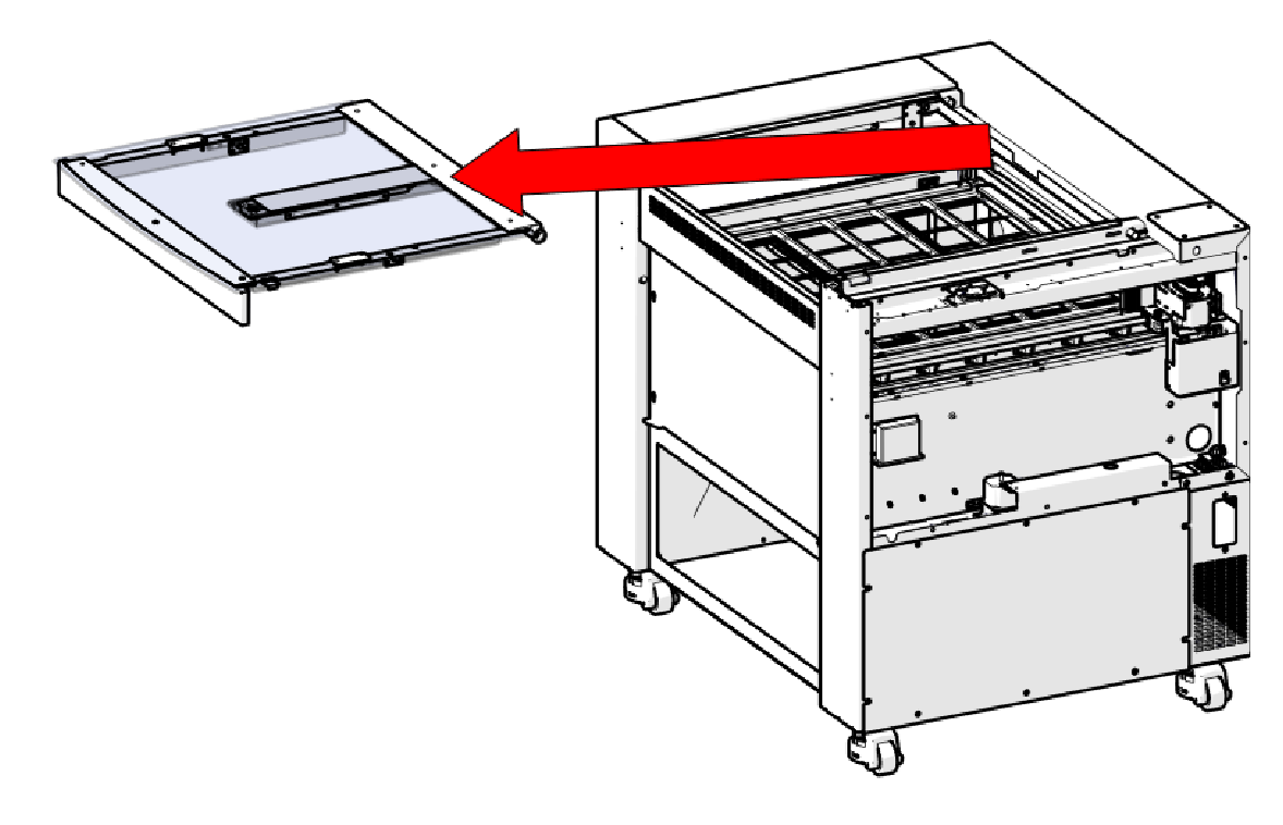
Remove the Top Door
Lift the top door off the engraver.
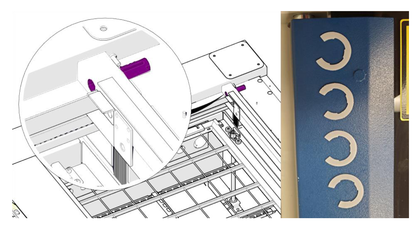
Collect the Shims
Collect the C-shaped shims from each hinge (right and left) and keep them with the hinge pins. They go back on the new door.
Top Door Installation
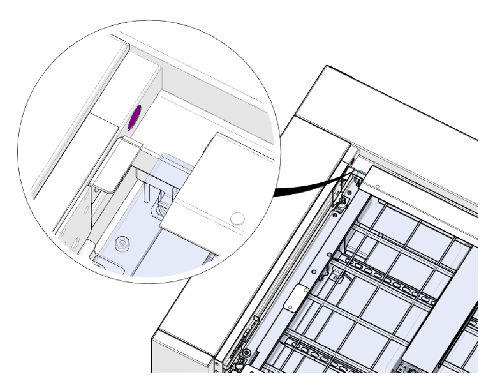
Position the Top Door
Set the new top door in place over the hinges.
Important: Pinch point. Keep your hands clear of the hinges and gas shocks while the door moves.
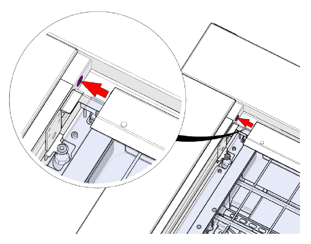
Pass the Ground Wire
Pass the door ground wire through the opening shown (red arrow).
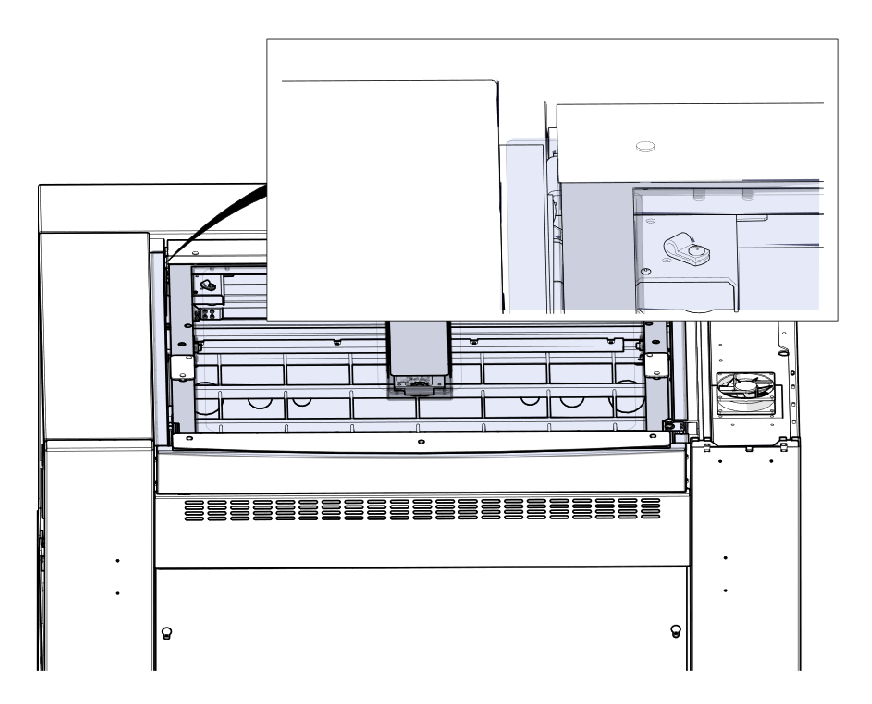
Line Up the Right Hinge
Line up the right door hinge with the hinge bracket.
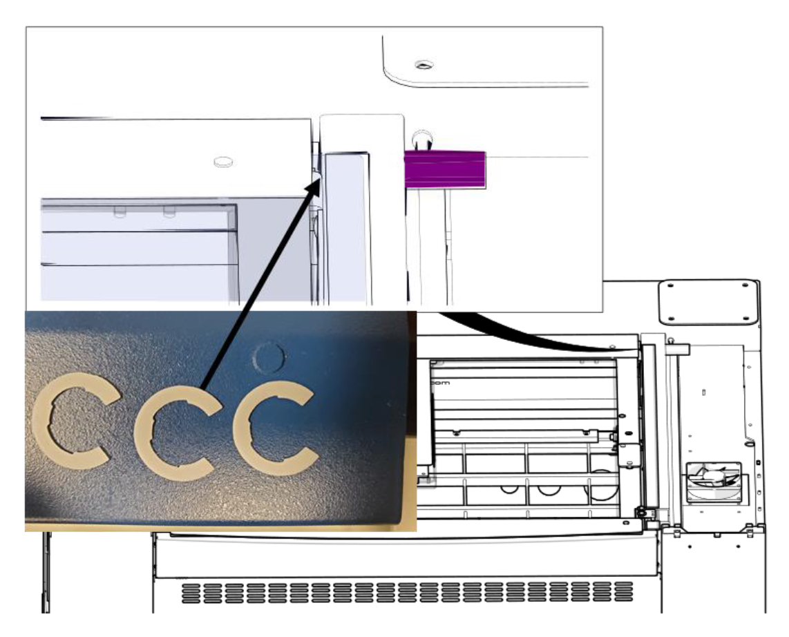
Install Right Shims
Install the C-shaped shims on the right hinge pin (highlighted in purple), using the same number you removed.
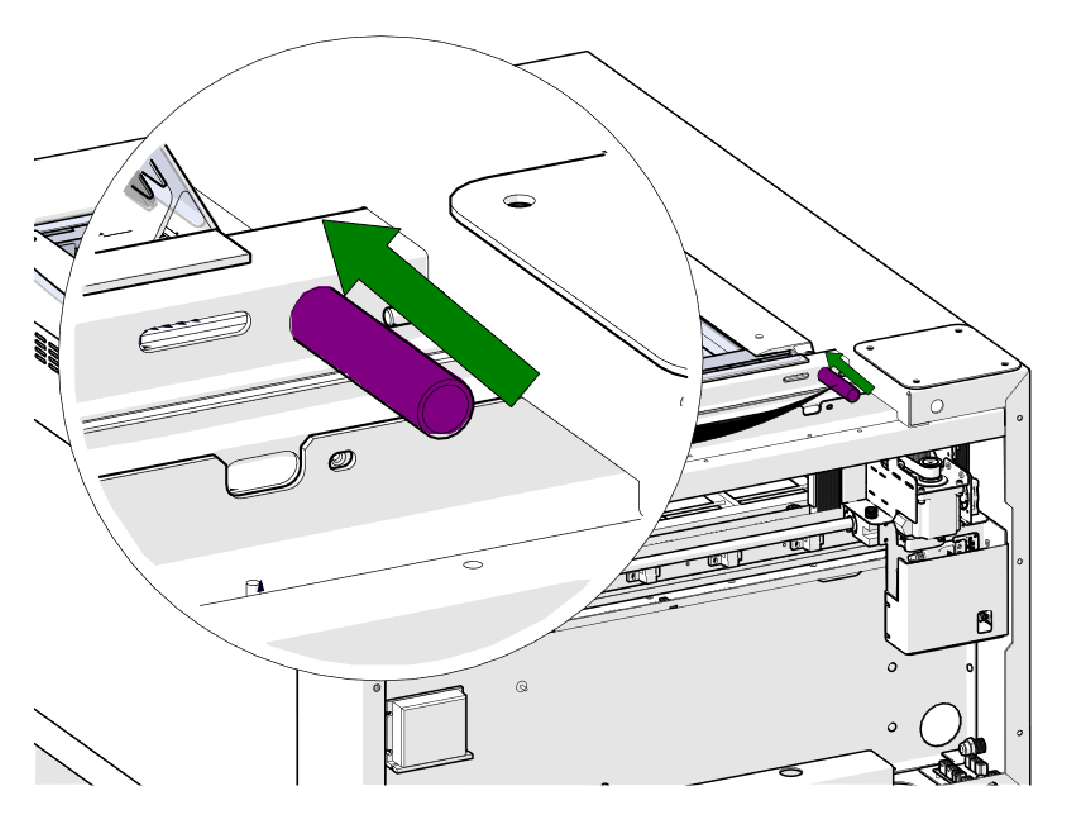
Install the Right Hinge Pin
Slide the right hinge pin back into the hinge (green arrow).
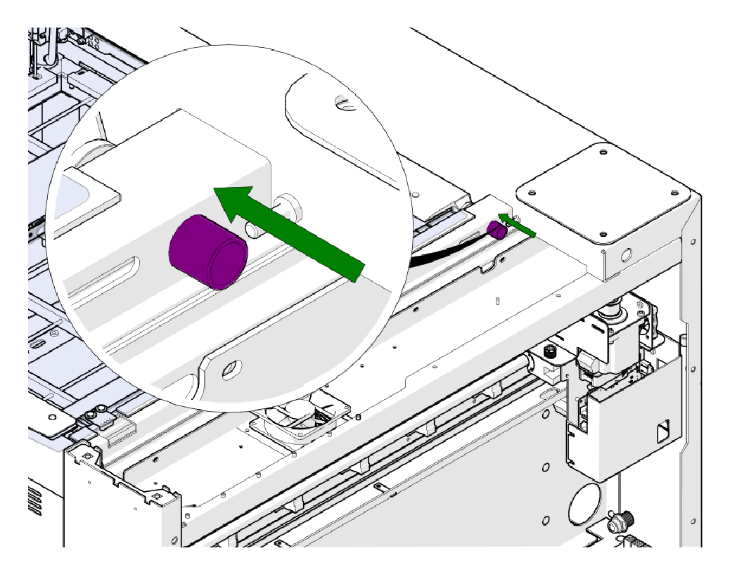
Check the Right Pin
Make sure the right hinge pin is fully seated.
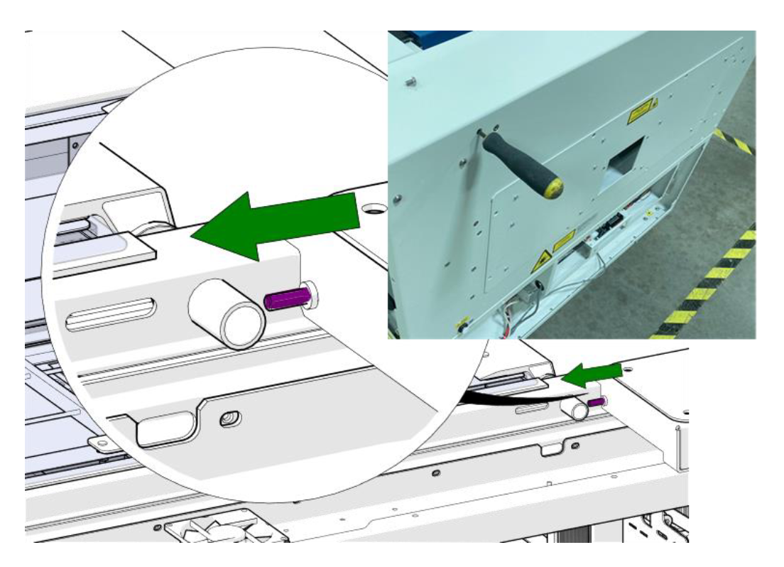
Tighten the Right Hinge Screw
Through the right side access hole, tighten the 5/32" hinge pin set screw.
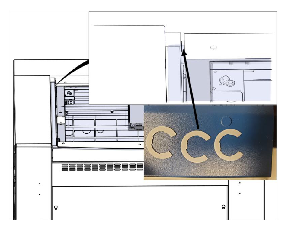
Install Left Shims
Install the C-shaped shims on the left hinge.
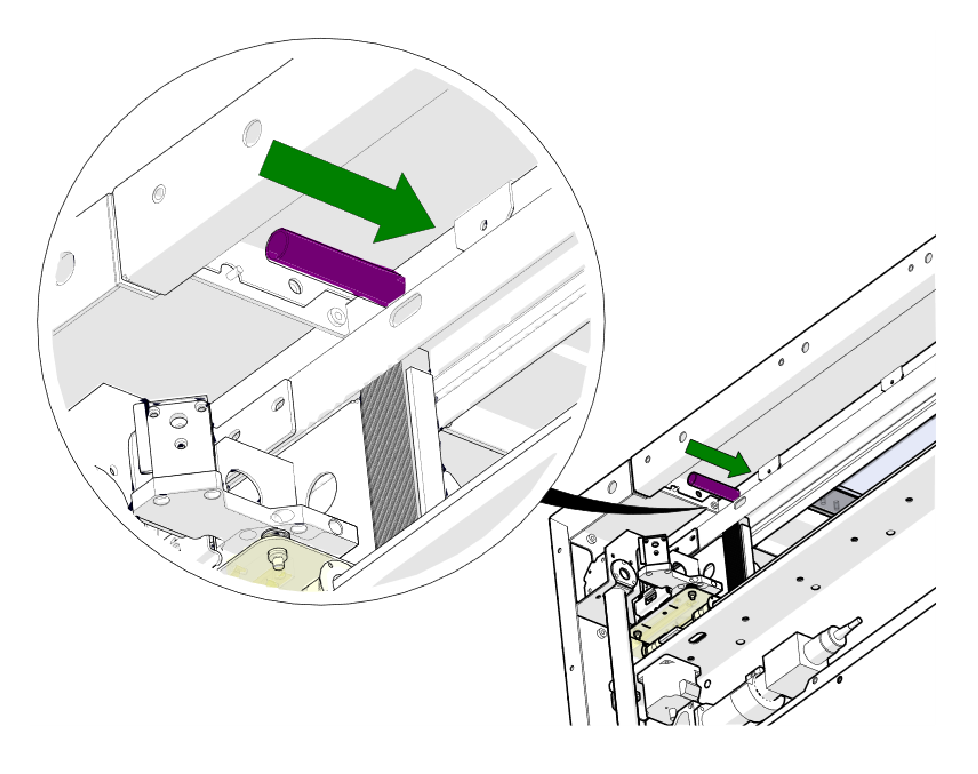
Install the Left Hinge Pin
Slide the left hinge pin back into the hinge (green arrow).
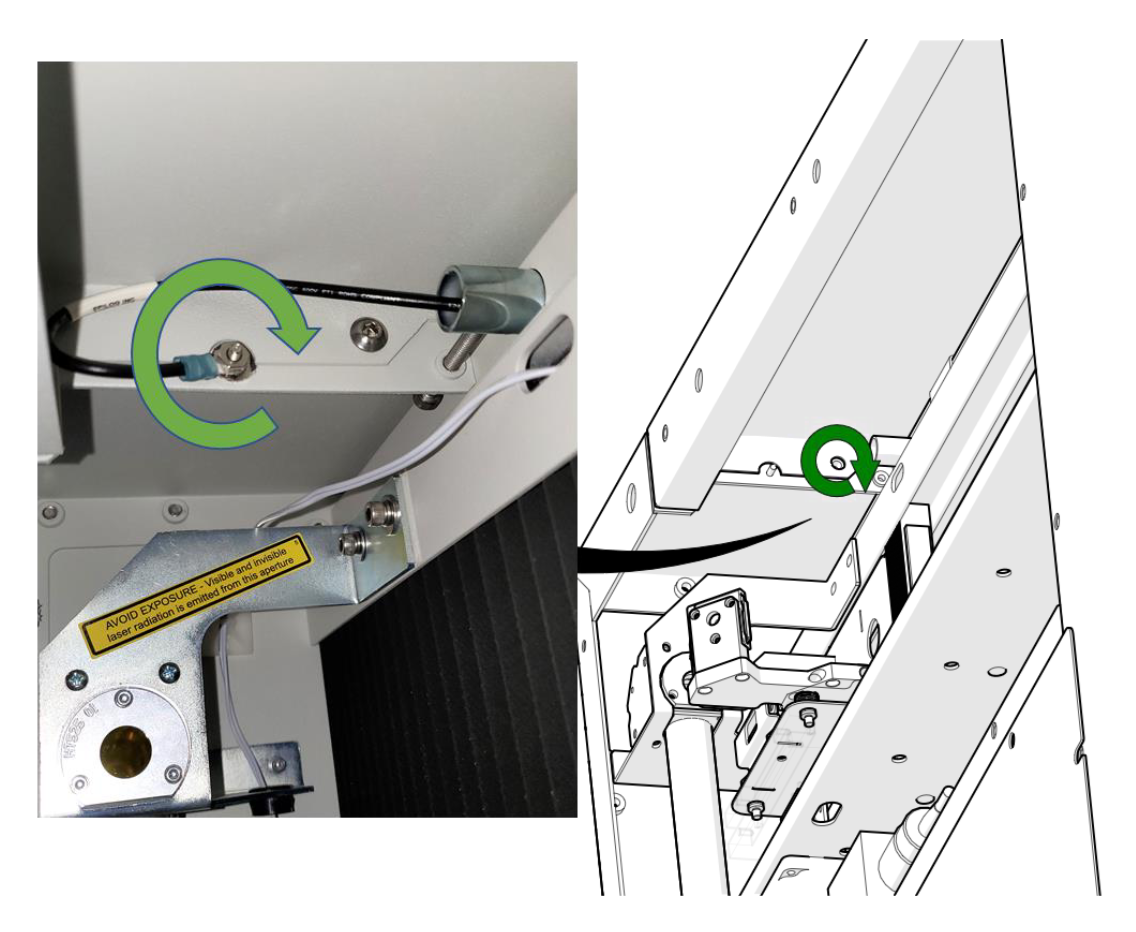
Connect the Ground Wire
Attach the door ground wire with its screw and tighten it.
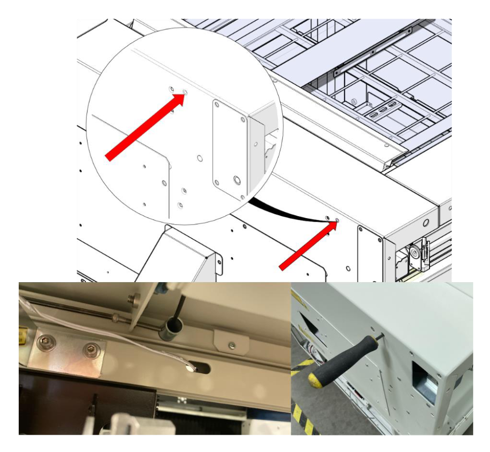
Tighten the Left Hinge Screw
Through the left side access hole, tighten the 5/32" hinge pin set screw.
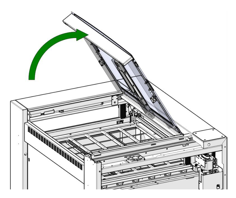
Open the Top Door
Carefully open the top door and hold it open.
Important: Pinch point. Keep your hands clear of the hinges and gas shocks while the door moves.
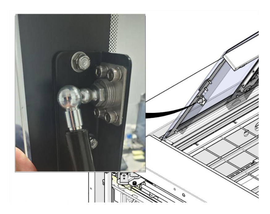
Connect the Gas Shocks
Press the upper end of the right and left gas shocks onto their ball studs.
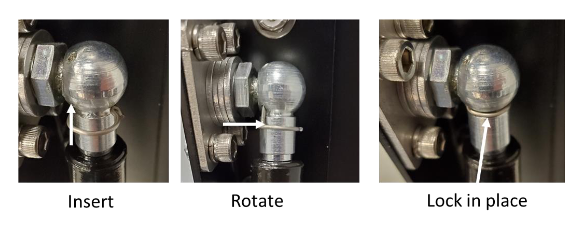
Install the Shock Clips
On each gas shock, insert the wire retaining clip, rotate it over the ball stud and lock it in place.
Route the Orange Cable
Route the orange cable back as shown.
Pull the Camera Cable Through
Pull the camera USB cable back out of the slot.
Connect the Camera Cable
Connect the USB cable to the lid camera.
Install the Lid Camera Mount
Install the lid camera mount on the new door with the four 5/16" nuts.
Install the Right Top Cover
Install the right top cover and tighten its two Phillips screws.
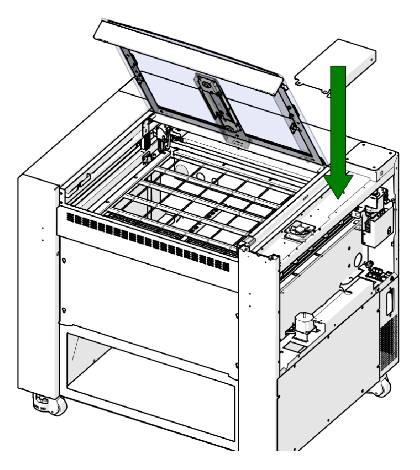
Place the Control Panel
Set the control panel back in the engraver and slide it toward the rear.
Connect Rear Harnesses
Connect the harnesses along the rear edge of the control panel board.
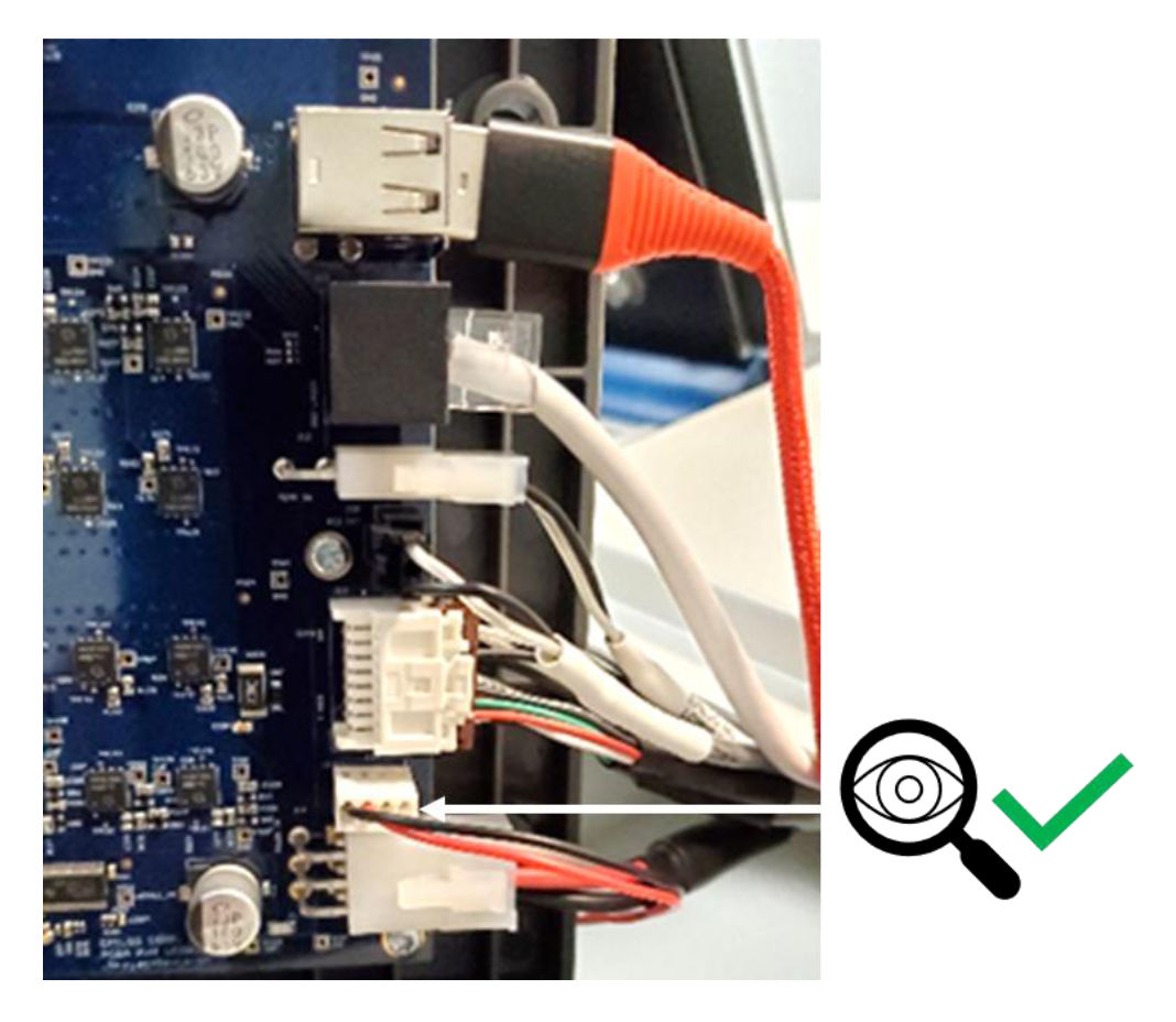
Check the Connectors
Check that each connector is fully seated (example shown).
Connect the Ribbon Cable
Connect the ribbon cable.
Connect Front Harnesses
Connect the harnesses at the front of the control panel.
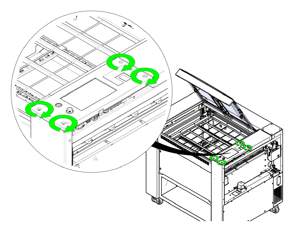
Install Control Panel Screws
Lower the control panel into place and install the four 5/32" screws: the two long screws at the rear and the two short screws at the front.
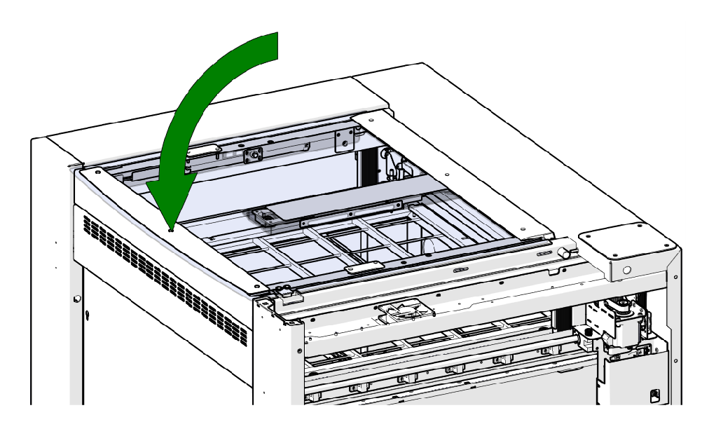
Close the Top Door
Close the top door.
Install Side Panels
Install the right and left panels.
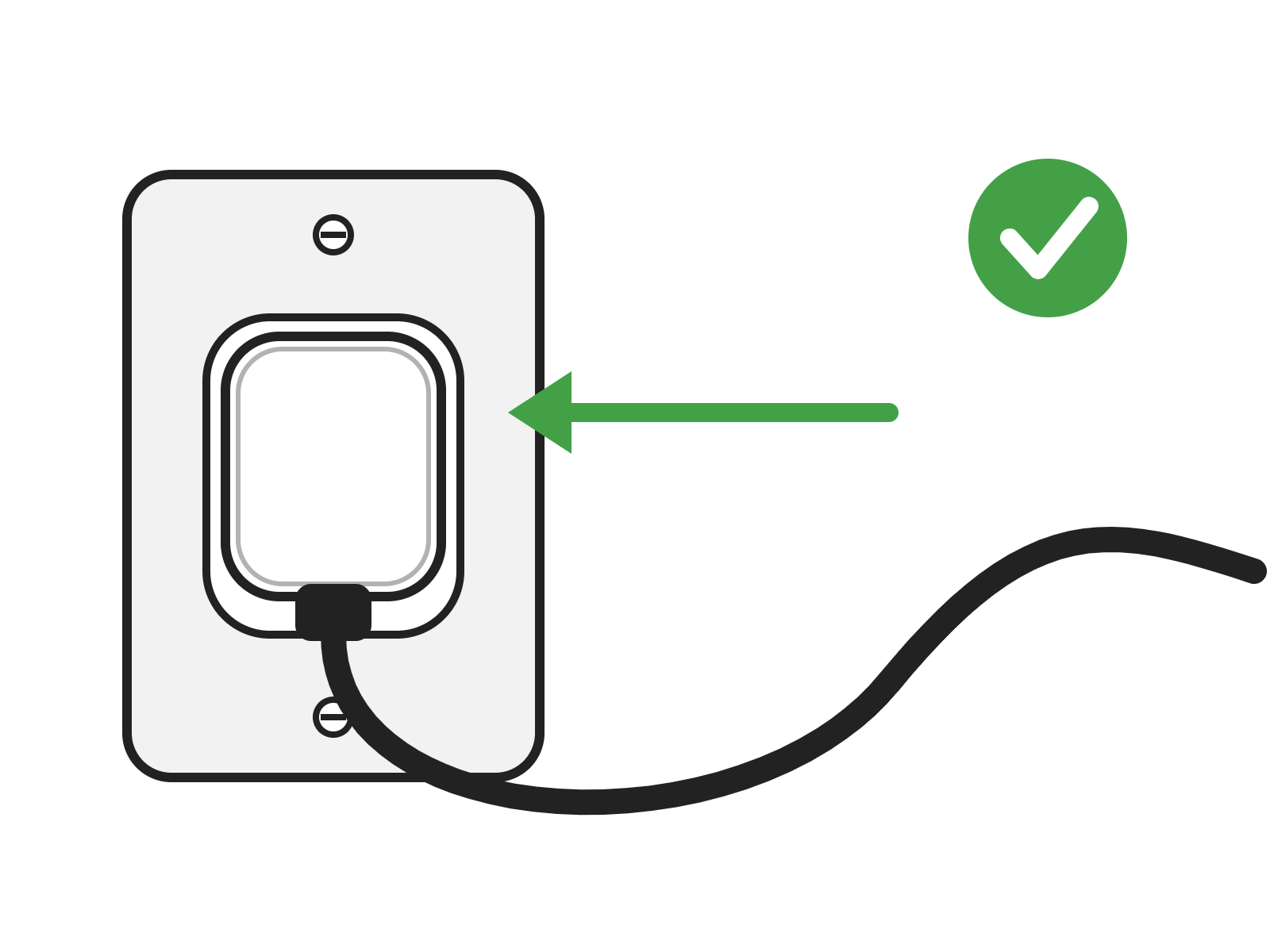
Power On
Reconnect the engraver to power and turn it on.
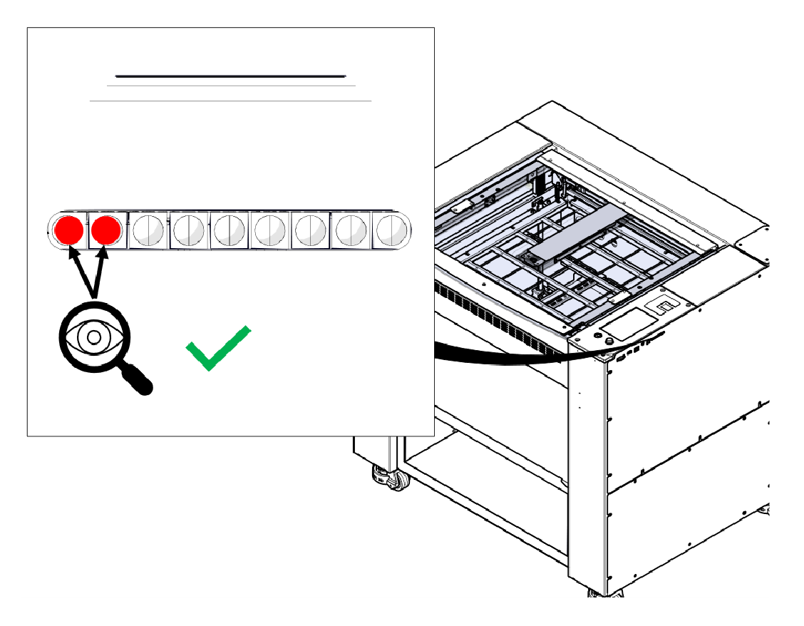
Check the Door Indicators
With the top door closed, check the status indicators on the display. The two indicators shown should look as they do here.