
This guide covers replacing a table lead screw on the Fusion Galvo G100. It shows the right-side lead screw; the left-side procedure is identical. The galvo platform is supported on the shipping brackets while the lead screw is out.
Parts Required
- LC0792 – Assy, Leadscrew, Table, 1/2OD
Tools Required
- T30 and T20 Torx Drivers
- 9/64″ Allen Wrench
- Pencil or Marker
Safety First: The engraver is powered on only to raise the galvo platform (Steps 7-16). Power it off and disconnect the power cord before continuing. This procedure requires laying the engraver on its back, so have a second person available to help.
Lead Screw Removal
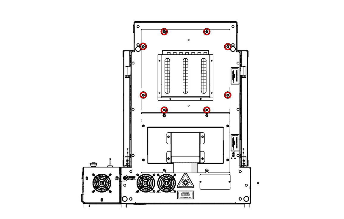
Remove Upper Rear Panel Screws
At the back of the engraver, loosen and remove the eight screws securing the upper rear panel (highlighted in red).
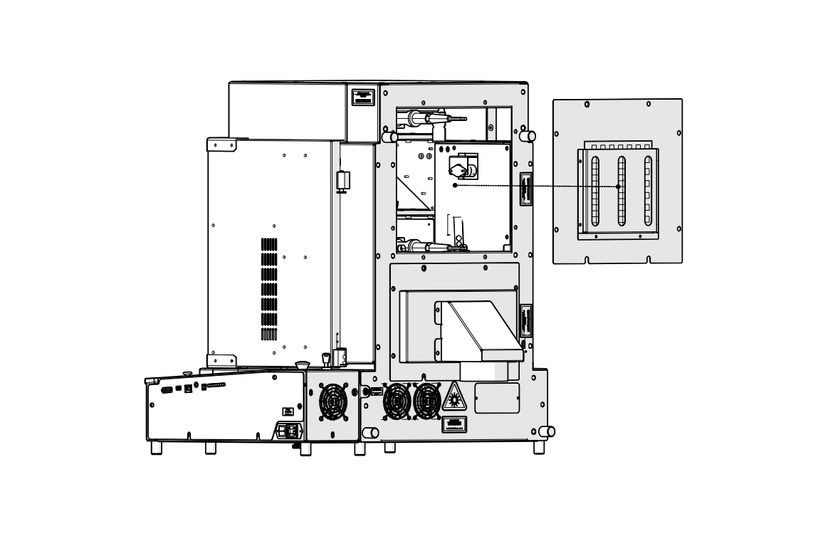
Remove Upper Rear Panel
Remove the upper rear panel.
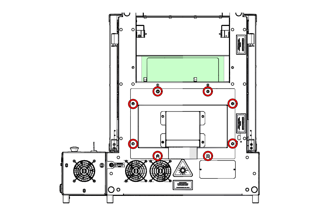
Remove Lower Rear Panel Screws
Loosen and remove the eight screws securing the lower rear panel (highlighted in red).
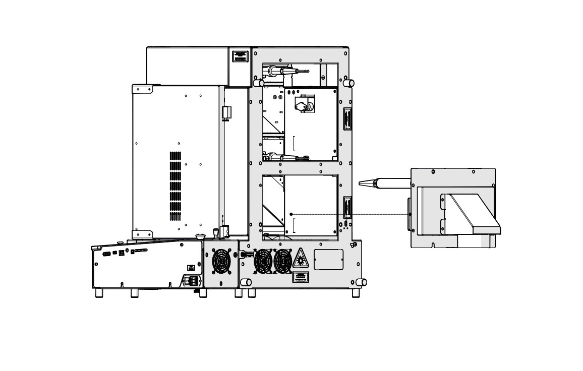
Remove Lower Rear Panel
Pull the lower rear panel and its exhaust duct straight back off the engraver.
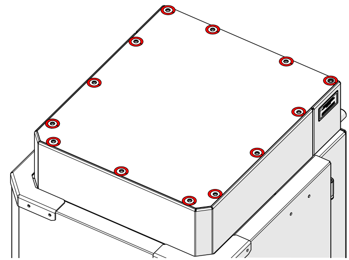
Remove Top Panel Screws
Loosen and remove the screws around the edge of the top panel (highlighted in red).
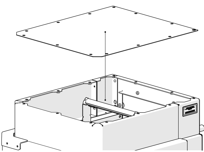
Remove Top Panel
Lift the top panel off the engraver and set it aside.
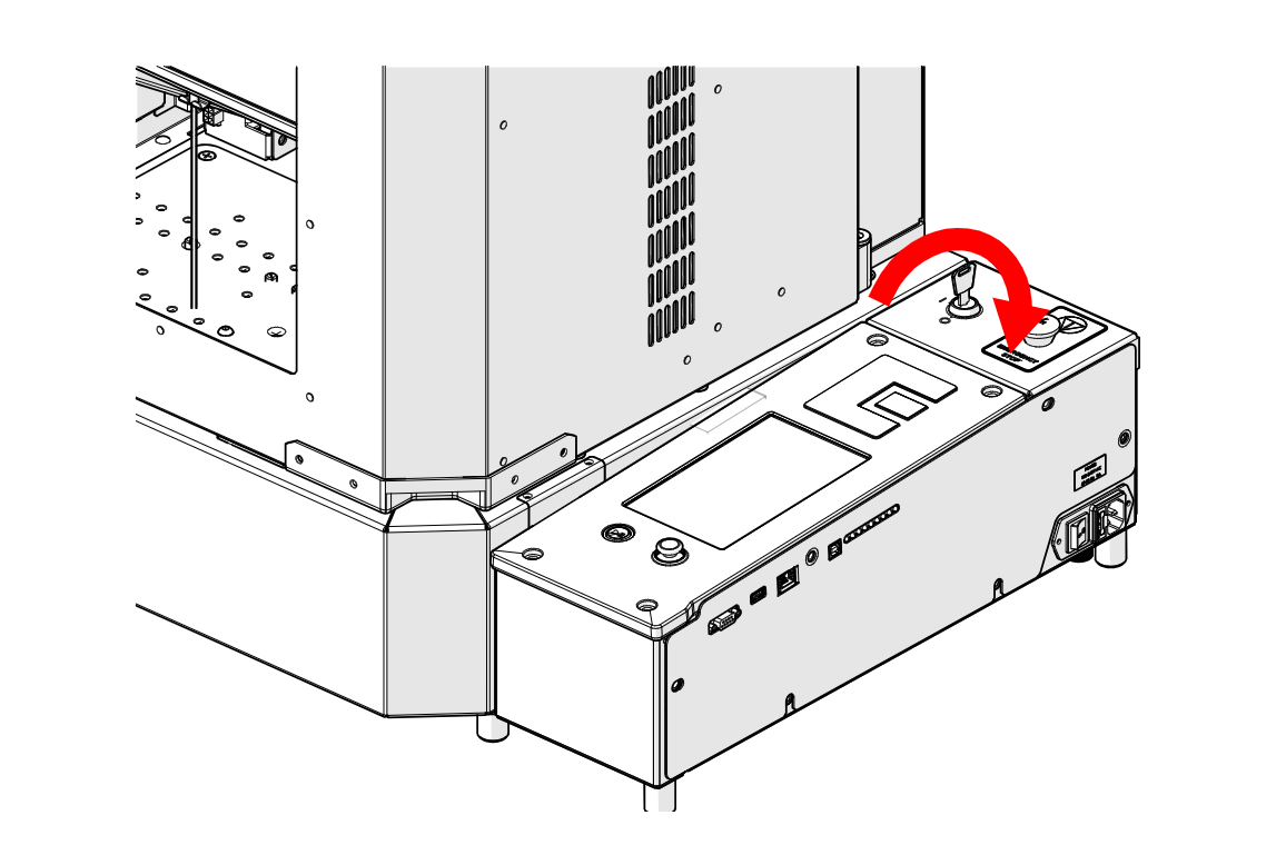
Turn On Engraver
Turn the key switch to power on the engraver.
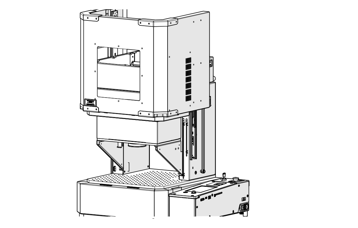
Open the Door
Open the engraver door.
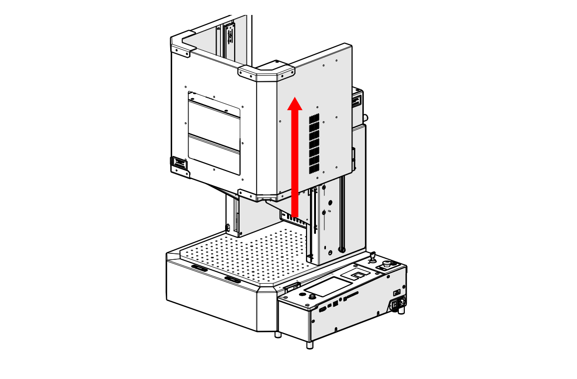
Raise Galvo Platform
Use the joystick to raise the galvo platform all the way to the top of the engraver.
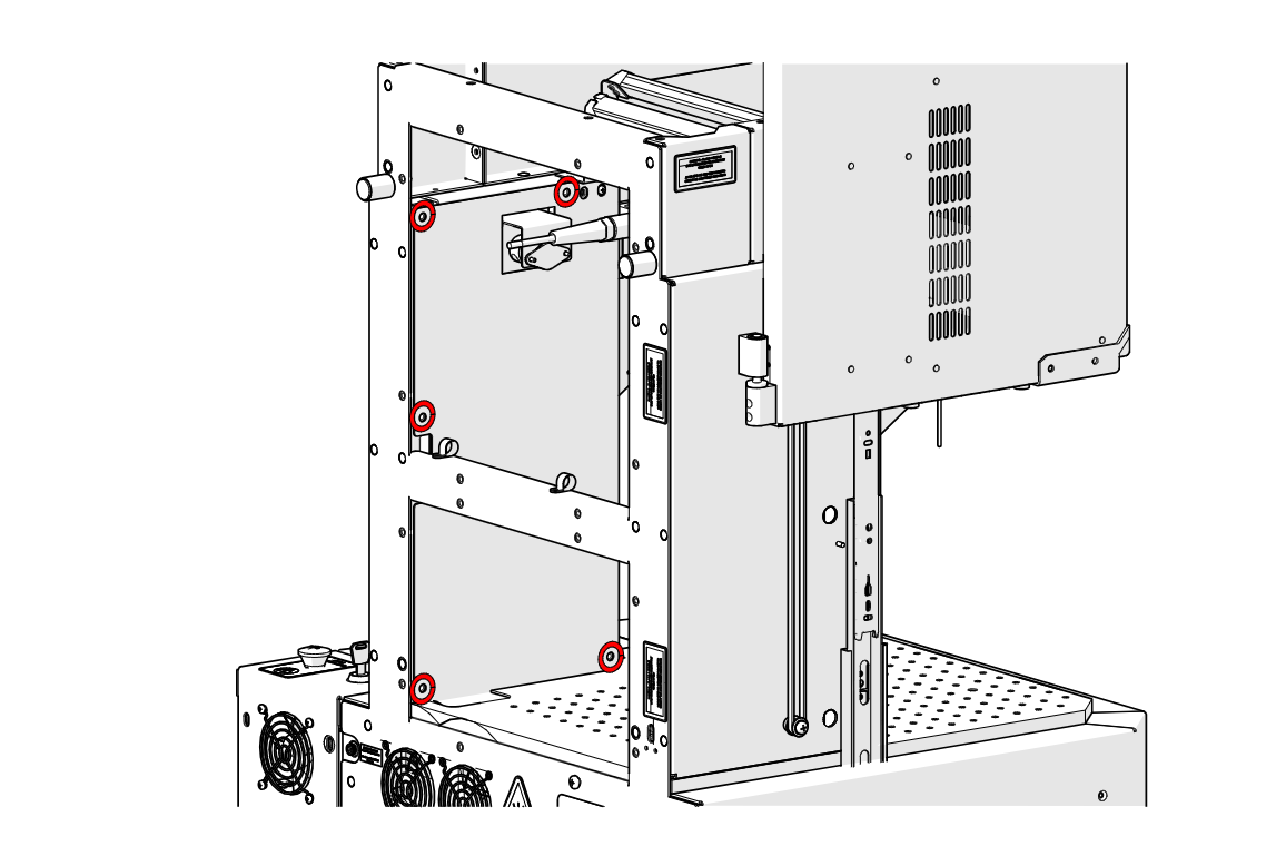
Remove Side Panel Screws
Loosen and remove the screws securing the side panel (highlighted in red).
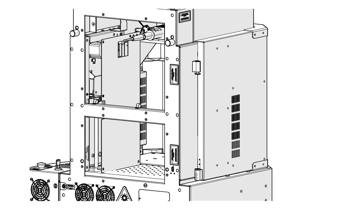
Remove Side Panel
Remove the side panel.
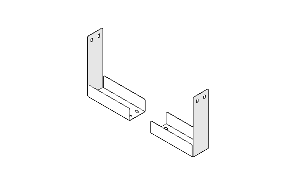
Locate Shipping Brackets
Locate the two shipping brackets that came with the engraver.
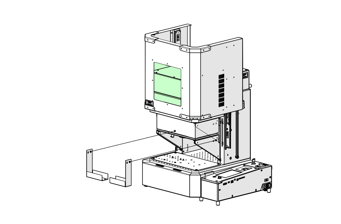
Install Shipping Brackets
Position the shipping brackets under the galvo platform.
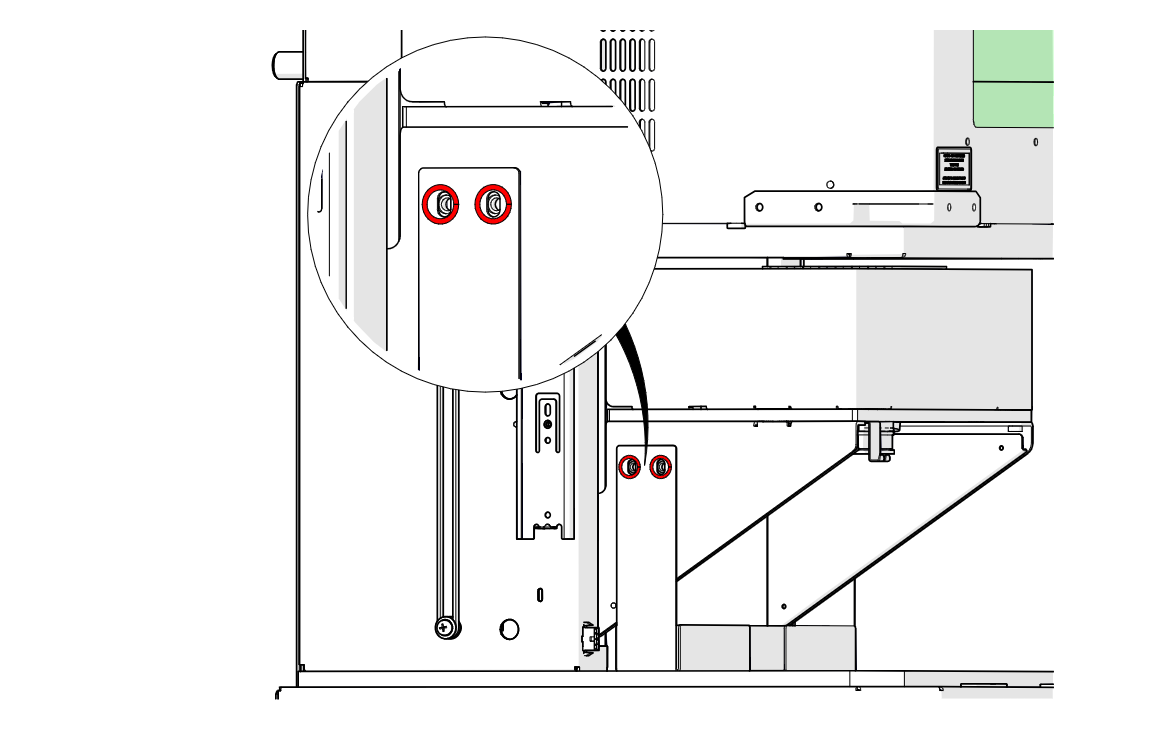
Secure First Bracket
Install and tighten the two screws on the first bracket (highlighted in red).
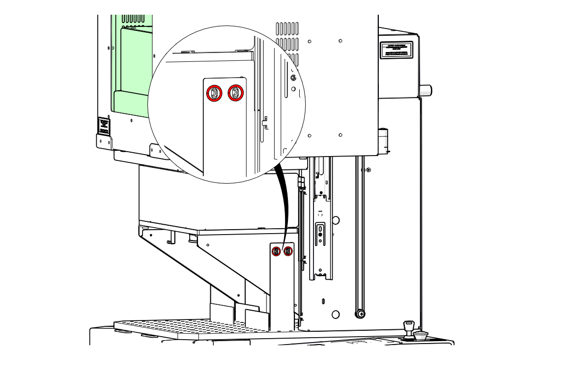
Secure Second Bracket
Install and tighten the two screws on the second bracket (highlighted in red).
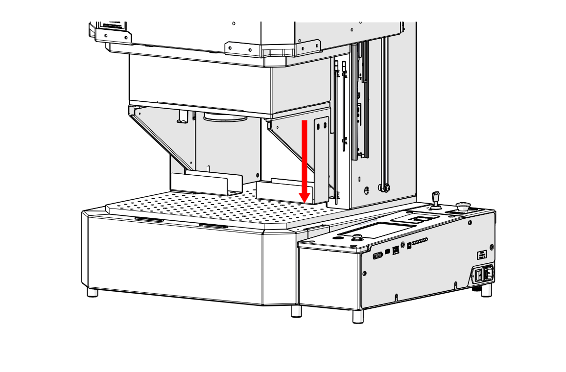
Lower Galvo Platform
Gently lower the galvo platform until the brackets rest on the table.
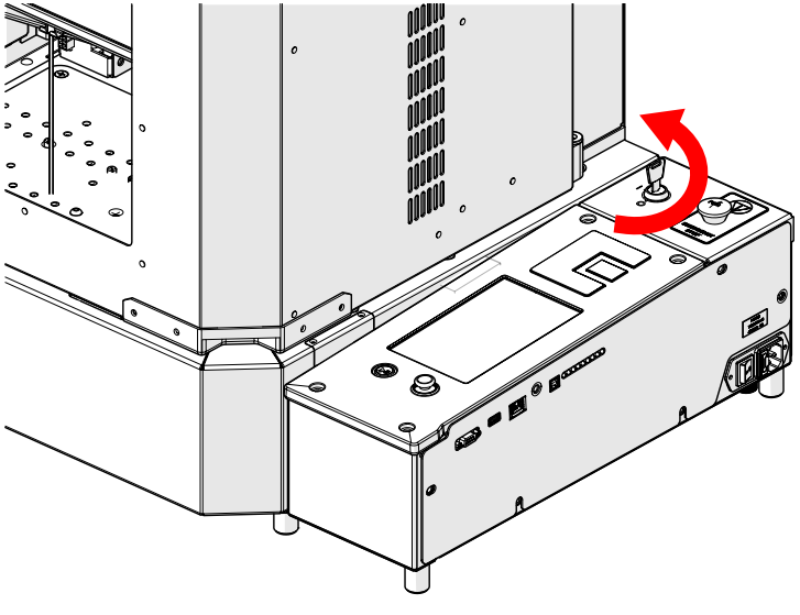
Turn Off Engraver
Turn the key switch to the off position to power down the engraver.
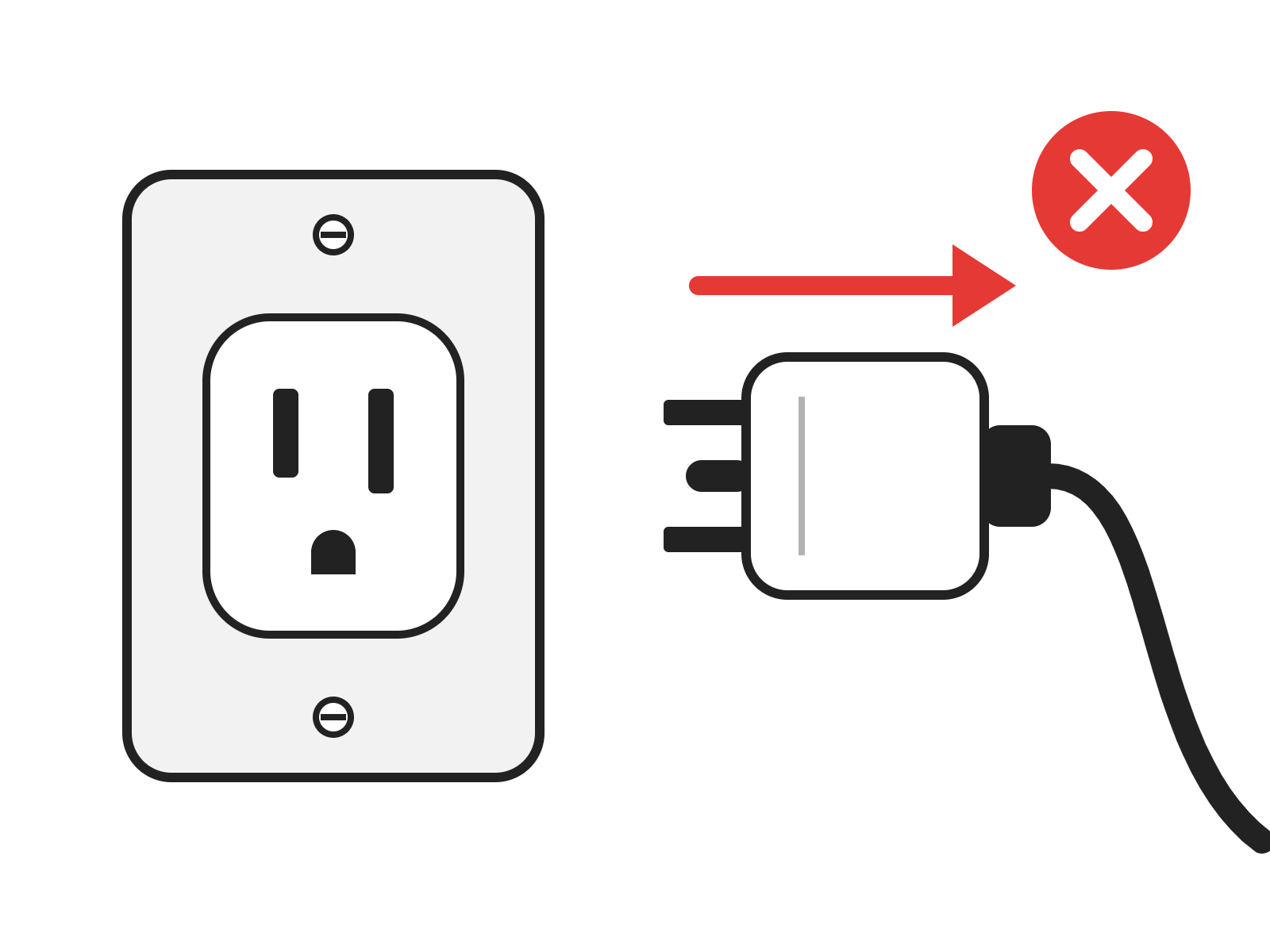
Disconnect from Power
Unplug the power cord from the engraver.
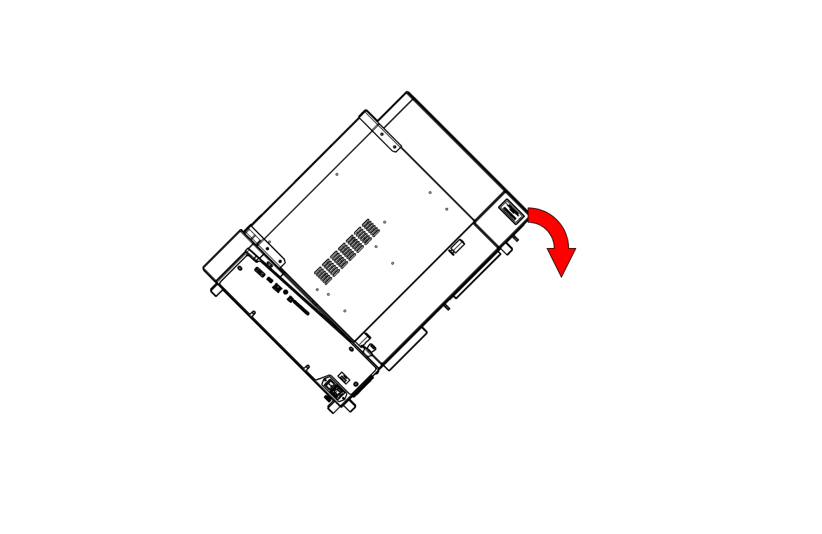
Tilt Engraver
Carefully tilt the engraver backward.
Note: The engraver is heavy. Use two people to tilt it.
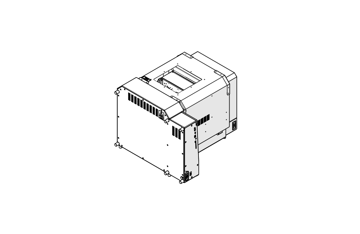
Lay Engraver on Its Back
Lower the engraver until it rests on its back, giving access to the bottom panel.
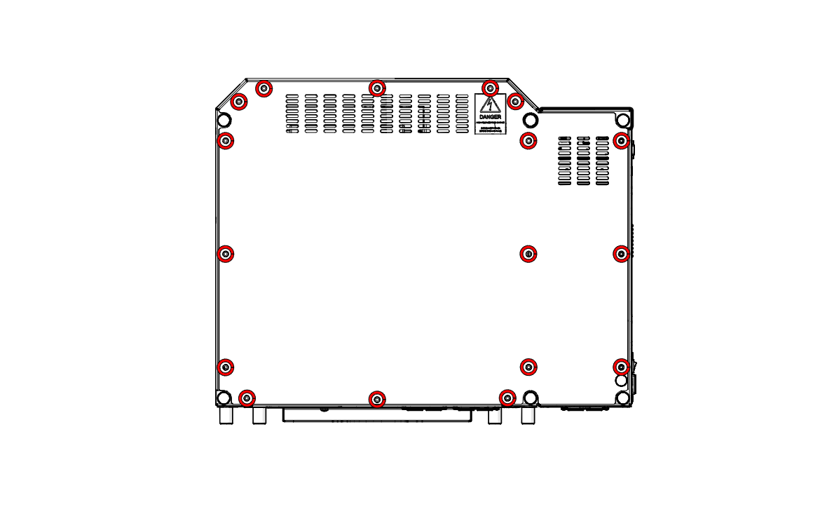
Remove Bottom Panel Screws
Loosen and remove the screws around the bottom panel (highlighted in red).
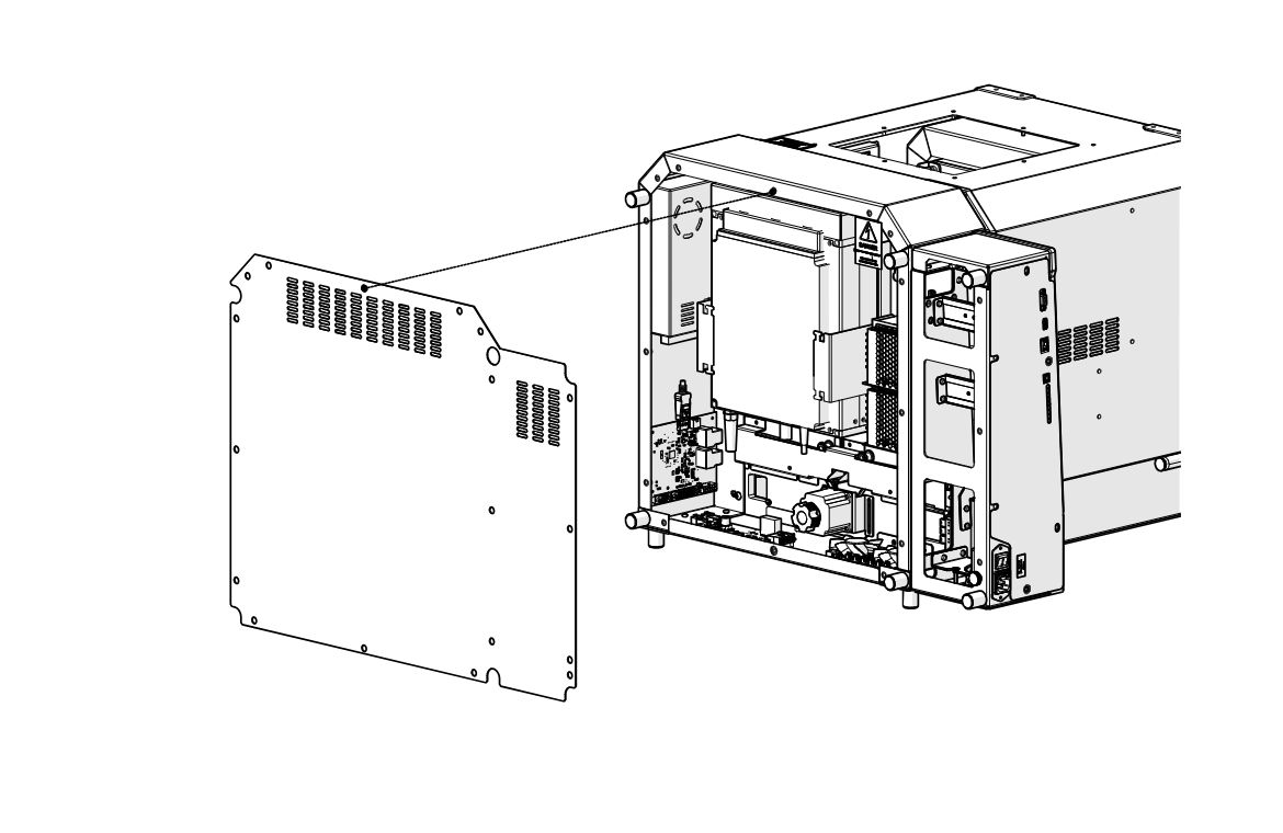
Remove Bottom Panel
Lift the bottom panel off the engraver and set it aside.
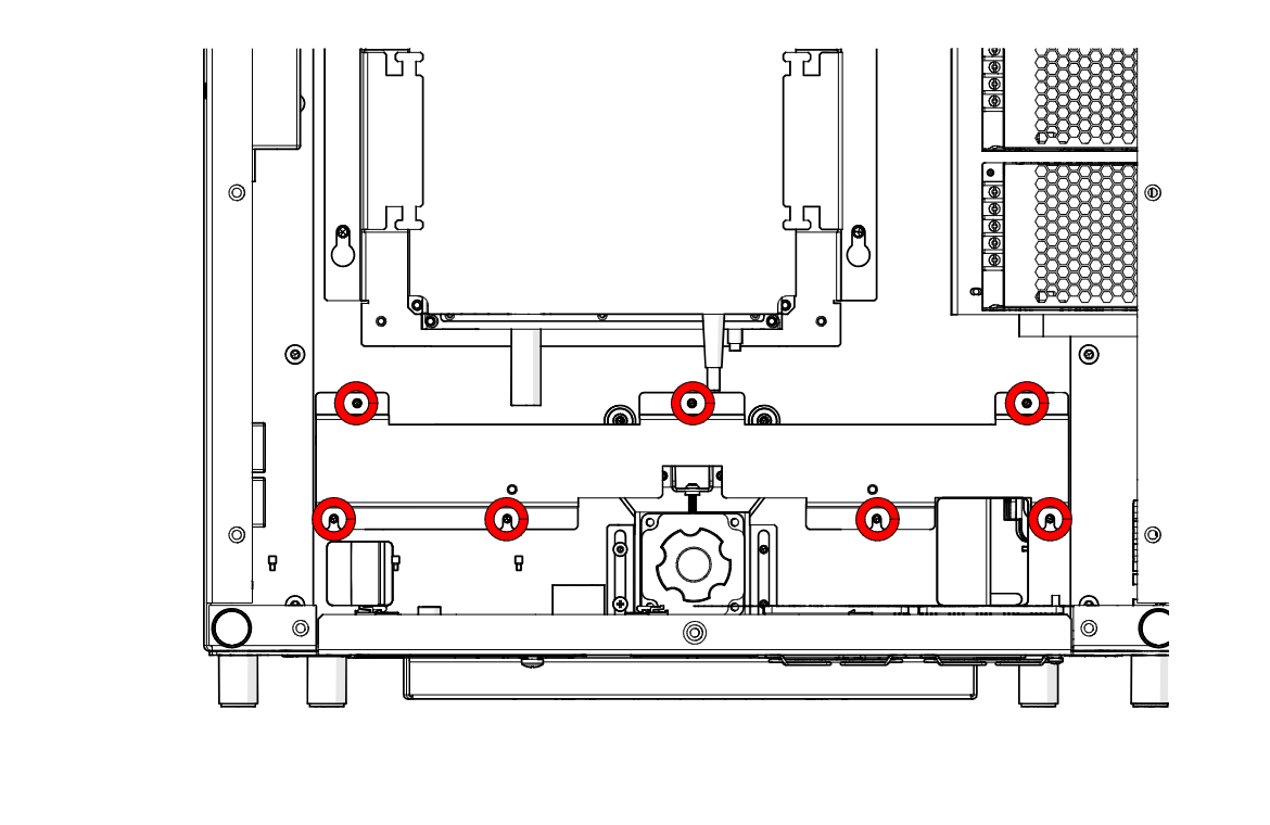
Remove Cover Screws
Loosen and remove the seven screws securing the cover over the z-axis motor (highlighted in red).
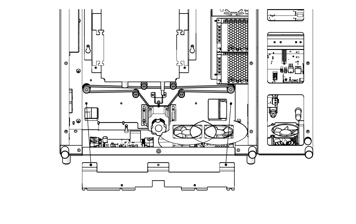
Remove Cover
Remove the cover.
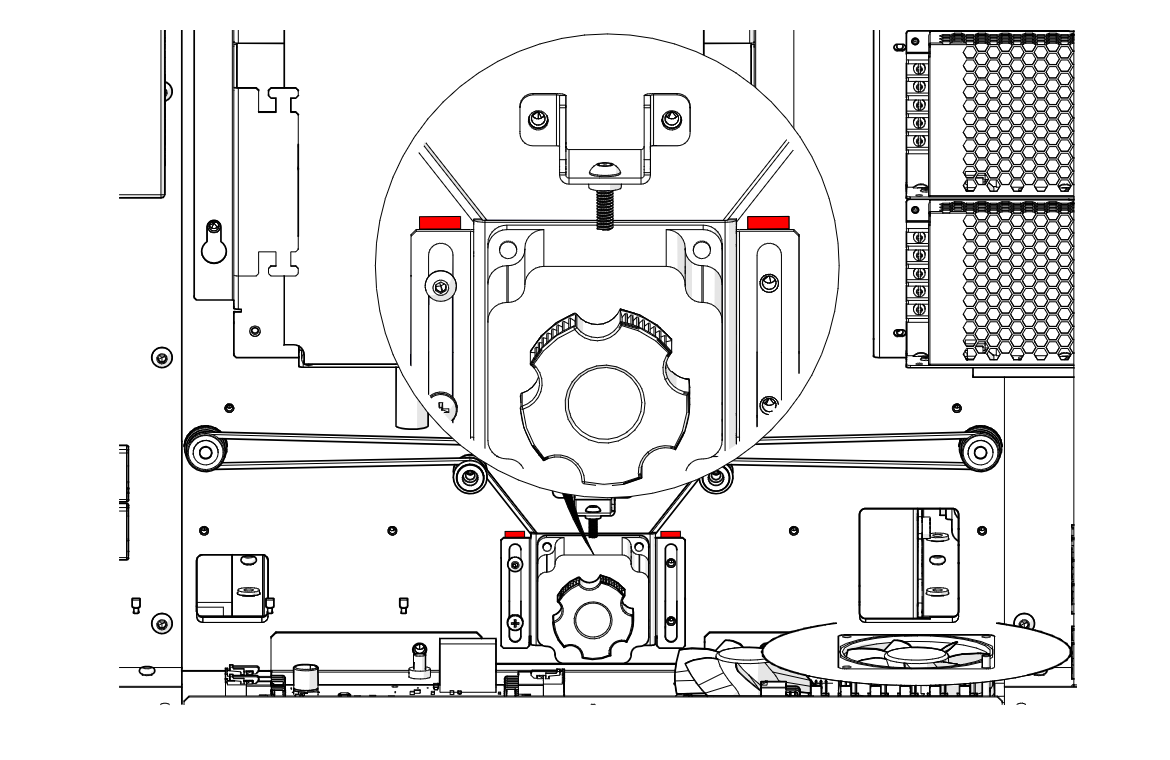
Mark Motor Height
Using a pencil or marker, mark the current height of the motor on both sides of its bracket (shown in red).
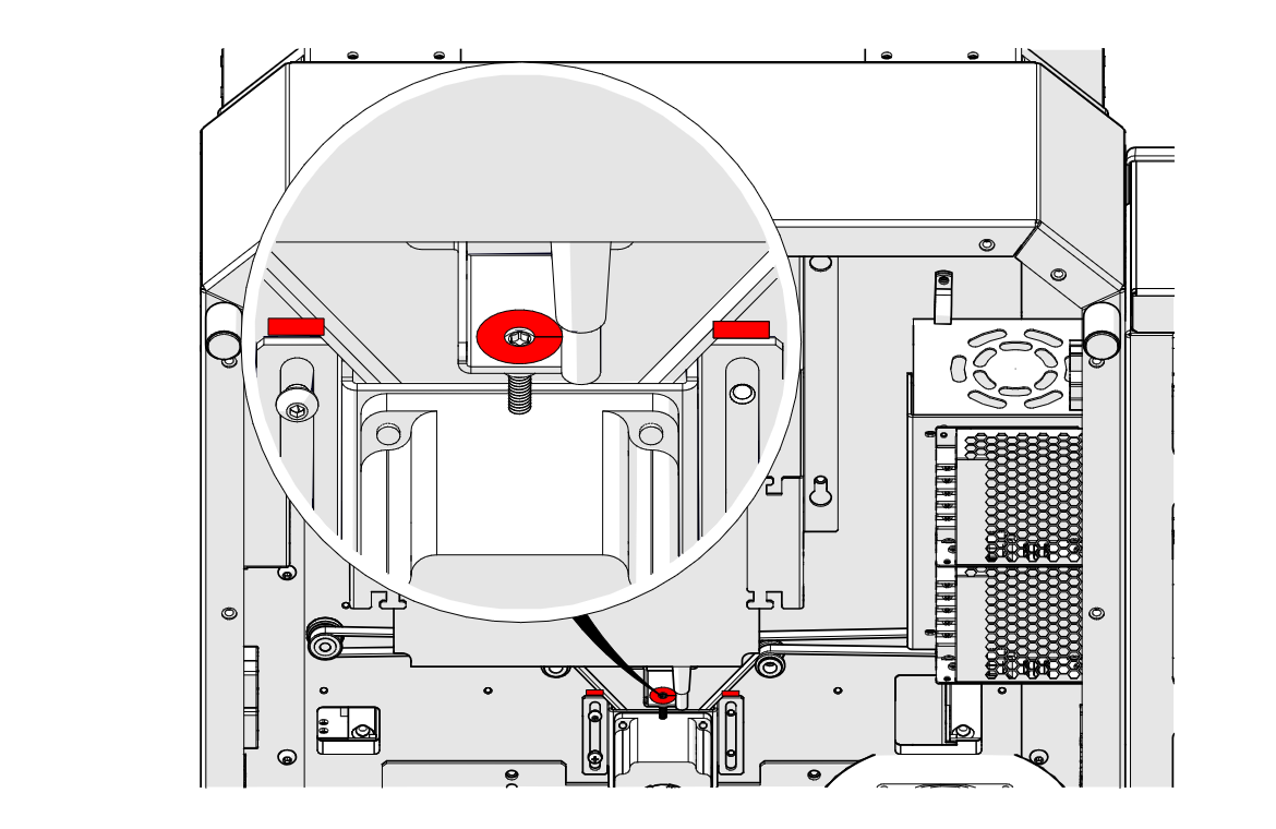
Loosen Tension Screw
Loosen the tension screw highlighted in red, but do not remove it.
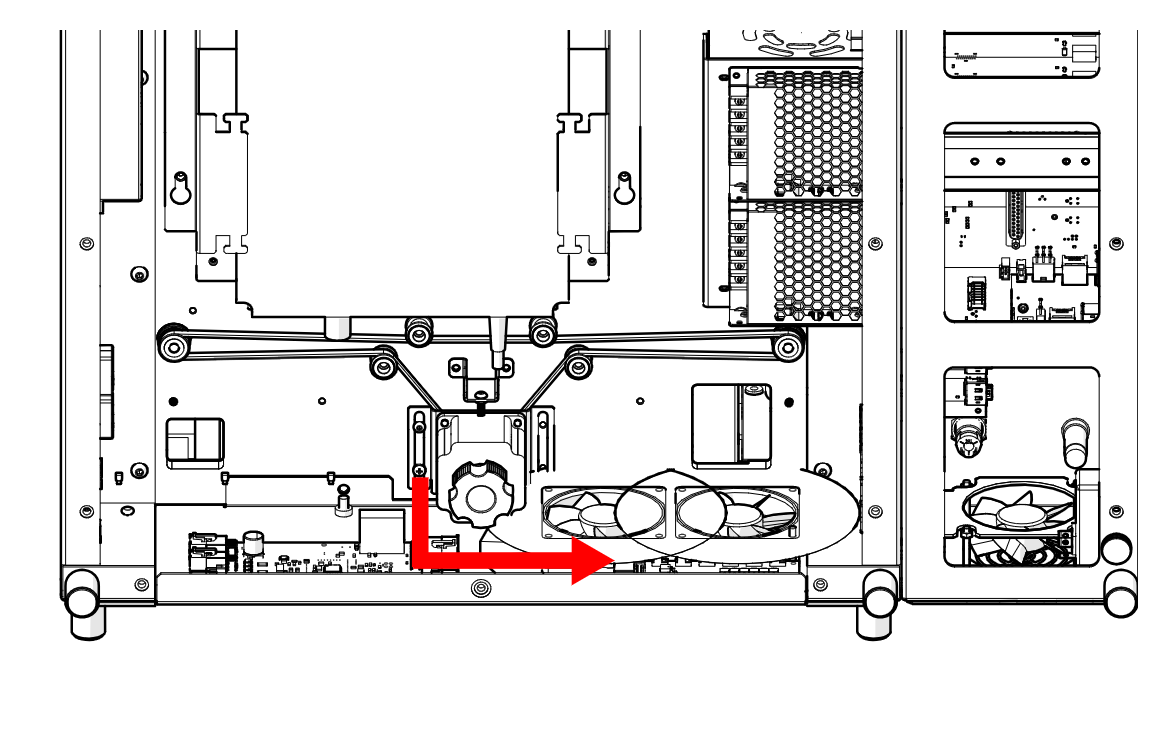
Disconnect Motor Harness
Follow the motor harness along the path of the arrow and disconnect it.
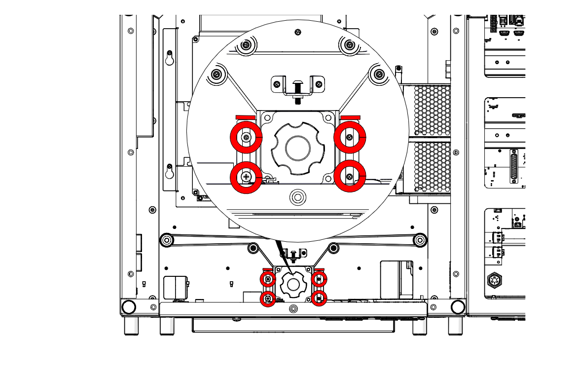
Remove Motor Screws
Loosen and remove the four motor screws (highlighted in red).
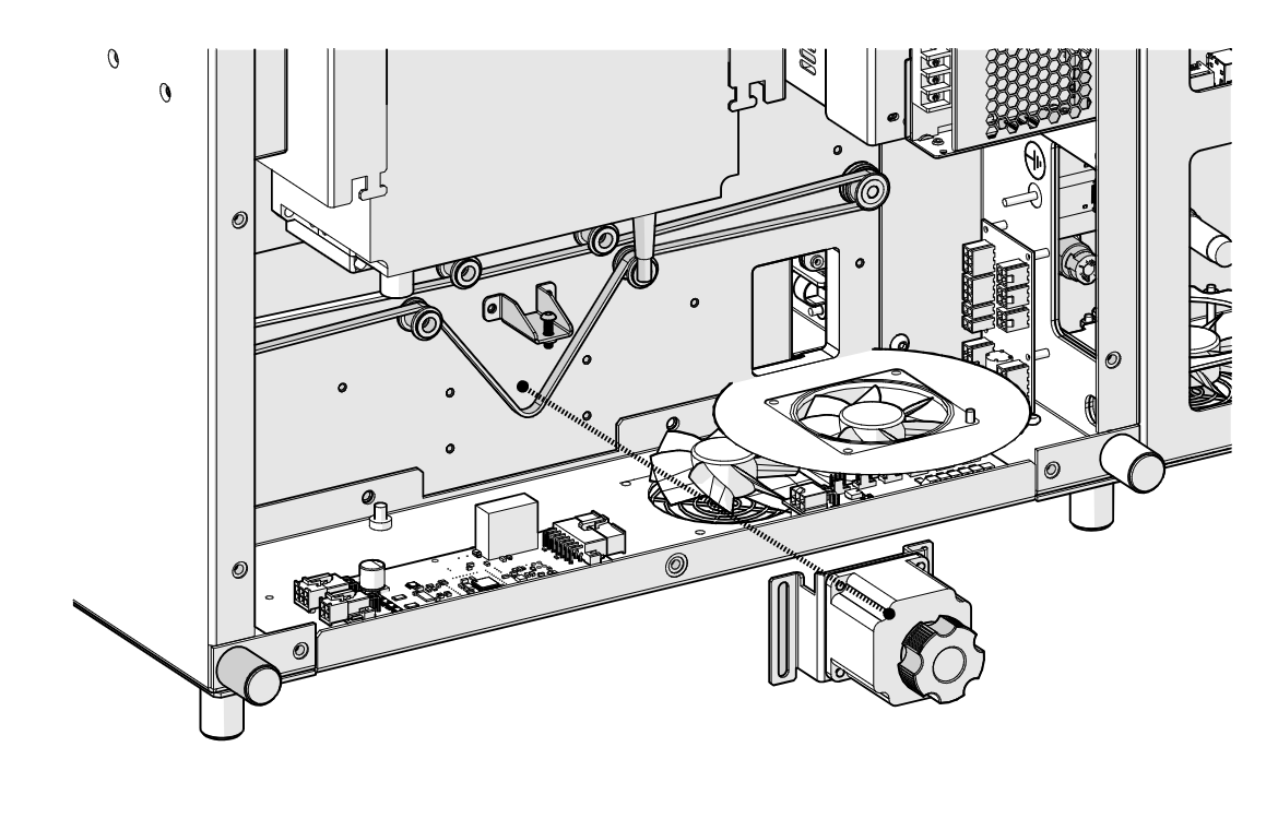
Remove Motor
Remove the motor from the engraver.
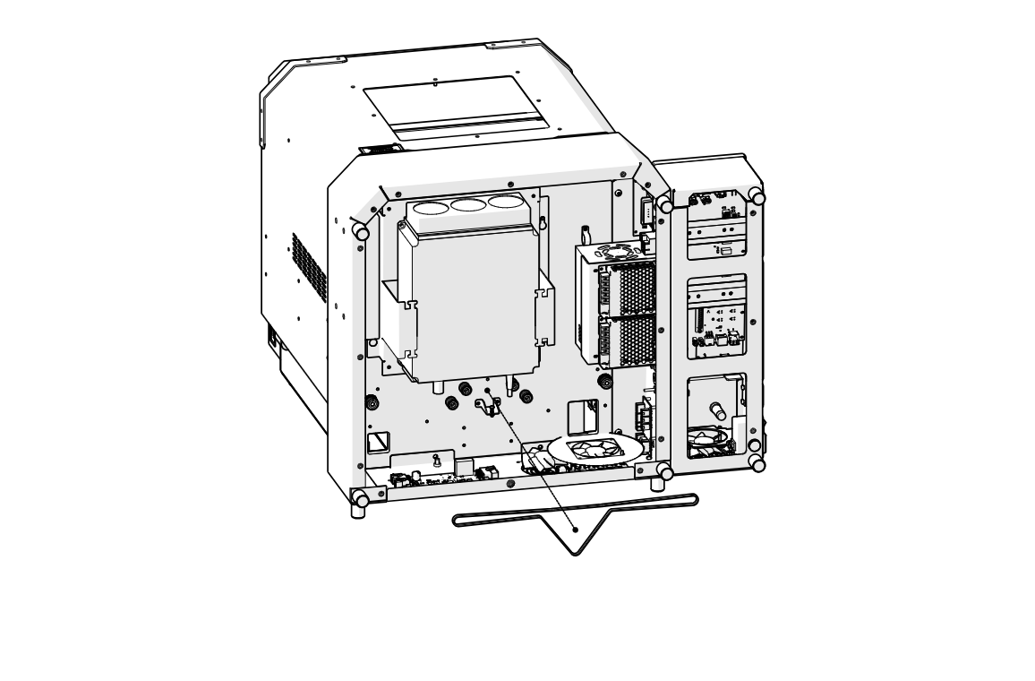
Remove Belt
Remove the z-axis belt.
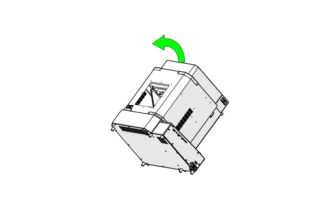
Return Engraver Upright
With a second person, tilt the engraver back to its upright position.
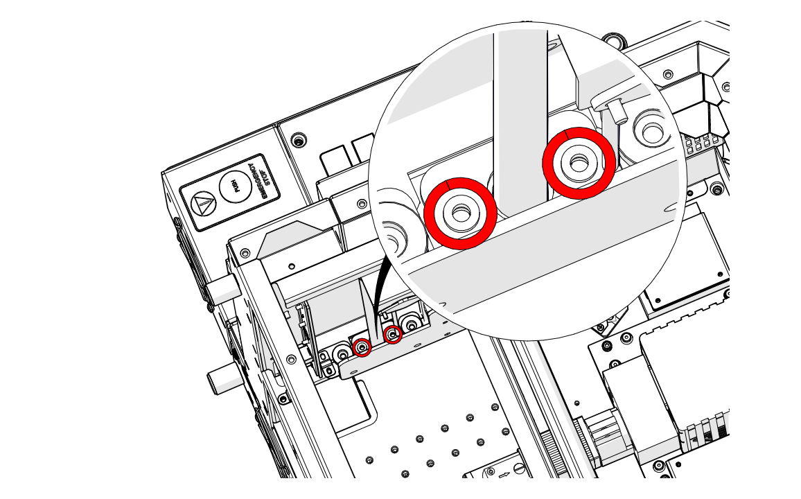
Remove Nut Screws
Loosen and remove the two screws securing the lead screw nut to the table bracket (highlighted in red).
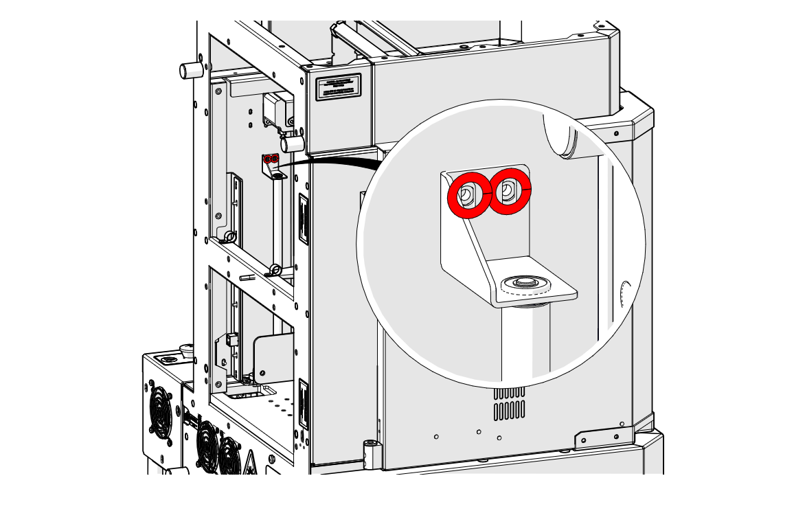
Remove Top Bracket Screws
Loosen and remove the two screws on the top lead screw bracket (highlighted in red).
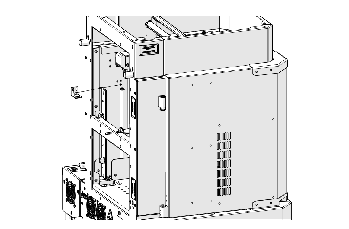
Remove Top Bracket
Remove the top bracket.
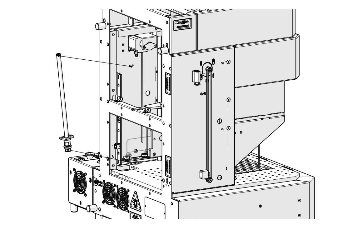
Remove Lead Screw
Lift the lead screw out of the engraver.
Lead Screw Installation
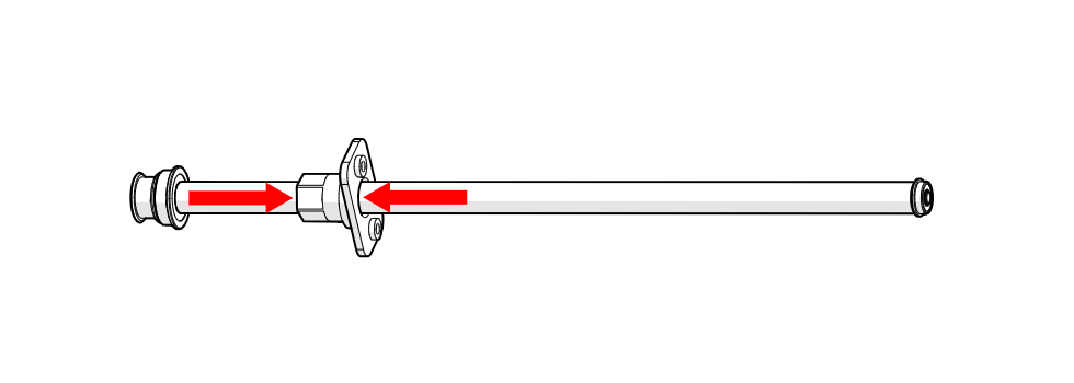
Check the Nut and Bracket
On the new LC0792 lead screw, make sure the lead screw nut and table bracket are pushed together.
Install Lead Screw
Place the lead screw into the engraver.
Install Top Bracket
Place the top bracket back in position.
Install Top Bracket Screws
Install the two bracket screws (highlighted in red), but do not fully tighten them yet.
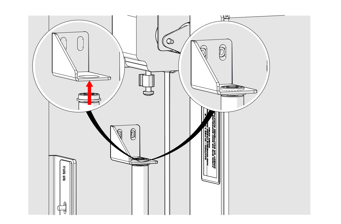
Seat Lead Screw
Seat the top of the lead screw in the bracket, as shown in the detail views.
Tighten Top Bracket Screws
Tighten the two bracket screws.
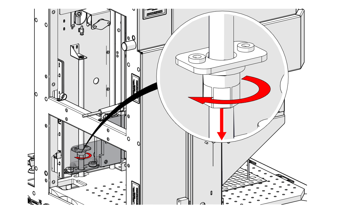
Lower Nut and Bracket
Turn the lead screw nut to lower the nut and table bracket into place.
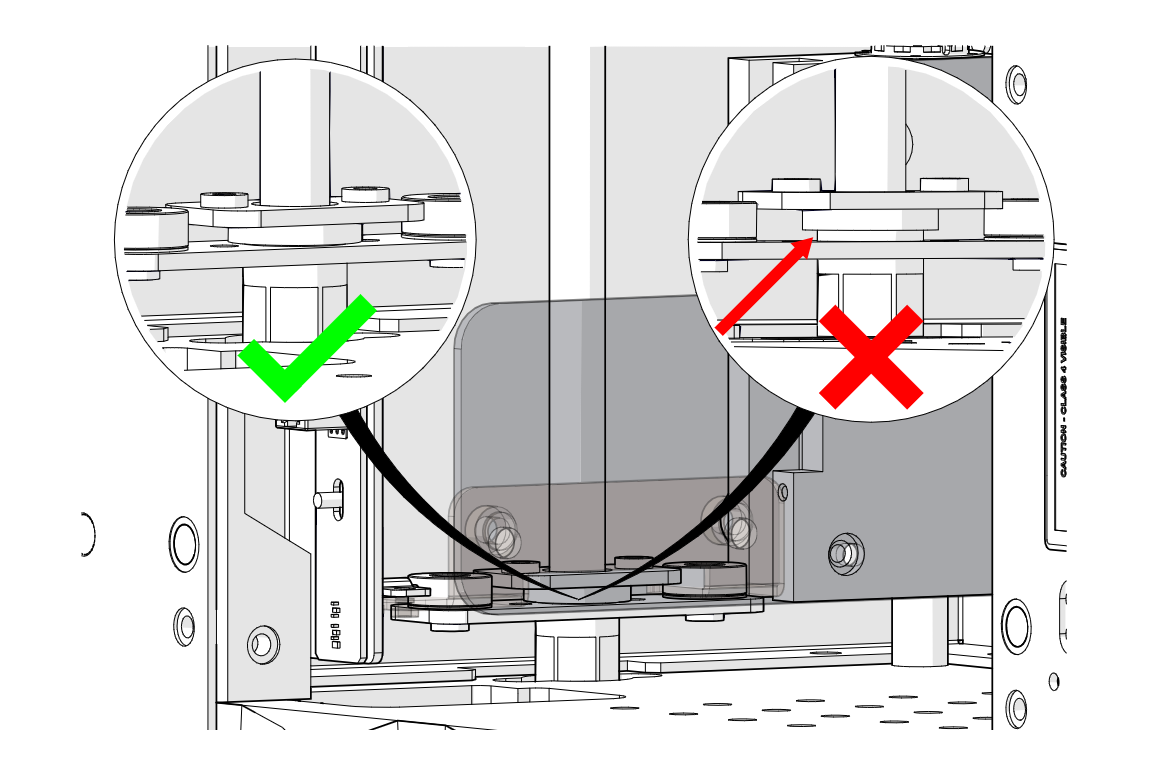
Check the Seating
Make sure the lead screw nut sits flush against the table bracket (left), with no gap between them (right).
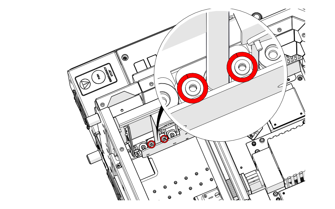
Install Nut Screws
Install and tighten the two nut screws (highlighted in red).
Tilt Engraver
Tilt the engraver back onto its back again.
Note: The engraver is heavy. Use two people to tilt it.
Install Belt
Install the z-axis belt.
Install Motor
Place the motor back into position.
Install Motor Screws
Install the four motor screws (highlighted in red), but do not fully tighten them yet.
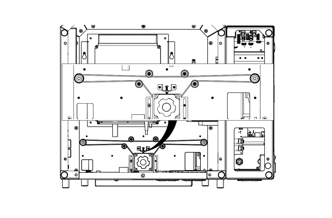
Check Belt Routing
Make sure the belt is routed correctly around the pulleys, as shown.
Connect Motor Harness
Route the harness along the path of the arrow and reconnect it.
Tighten Tension Screw
Tighten the tension screw highlighted in red.
Match the Height Marks
Continue tightening until the motor lines up with the marks you made earlier, then tighten the four motor screws.
Install Cover
Reinstall the cover over the motor.
Install Cover Screws
Install and tighten the seven cover screws.
Install Bottom Panel
Set the bottom panel back on the engraver.
Install Bottom Panel Screws
Install and tighten the screws around the bottom panel.
Return Engraver Upright
With a second person, tilt the engraver back to its upright position.
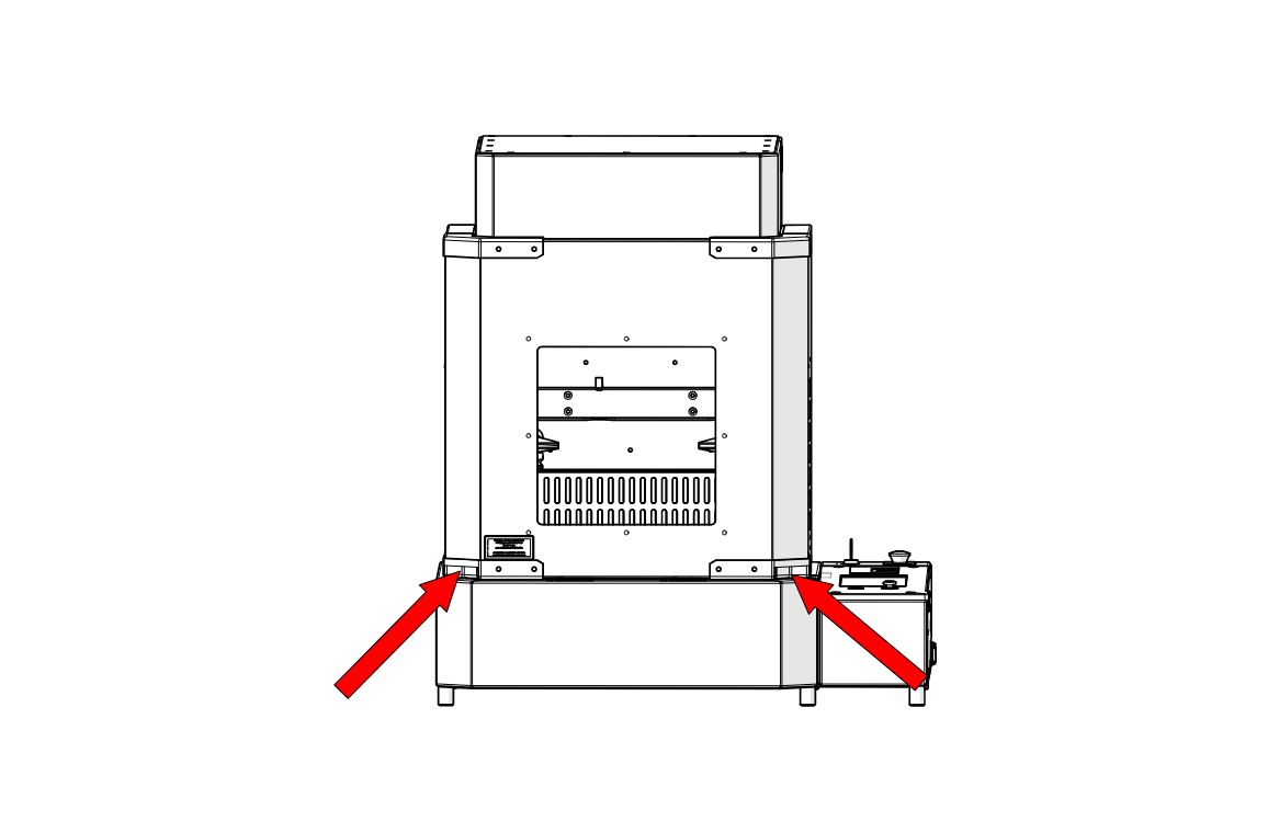
Lift the Door
Lift the door using the handles at the bottom corners, shown by the arrows.
Remove Second Bracket Screws
Loosen and remove the two screws on the second shipping bracket.
Remove First Bracket Screws
Loosen and remove the two screws on the first shipping bracket.
Remove Shipping Brackets
Remove both shipping brackets and store them for future use.
Install Side Panel
Place the side panel back on the engraver.
Install Side Panel Screws
Install and tighten the side panel screws.
Install Lower Rear Panel
Slide the lower rear panel and exhaust duct back into place.
Install Lower Rear Panel Screws
Install and tighten the eight lower rear panel screws.
Install Upper Rear Panel
Place the upper rear panel back on the engraver.
Install Upper Rear Panel Screws
Install and tighten the eight upper rear panel screws.
Install Top Panel
Set the top panel back on the engraver.
Install Top Panel Screws
Install and tighten the screws around the edge of the top panel.
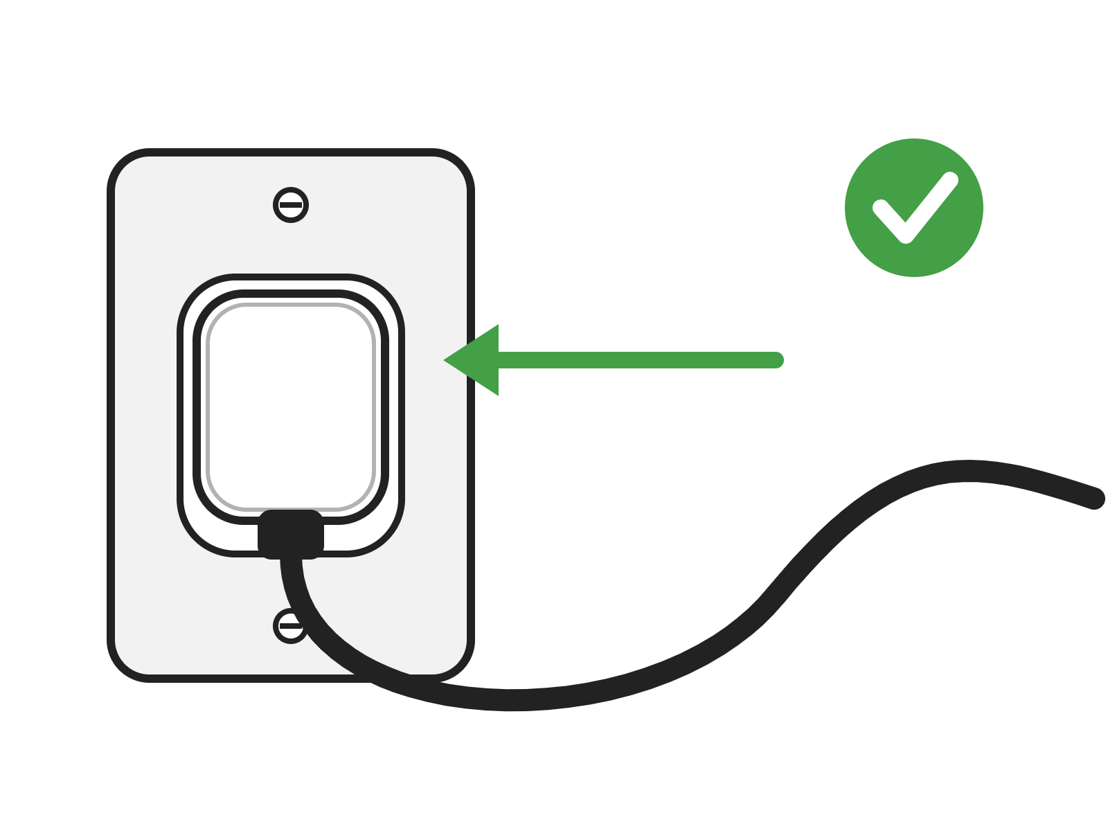
Connect to Power
Plug the power cord back into the engraver.