
This guide covers replacing the X-axis motor on the Fusion Ascent 24. The motor and its mount come out of the right-hand end of the X-axis assembly as one unit. After the new motor is installed, the X-axis belt is tensioned and tracked. Read through the whole procedure before you start. Directions such as left-hand and right-hand are given as if you are facing the front of the machine. In the images, orange marks parts to remove, green marks parts to install, and blue marks screws to loosen or adjust without removing.
Parts Required
- Replacement X-Axis Motor (Fusion Ascent)
Tools Required
- 3/32″ Allen Wrench
- 7/64″ Allen Wrench
- 5/32″ Allen Wrench
- Small Flathead Screwdriver
- Small Phillips Screwdriver
- Epilog Belt Tensioning Tool
- Fine-tip marker
Safety First: Turn off the engraver and unplug it from power before removing any panels. Wear safety glasses throughout this procedure.
X-Axis Motor Removal
Turn Off Engraver
Turn off the engraver.
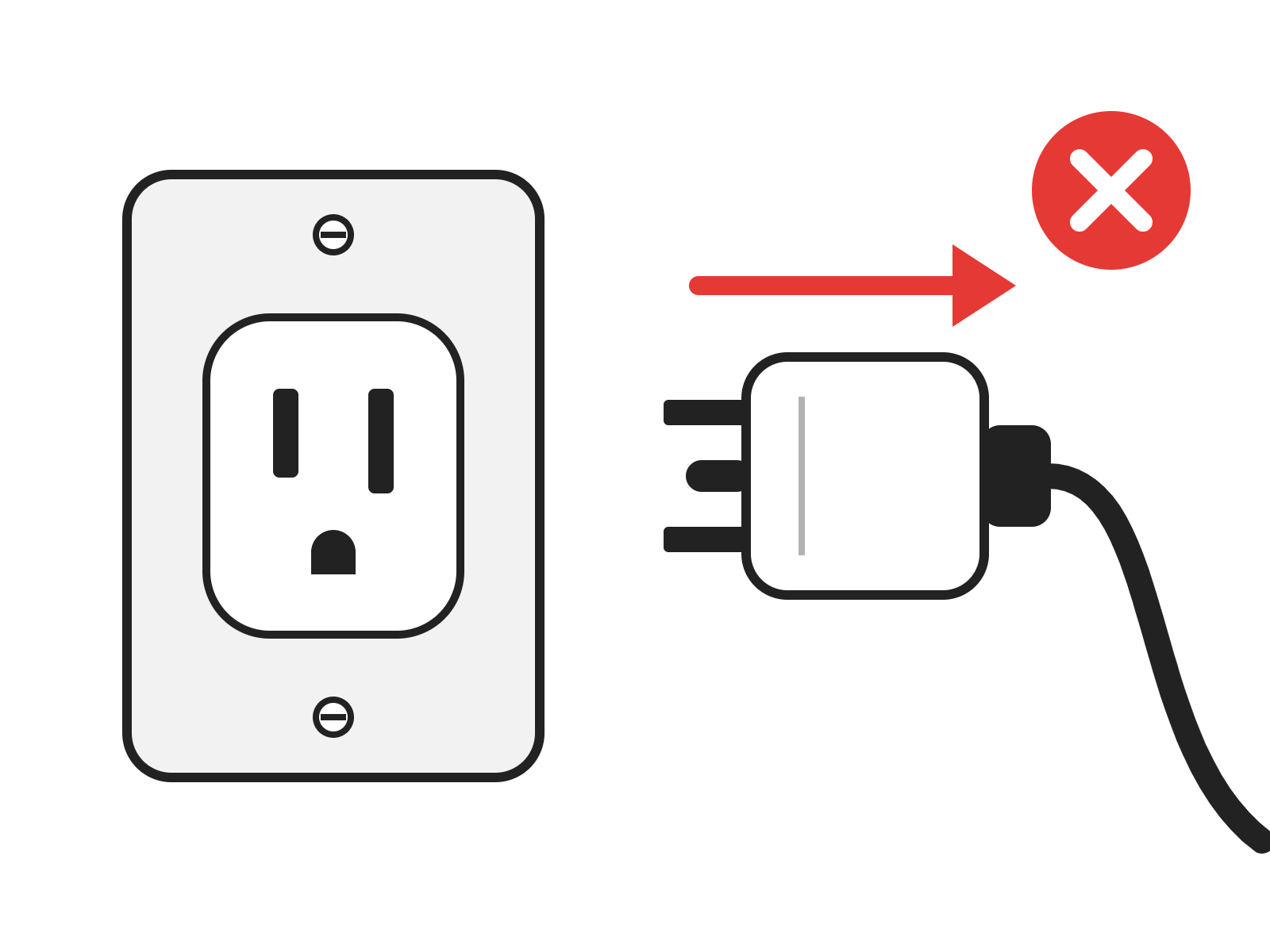
Disconnect from Power
Unplug the engraver from its power source.
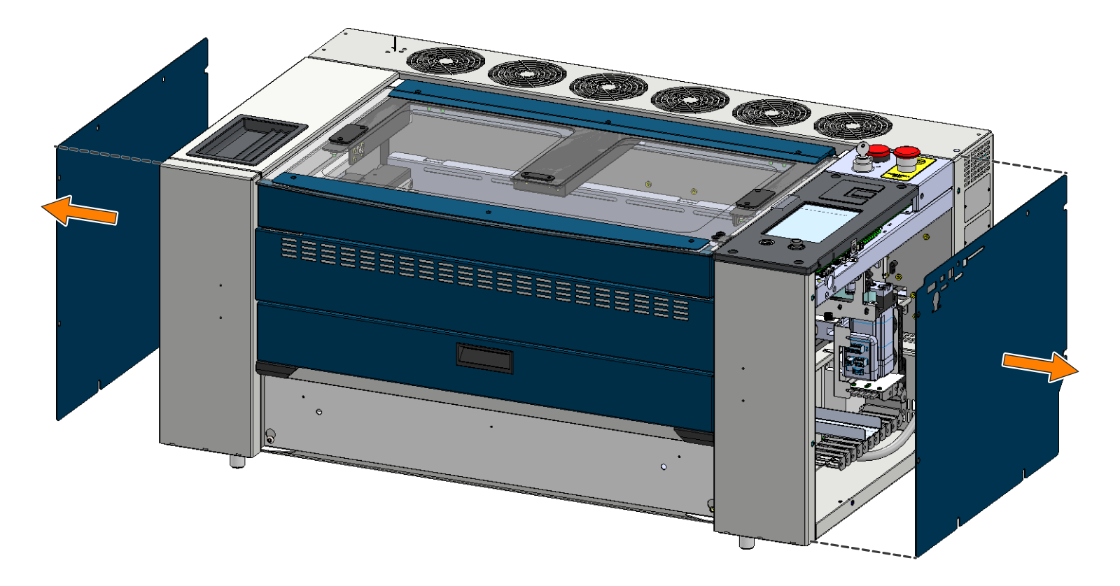
Remove the Side Panels
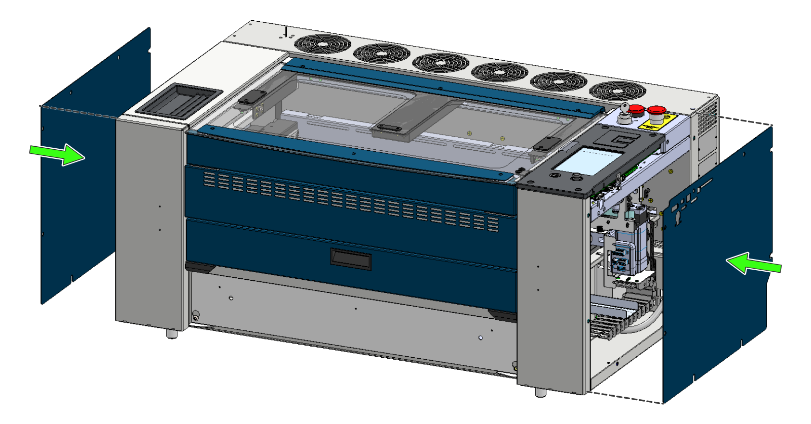
Remove the right-hand side panel, then the left-hand side panel.
Center the X-Axis
Pull the X-axis assembly by hand to the center of the machine.
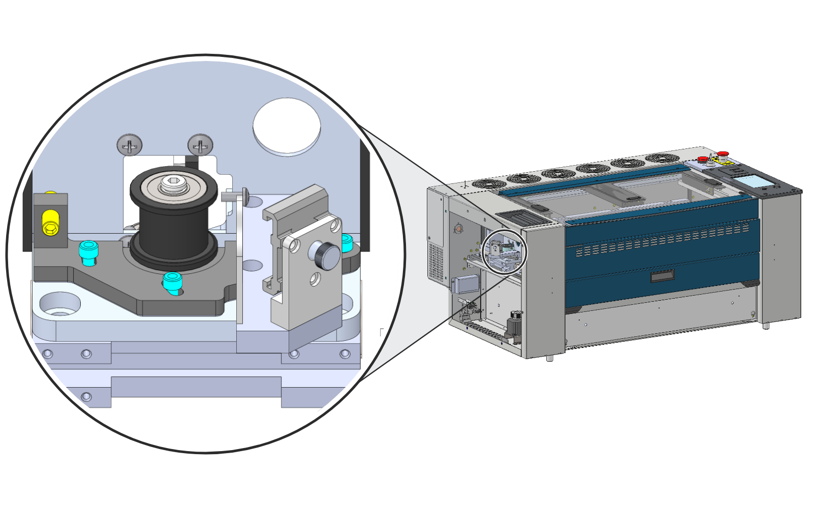
Release the Belt Tension
At the left-hand side of the machine, loosen the three Allen screws (blue), then loosen the tensioner screw (yellow).
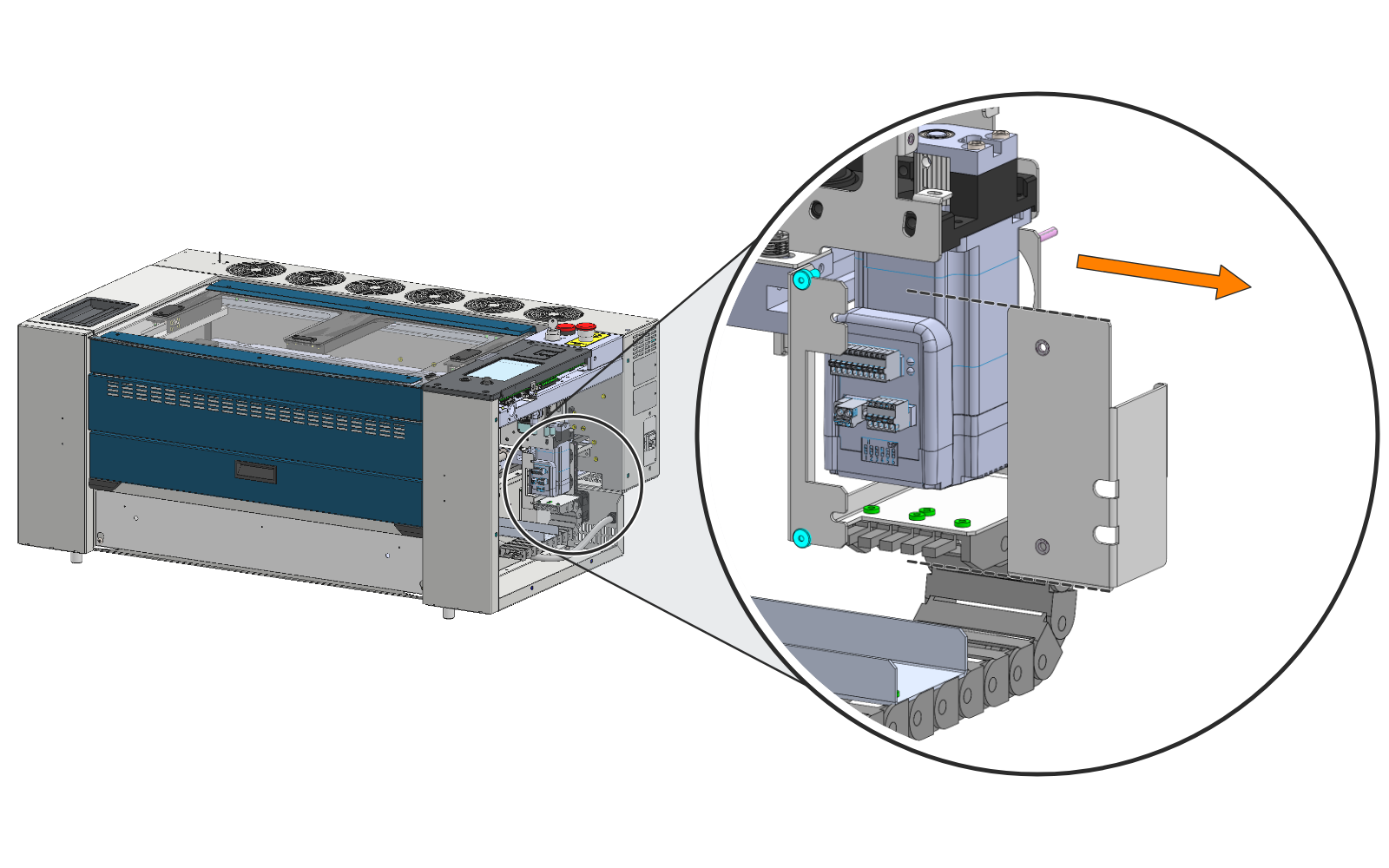
Remove the Harness Cover
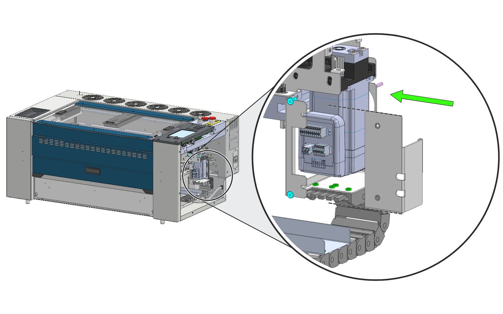
At the right-hand side of the machine, loosen the two screws (blue) that secure the harness cover. Do not remove them. Slide the harness cover out toward the right-hand side of the machine so its slots clear the screws.
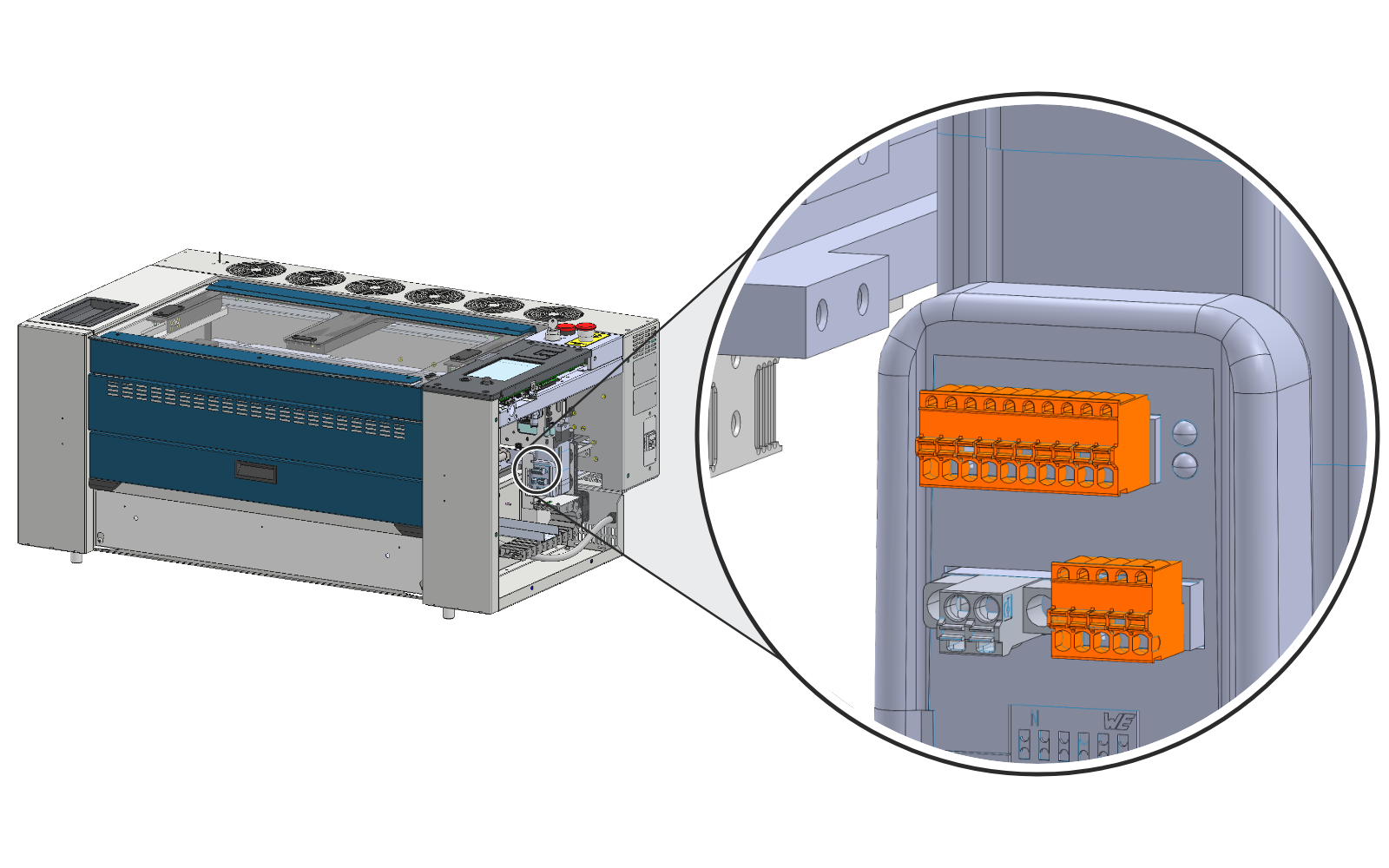
Disconnect the Motor
Disconnect the two electrical connectors (orange) from the X-axis motor.
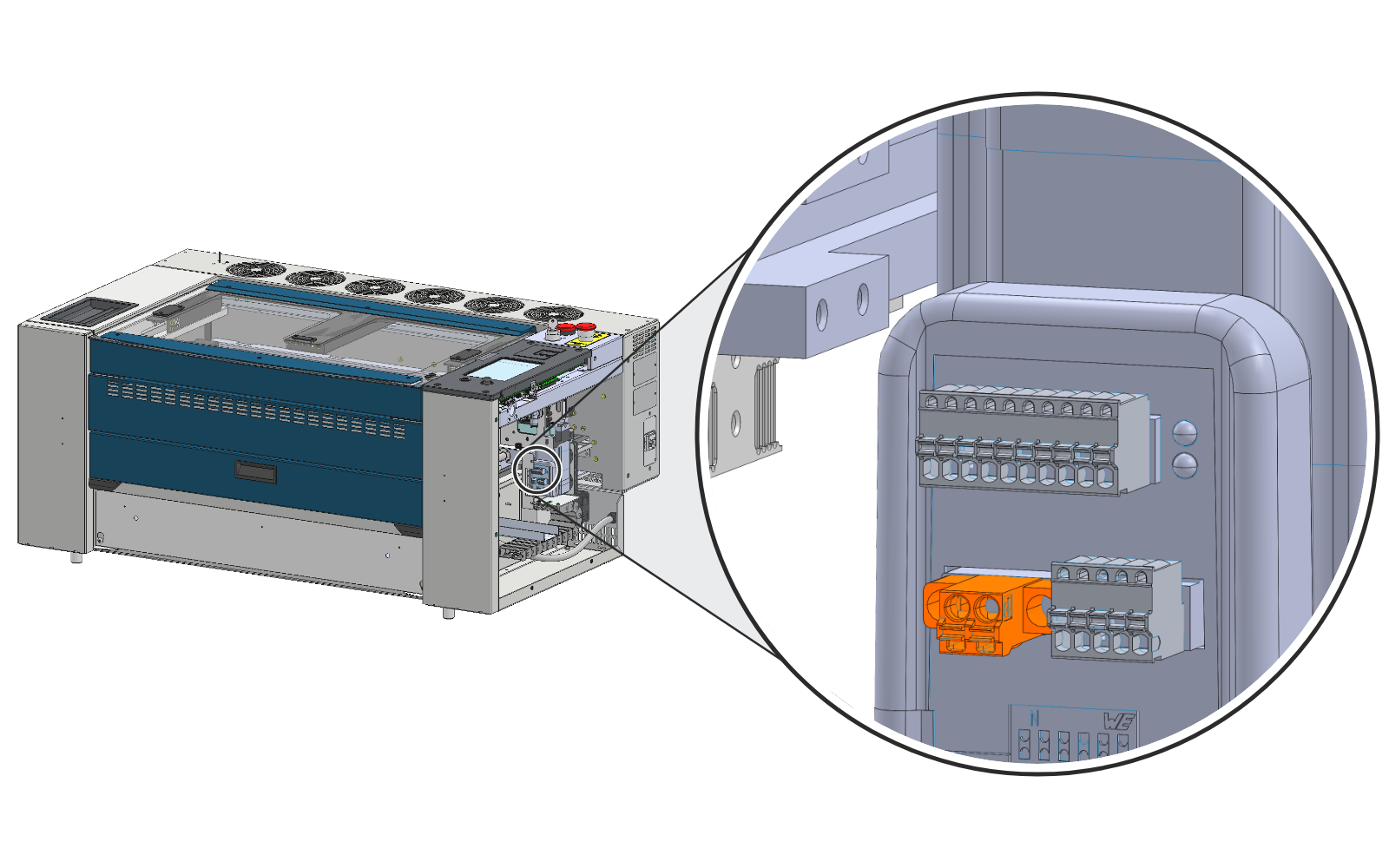
Unscrew the Power Connector
Using a small flathead screwdriver, loosen the two small screws that secure the power connector (orange), then unplug the power connector from the motor.
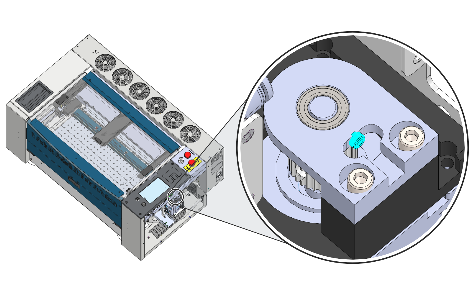
Loosen the Nylon Screw
Loosen the small nylon screw (blue) that secures the X-motor end bearing.
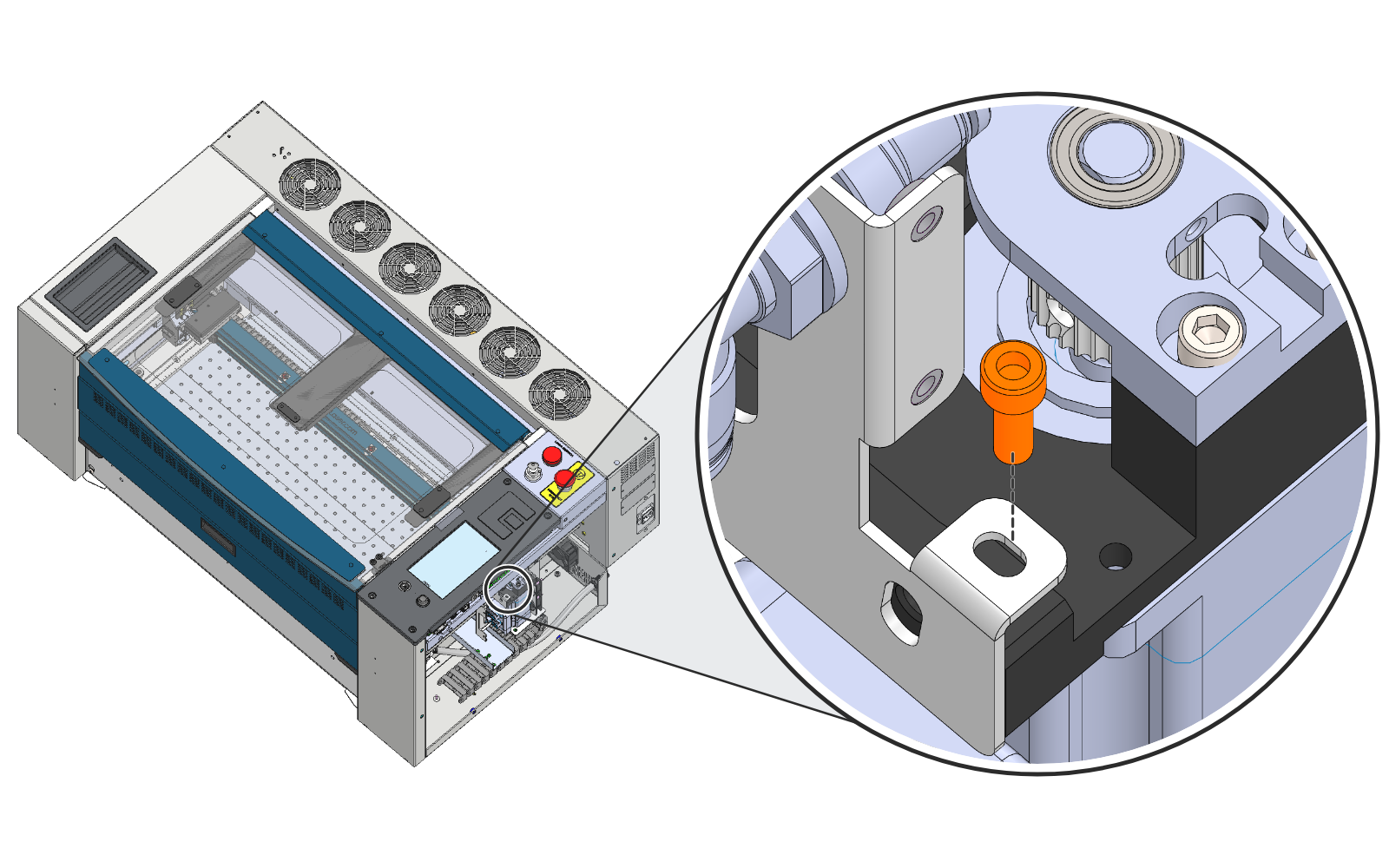
Remove the Tilt Control Screw
Remove the tilt control (tracking adjustment) screw (orange) from the tab on the front of the motor mount.
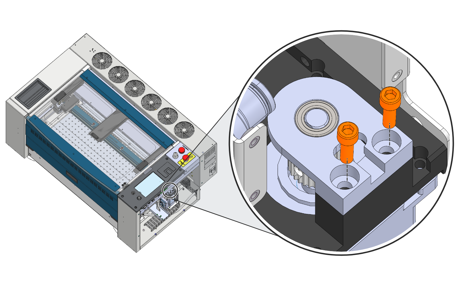
Remove the Bearing Support Screws
Remove the two screws (orange) that secure the end bearing support.
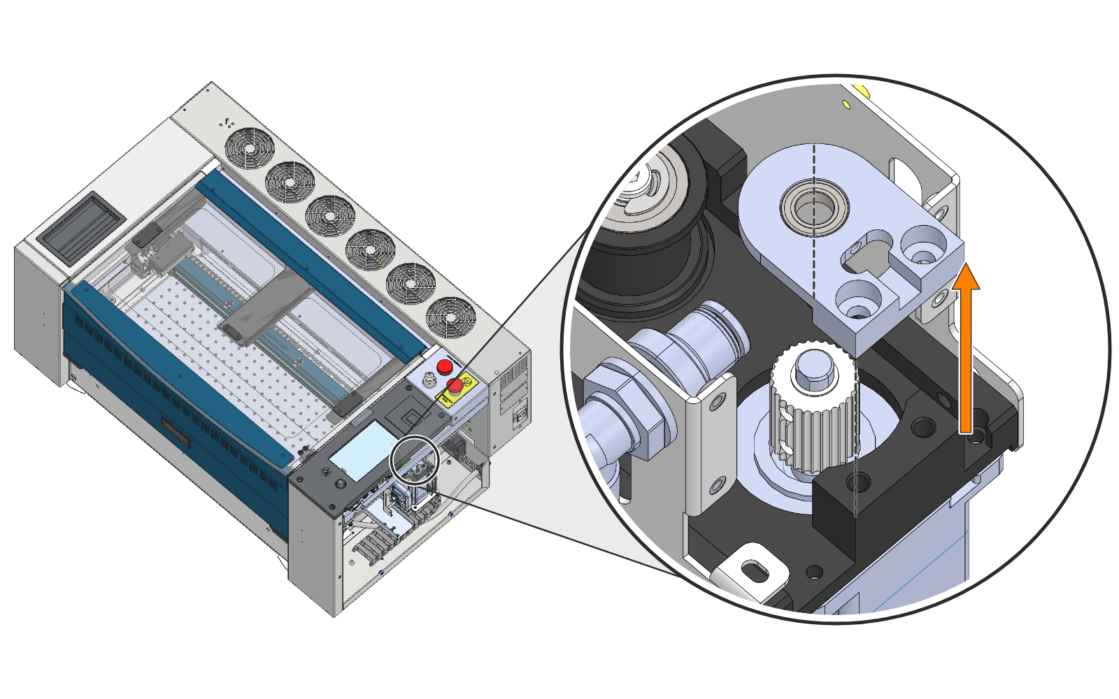
Remove the End Bearing Support
Lift the end bearing support off the motor pulley shaft.
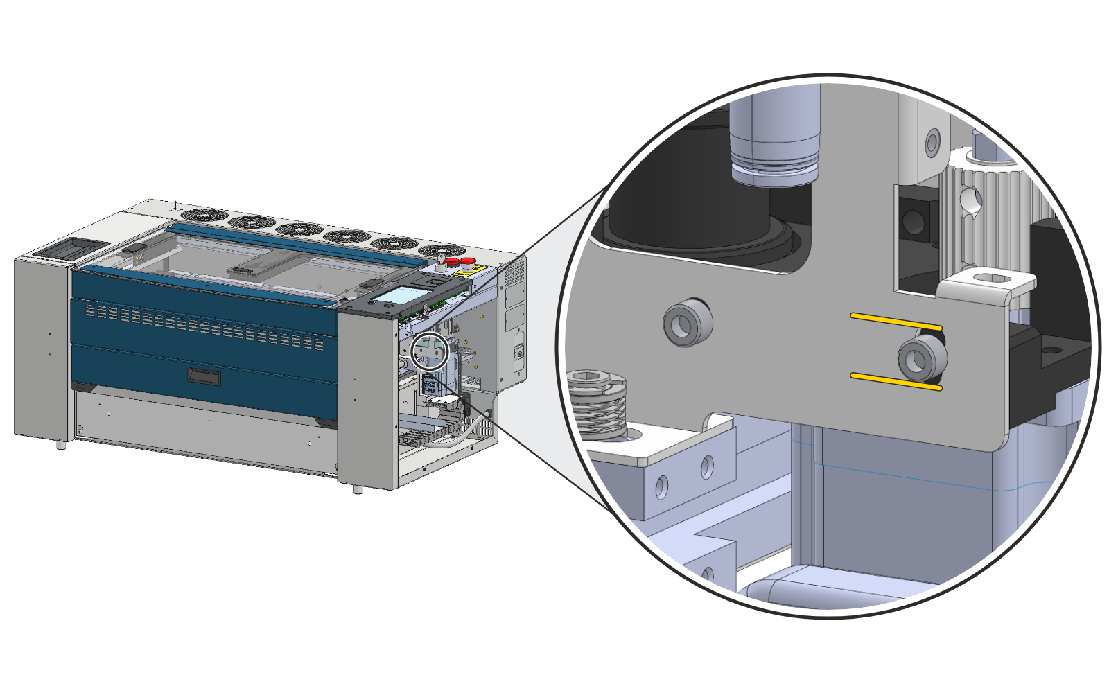
Mark the Front Screw Position
With a fine-tip marker, draw a line above and below the front screw nearest the motor (shown in yellow). These marks make it easier to set the X-axis belt tracking when the new motor is installed.
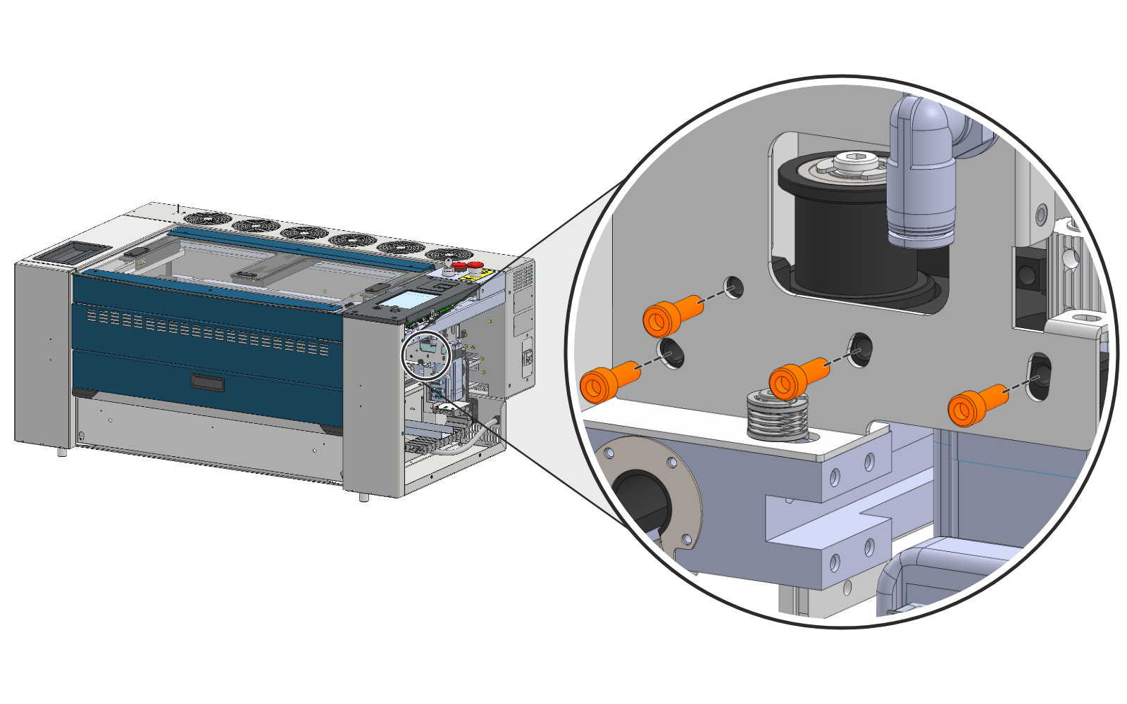
Remove the Front Screws
Remove the four screws (orange) on the front of the X-axis assembly that secure the motor mount.
Remove the Rear Screws
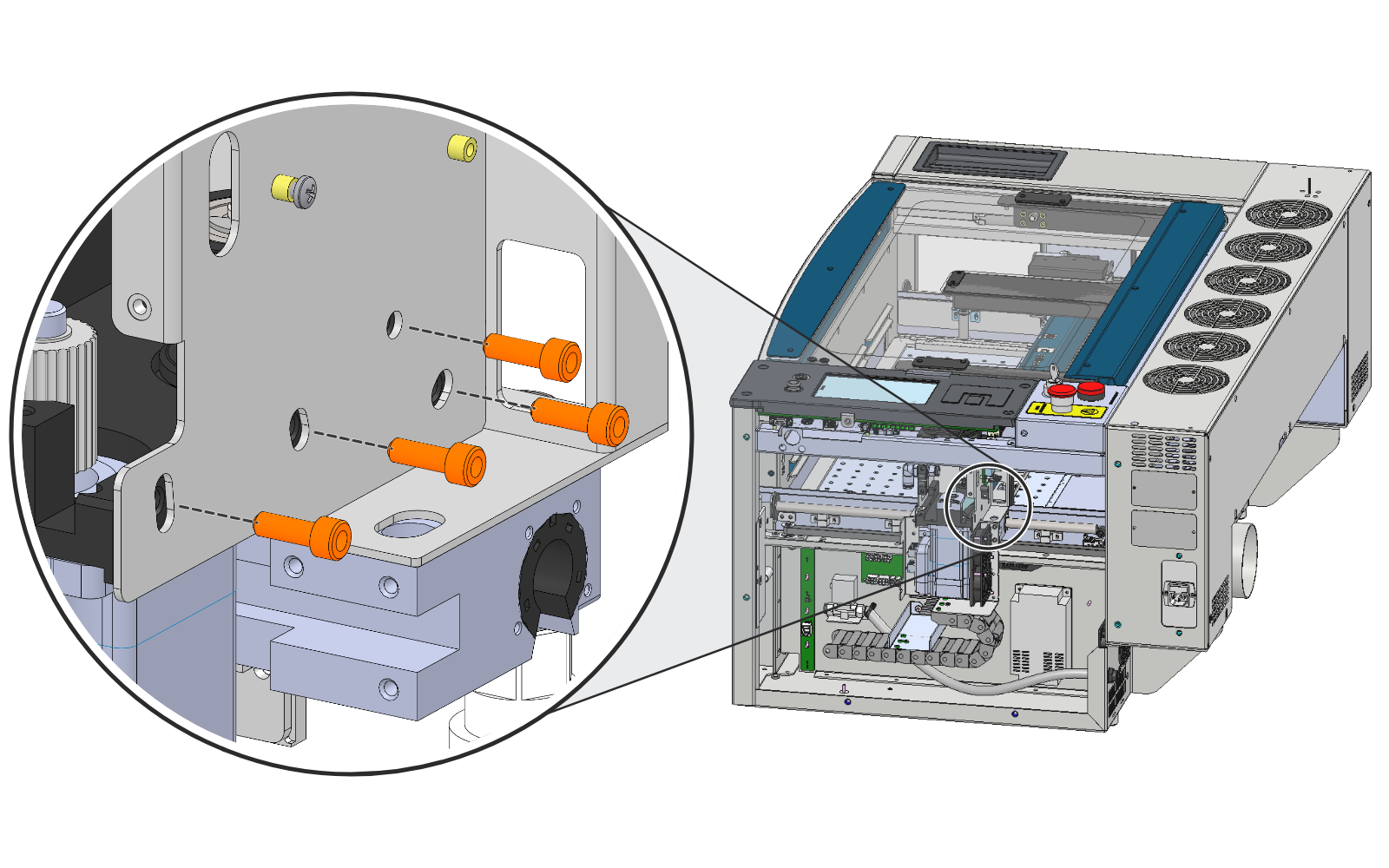
Remove the four screws (orange) on the rear of the X-axis assembly that secure the motor mount.
Remove the Motor Assembly
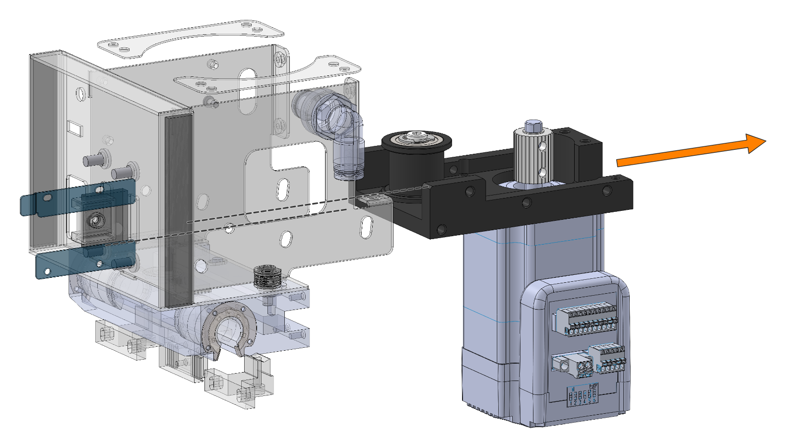
Slide the motor and mount assembly out of the right-hand end of the X-axis assembly, slipping the X-axis belt off the motor pulley.
Separate the Motor from the Mount
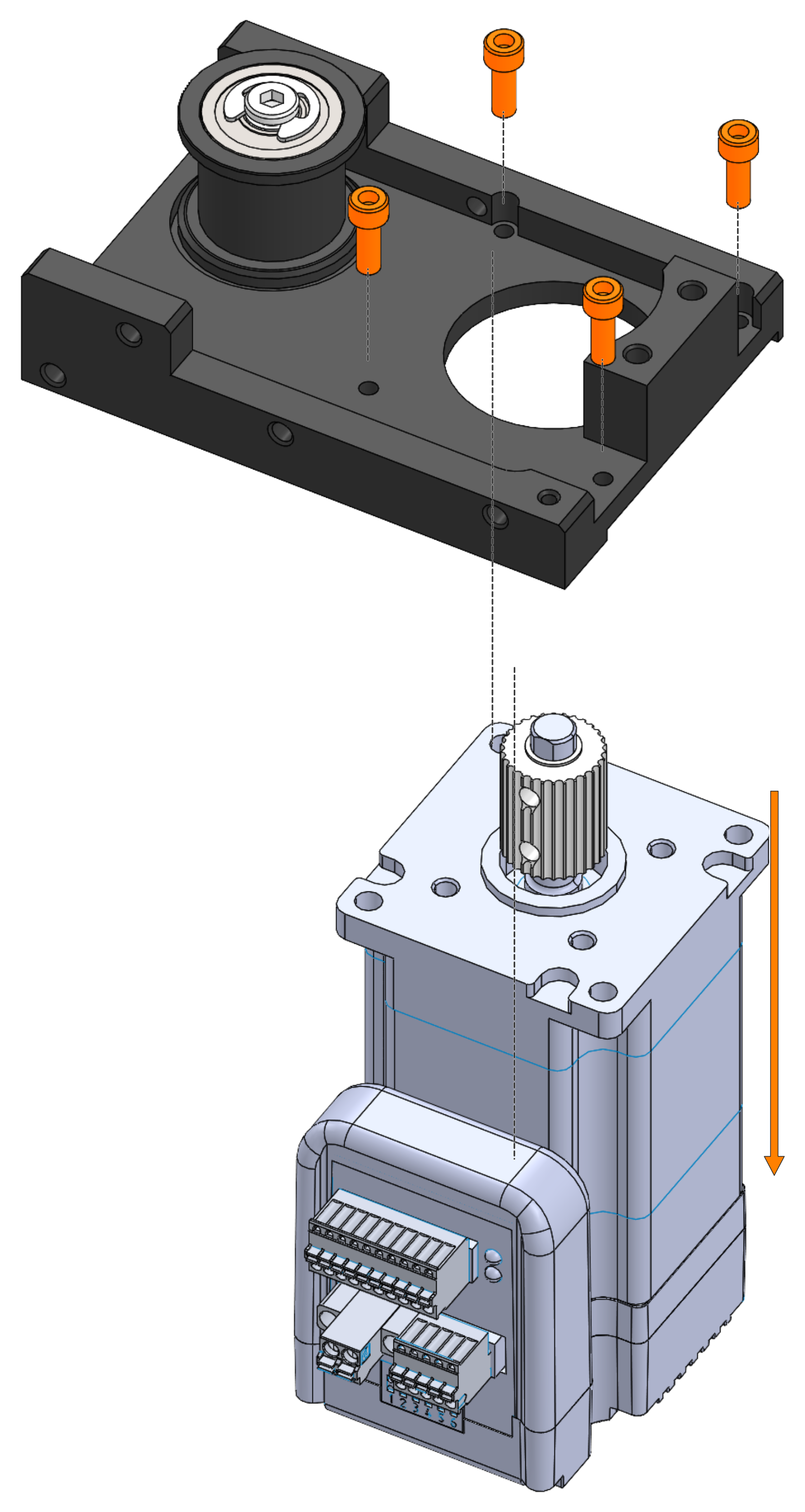
Remove the four screws (orange) that secure the motor to the motor mount, then lower the motor out of the mount.
X-Axis Motor Installation
Install the New Motor in the Mount
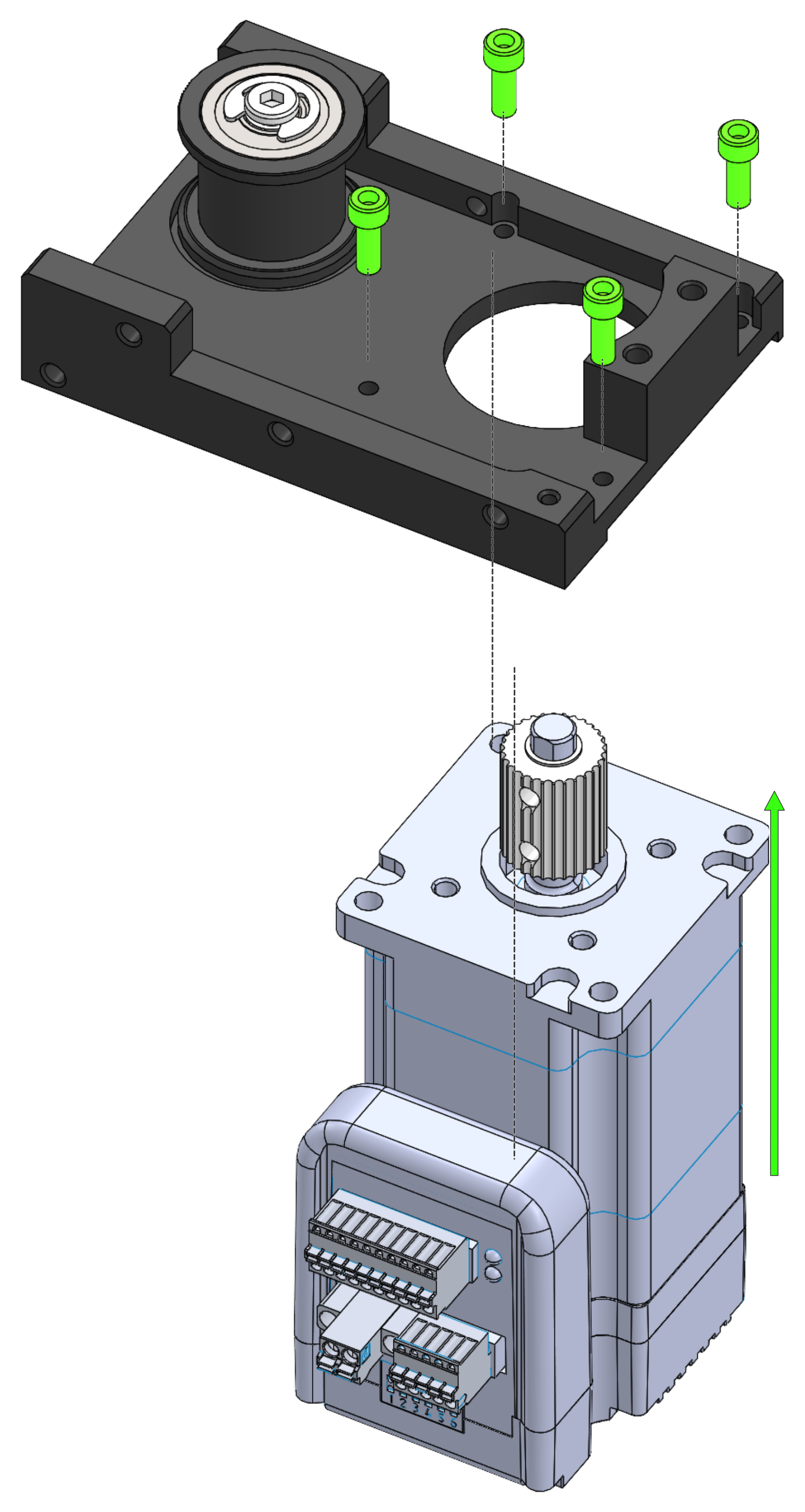
Orient the new motor with the electrical connections facing you and the idler pulley on the motor mount to your left. Install the motor into the motor mount and install the four mounting screws (green).
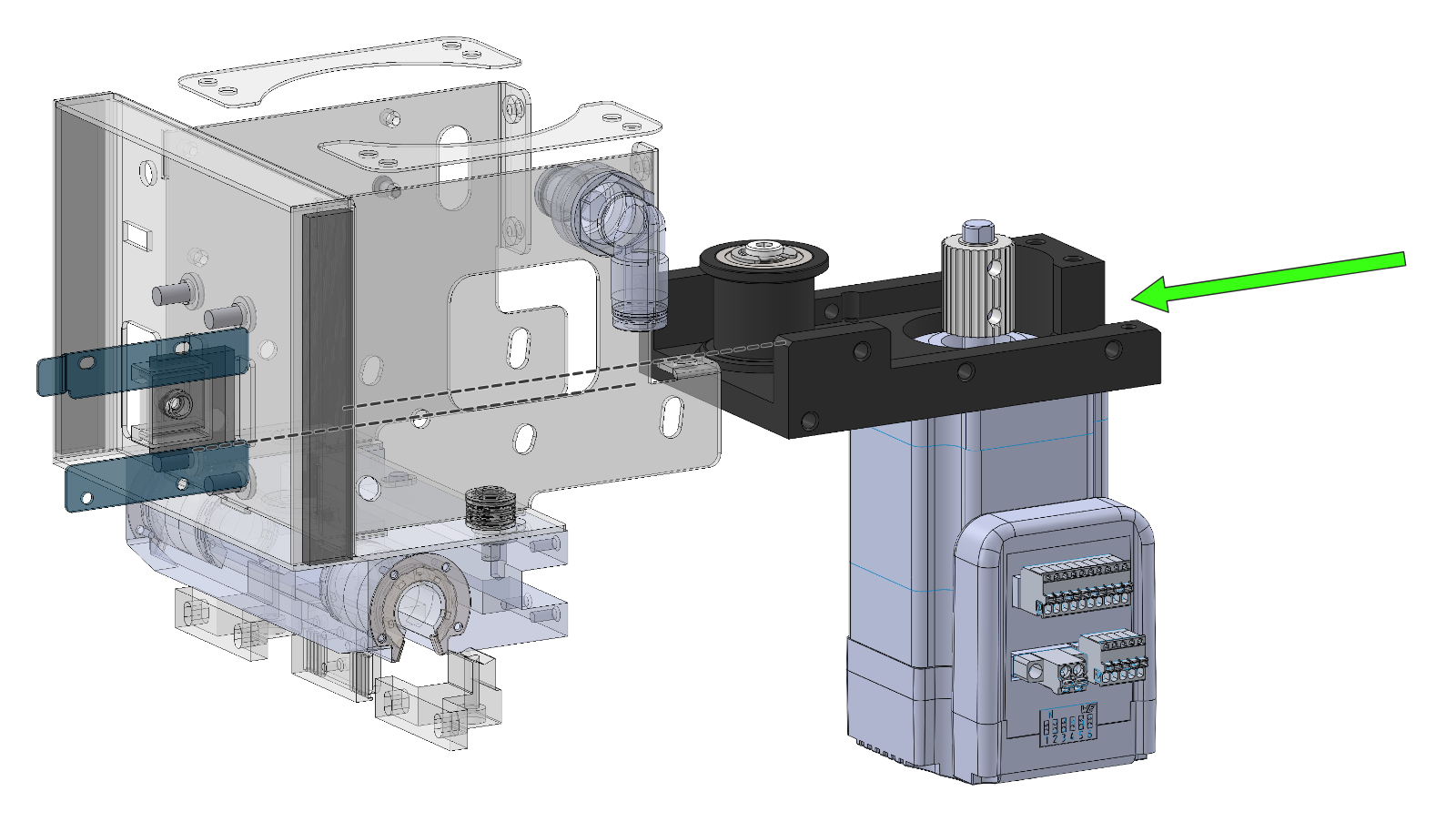
Install the Motor Assembly
Slide the motor and mount assembly into the right-hand end of the X-axis assembly. As it goes in, route the X-axis belt around the motor pulley and the idler pulley.
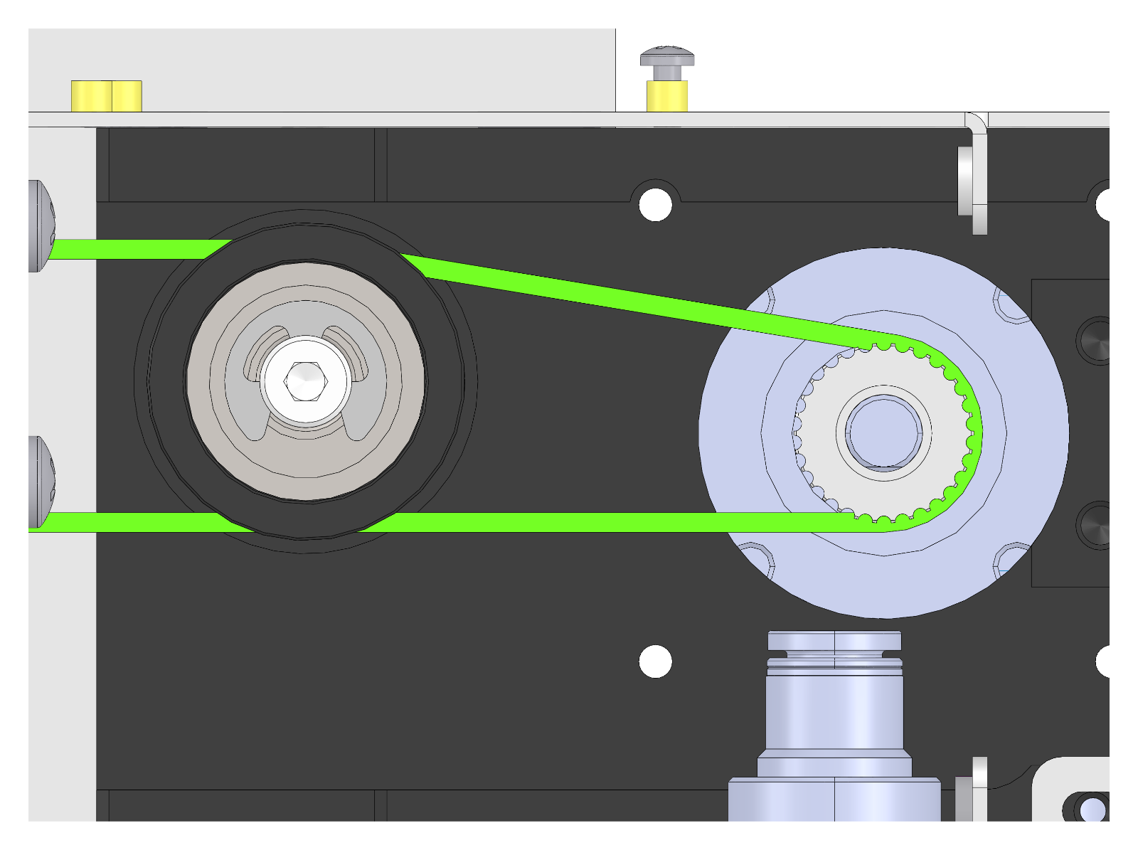
Check the Belt Routing
Make sure the X-axis belt wraps around both the motor pulley and the idler pulley, as shown.
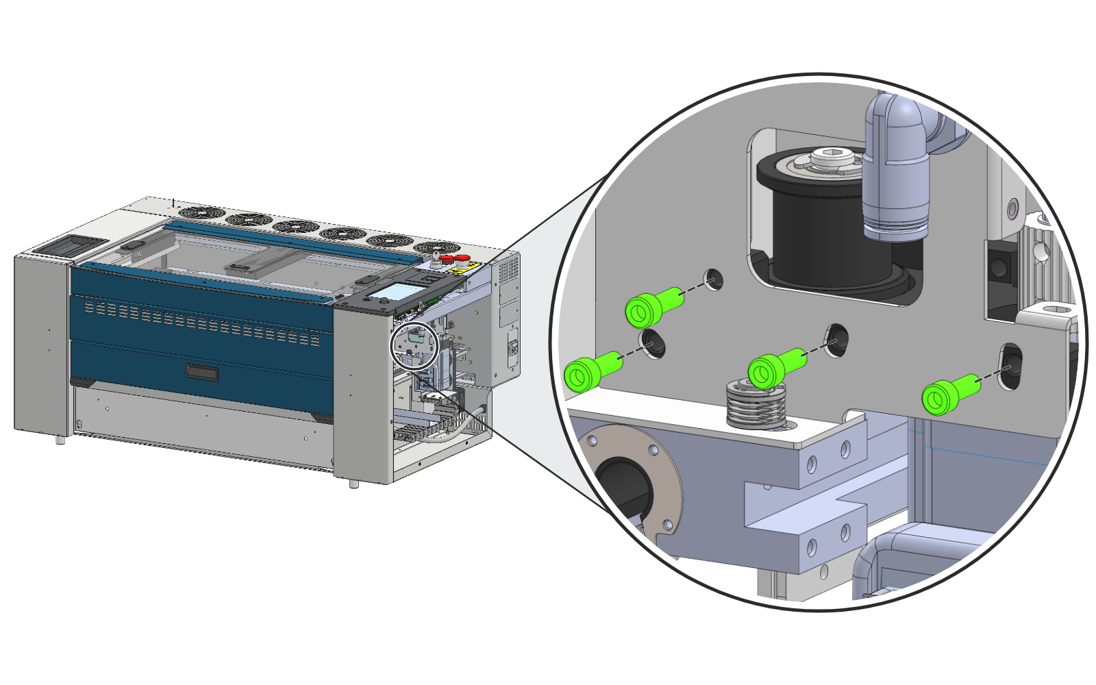
Install the Front Screws
Install the three front screws in the slotted holes and tighten them only until they stop. Do not snug them yet. Install the remaining front screw (the single screw in the round hole) and snug it. This screw is a pivot for adjusting the belt tracking later.
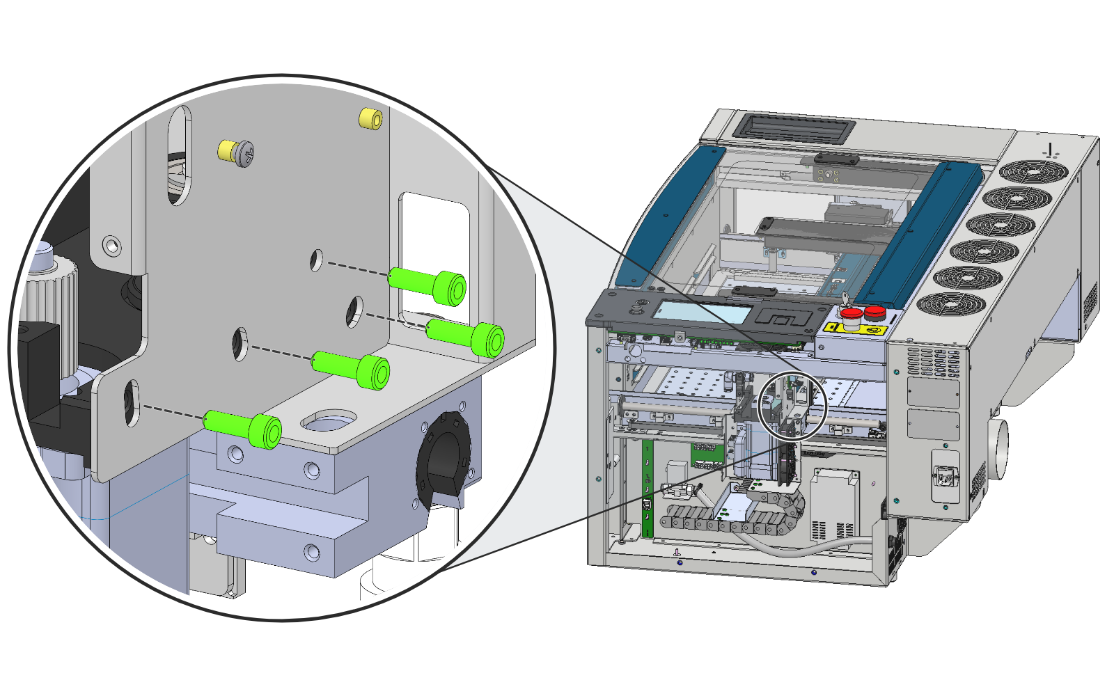
Install the Rear Screws
Repeat on the rear of the X-axis assembly: three screws until they stop but not snug, and the pivot screw snug.
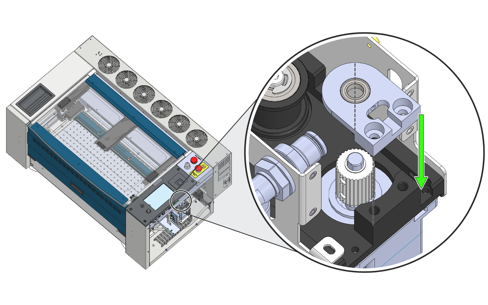
Install the End Bearing Support
Fit the end bearing support over the motor pulley shaft.
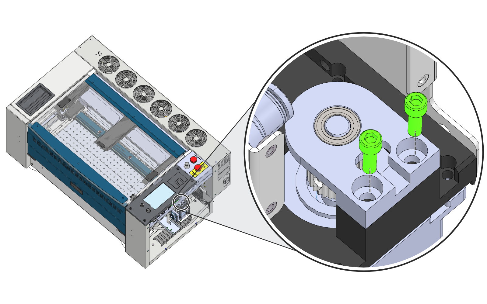
Install the Bearing Support Screws
Install the two screws (green) that secure the end bearing support.
Tighten the Nylon Screw
Gently tighten the nylon screw that secures the end bearing, only enough to keep the bearing outer race from turning.
Important: Overtightening the nylon screw will damage it.
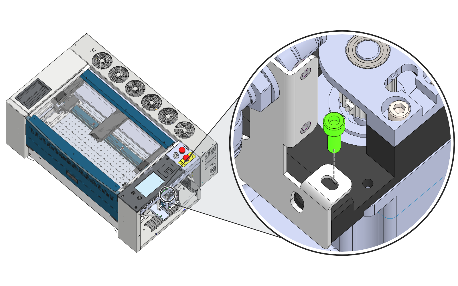
Install the Tilt Control Screw
Install the tilt control screw only until it bottoms out. Do not tighten it.
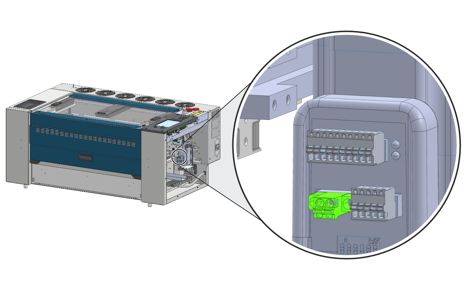
Connect the Power Connector
Plug the power connector into the X-axis motor and tighten its two small screws.
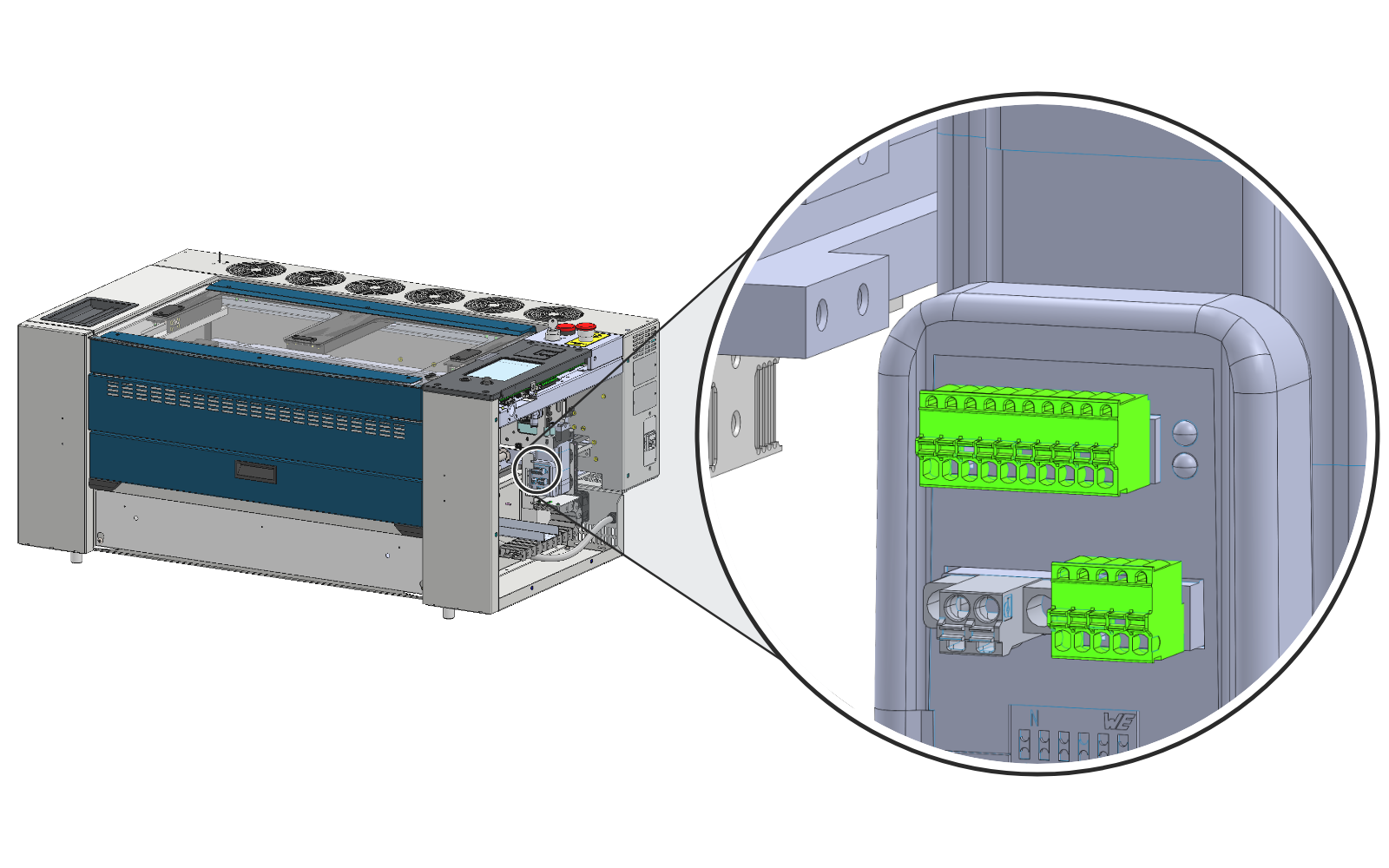
Connect the Remaining Connectors
Connect the two remaining electrical connectors to the motor.
Belt Tension and Tracking
Tension the X-Axis Belt
Tension the X-axis belt using the Epilog belt tensioning tool. See the X-Axis Belt Tensioning Guide for the full procedure.
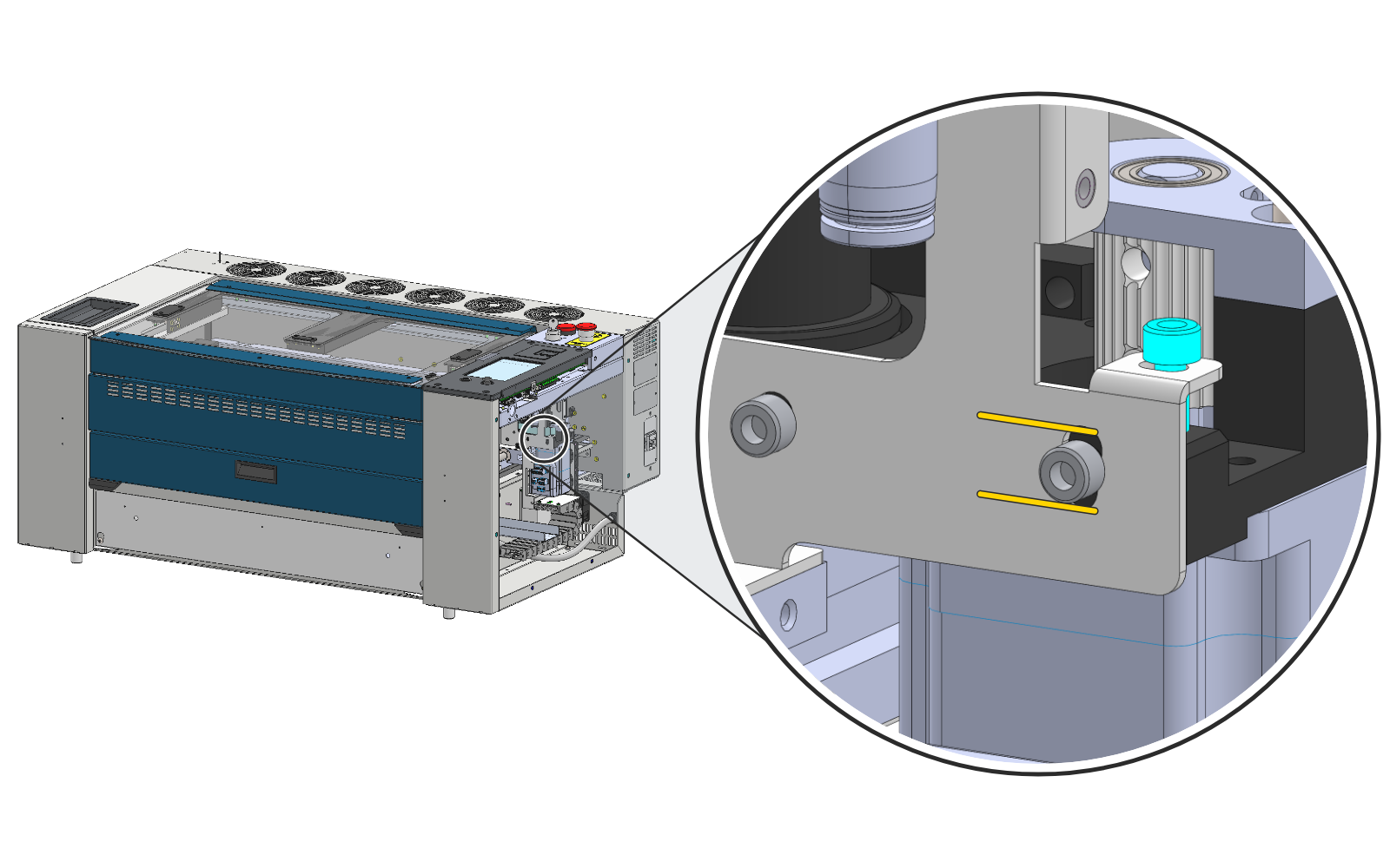
Align the Front Screw
Turn the tilt control screw (blue) to raise or lower the motor mount until the front screw lines up with the marks you made earlier. This gets the belt tracking close before you test it.
Run a Tracking Test
- Turn on the machine and let it start up fully.
- Create a 1-inch-tall box that spans the full width of the engraving area.
- Set the speed to 100% and the power to 0, or leave the top door open so the laser cannot fire.
- Start the job and watch how the belt runs on the X-axis motor pulley.
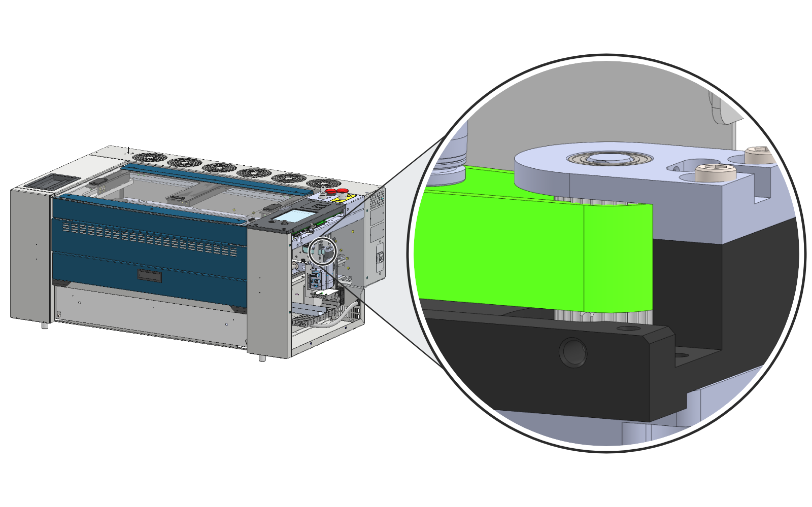
Set the Belt Tracking
The belt should run in the center of the motor pulley. It should never ride to one side for long, or its edge will wear and fail.
- Belt too high on the pulley: loosen the tilt control screw and press down on the motor mount.
- Belt too low on the pulley: tighten the tilt control screw.
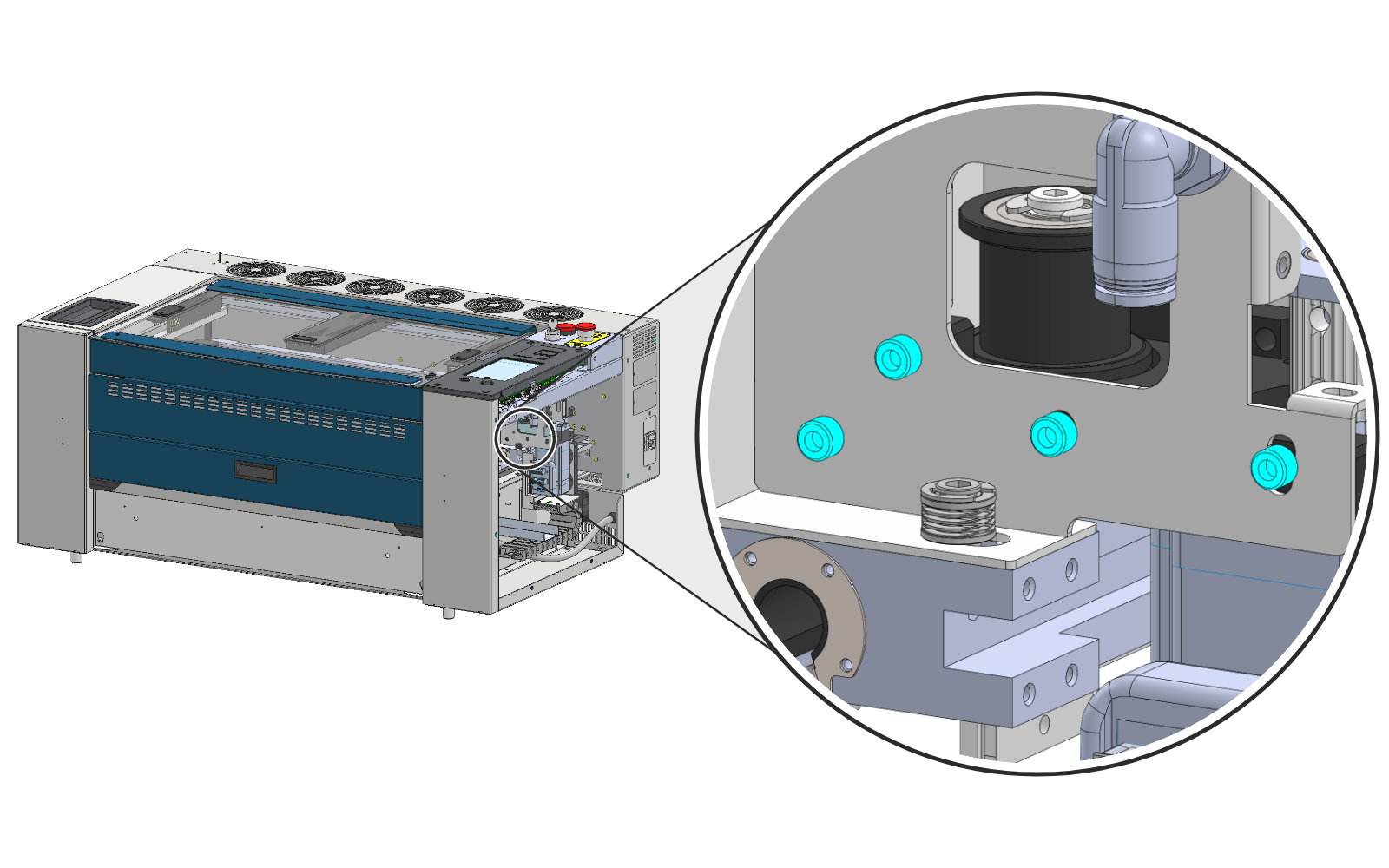
Tighten the Mount Screws
Once the tracking is set, tighten all four screws on the front of the X-axis assembly, then the four screws that secure the motor mount on the rear.
Recheck Tension and Install the Harness Cover
Double-check the X-axis belt tension and adjust it if needed. Slide the harness cover back in from the right-hand side so its slots engage the two screws, then tighten the screws.
Install the Side Panels
Install the left-hand side panel, then the right-hand side panel.