This guide covers replacing the x-axis PCB (x-axis interface board) on the Fusion Edge 12, 24 and 36 and the Fusion Pro 24 and 36. The board is mounted on the rear of the x-axis assembly.
Parts Required
- LC0806 – PCBA, X-Axis Interface
Tools / Materials Required
- 5/32" Allen Wrench
- Phillips Screwdriver
- Anti-Static Strap
Safety First: Ensure the engraver is completely powered off and the power cord is disconnected before removing any panels or touching internal components.
Using the Anti-Static Strap
An anti-static strap is required when working with any circuit board in the Fusion Edge and Fusion Pro. It keeps static electricity from building up and discharging into sensitive electronic components.
Put the Strap On
Take the anti-static strap out of its packaging, place it around your wrist and adjust it so it is tight but comfortable.
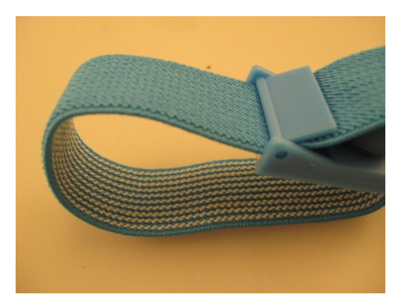
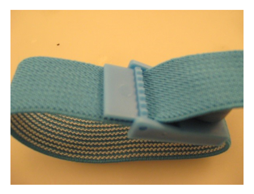
Adjustment Clamp
After sizing the strap, make sure the adjustment clamp is in the closed position.
Clamp Closed
Clamp Open
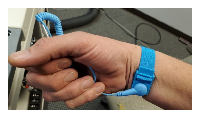
Check the Fit
The strap should be worn as shown, with the small metal plate on the inside of the strap touching your skin.
Attach the Clip
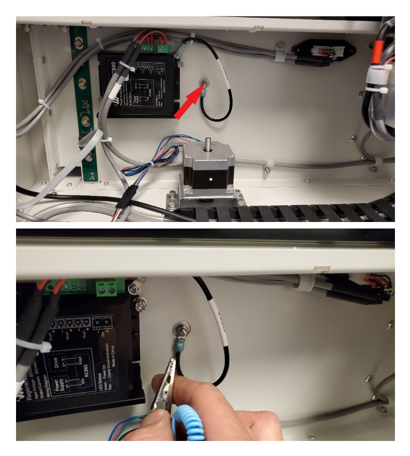
Attach the alligator clip to a bare metal surface in the engraver, such as a screw through-hole, a side panel tab or the chassis. The preferred spot is the chassis bolt for the regenerative clamp ground, behind the right panel (red arrow).
X-Axis PCB Removal
Turn Off Engraver
Turn off the engraver.
Disconnect from Power
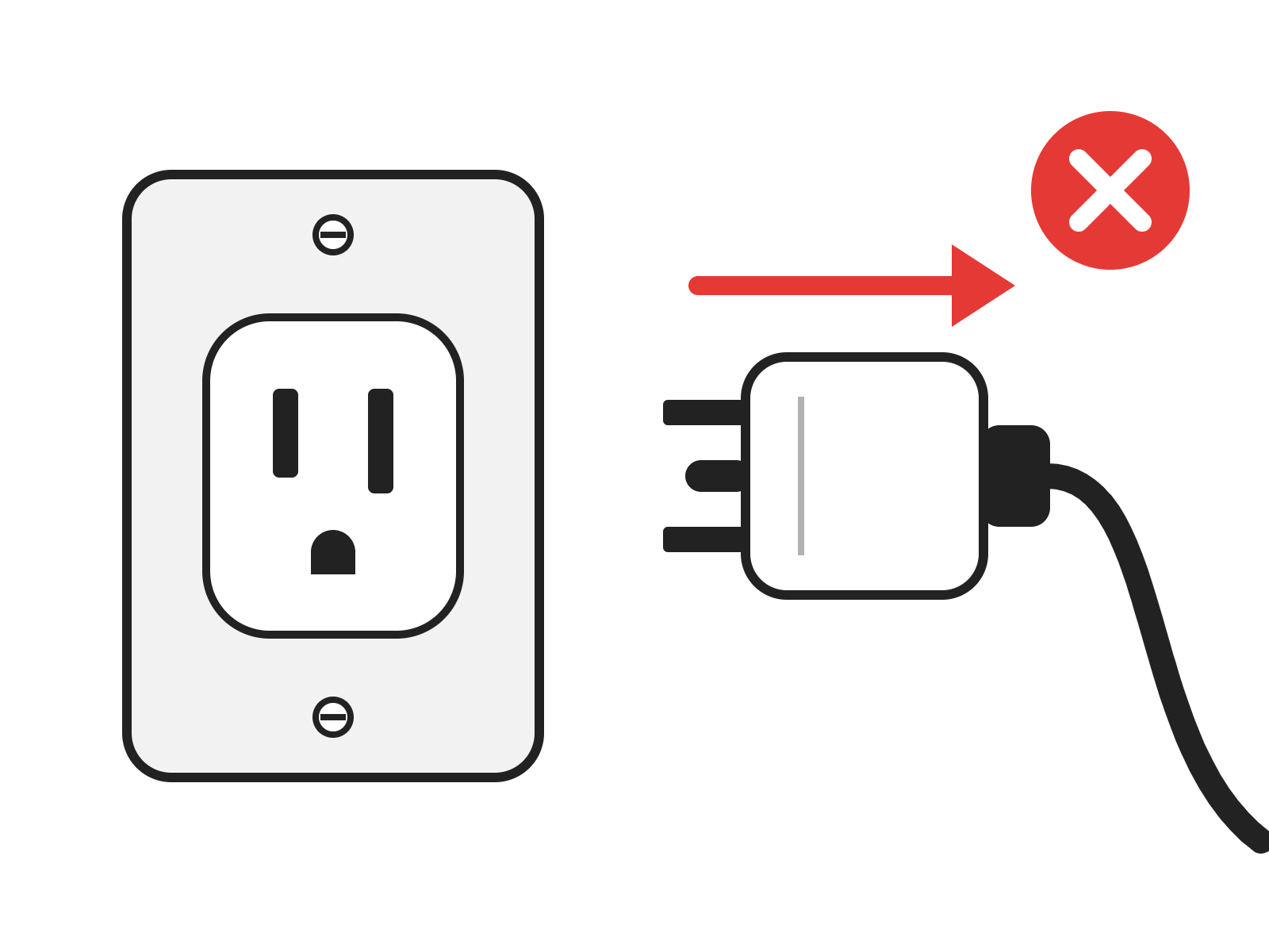
Unplug the engraver from its power source.
Remove Right Panel
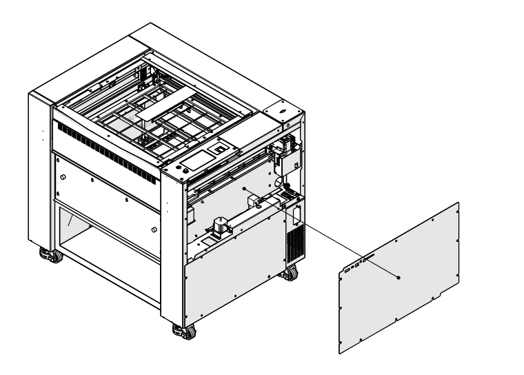
Remove the right panel of the engraver.
Center the X-Axis Assembly
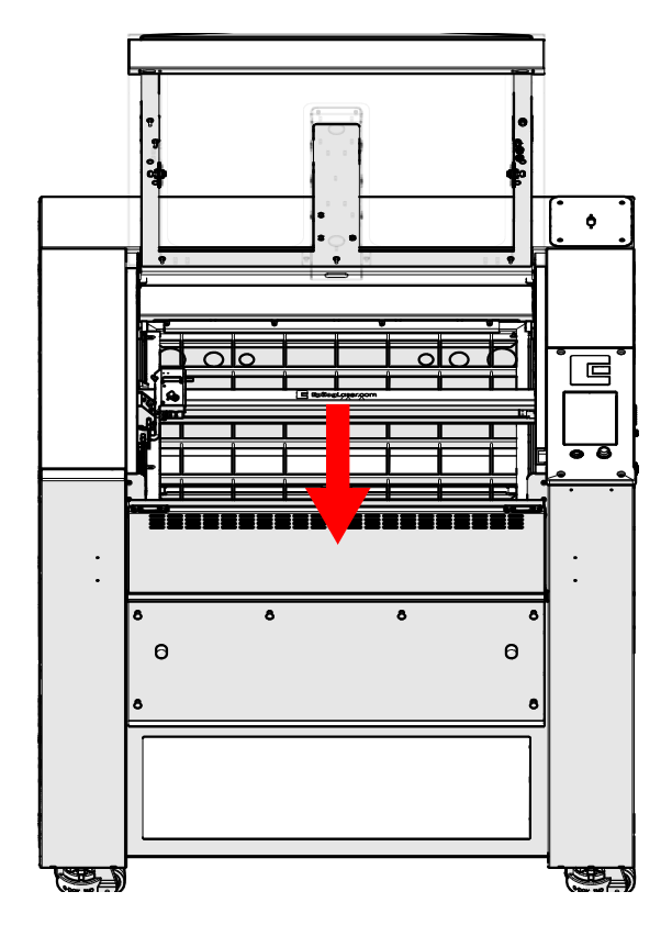
Manually move the x-axis assembly to the middle of the engraver.
Put On Anti-Static Strap
Put on the anti-static strap and clip it to bare metal as described above.
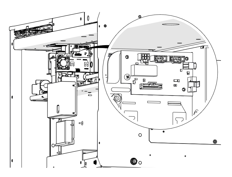
Locate the X-Axis PCB
Locate the x-axis PCB on the rear of the x-axis assembly.
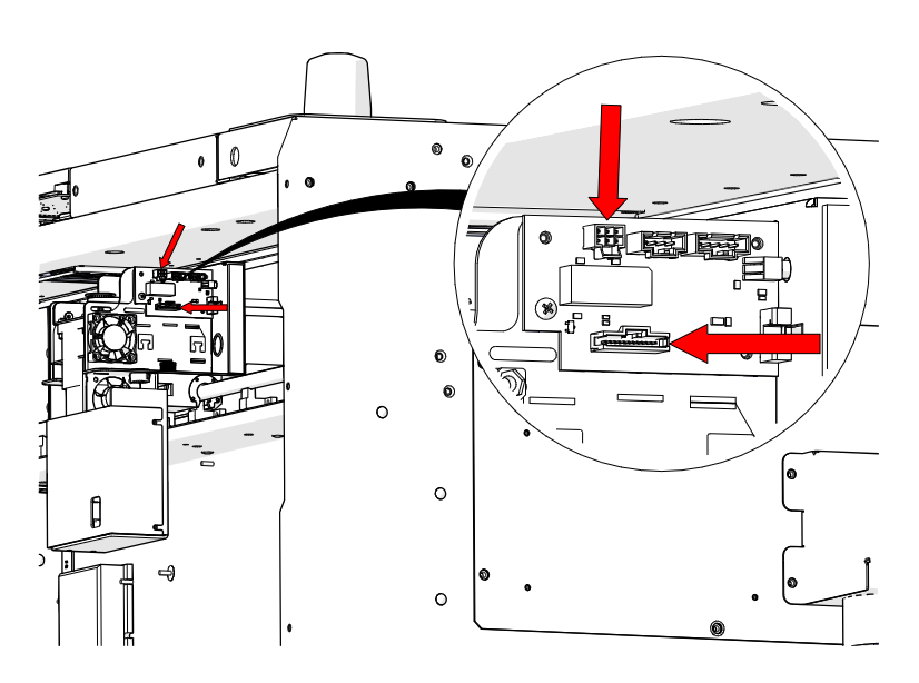
Disconnect the Cables
Disconnect the autofocus sensor harness and the flex cable from the x-axis PCB (red arrows).
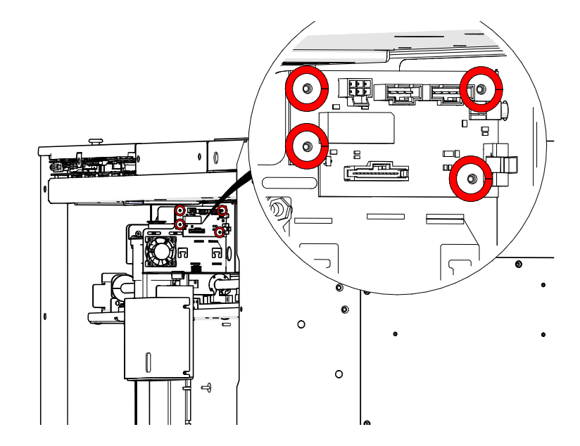
Remove PCB Screws
Loosen and remove the four Phillips screws that secure the x-axis PCB to the x-axis assembly (circled in red).
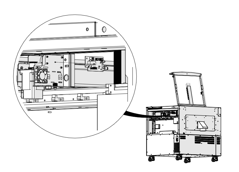
Remove the PCB
Remove the x-axis PCB.
X-Axis PCB Installation
Check the Anti-Static Strap
Make sure the anti-static strap is still on and clipped to bare metal.
Place the New PCB
Place the new LC0806 x-axis PCB in position.
Install PCB Screws
Install and tighten the four Phillips screws that secure the x-axis PCB to the x-axis assembly.
Connect the Cables
Connect the autofocus sensor harness and the flex cable to the x-axis PCB.
Install Right Panel
Install the right panel of the engraver.
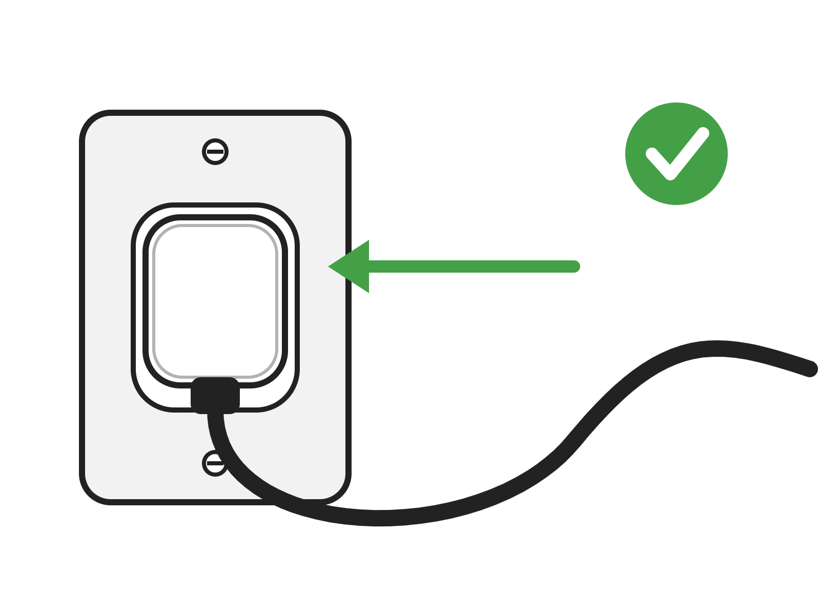
Power On
Reconnect the engraver to power and turn it on.