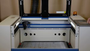
This guide covers replacing the complete x-axis assembly on the Fusion Maker, Fusion Edge and Fusion Pro 24 and 36. The x-axis assembly contains circuit boards, cameras and a motor, so after installation the carriage camera (Pro models) and the engraver peripherals are updated from the display.
Parts Required
- X-axis assembly for your engraver model (see the part number table below)
Tools / Materials Required
- 5/32" Allen Wrench
- Phillips Screwdriver
- Anti-Static Strap
Safety First: Ensure the engraver is completely powered off and the power cord is disconnected before removing any panels or touching internal components.
Part Numbers
X-Axis Assembly Part Numbers
| Model | Part Number | Description |
|---|---|---|
| Maker 12 | LC1060-TS | Assy, X-Axis Rail, 24×12, Maker, TS |
| Edge 12 CO2 | LC0485-TS | Assy, X-Axis Rail, 24×12, CO2, TS |
| Edge 12 Fiber | LC0486-TS | Assy, X-Axis Rail, 24×12, Fiber, TS |
| Edge 24 CO2 | LC0970-TS | Assy, X-Axis Rail, 24×24, Edge, CO2, TS |
| Edge 24 Fiber | LC0971-TS | Assy, X-Axis Rail, 24×24, Pro, Fiber, TS |
| Pro 24 CO2 | LC1034-TS | Assy, X-Axis Rail, 24×24, Pro, CO2, TS |
| Pro 24 Dual | LC1035-TS | Assy, X-Axis Rail, 24×24, Pro, Dual, TS |
| Edge 36 CO2 | LC1056-TS | Assy, X-Axis Rail, 36×24, Edge, CO2, TS |
| Pro 36 CO2 | LC1057-TS | Assy, X-Axis Rail, 36×24, Pro, CO2, TS |
| Pro 36 Dual | LC1058-TS | Assy, X-Axis Rail, 36×24, Pro, Dual, TS |
Fusion Maker: The Fusion Maker does not have the x-axis drive board used in this procedure. Skip the steps that mention the x-axis drive board.
X-Axis Assembly Removal
Turn Off Engraver
Turn off the engraver.
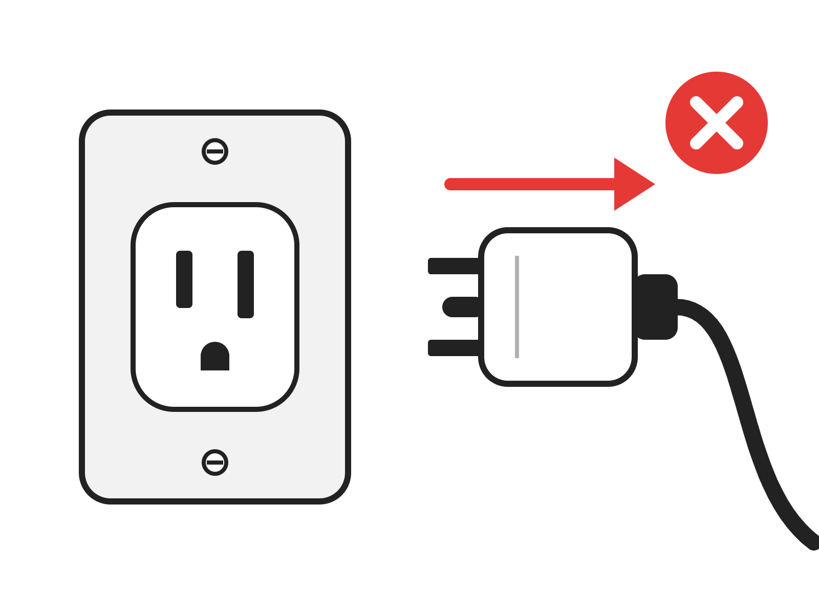
Disconnect from Power
Unplug the engraver from its power source.
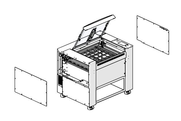
Remove Side Panels
Remove the left and right panels of the engraver.
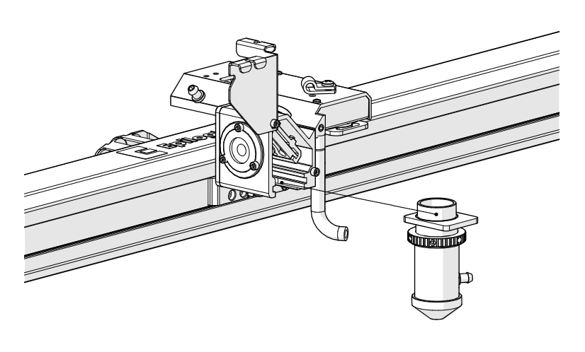
Remove Lens Tube
Loosen and remove the lens tube assembly from the x-axis assembly.
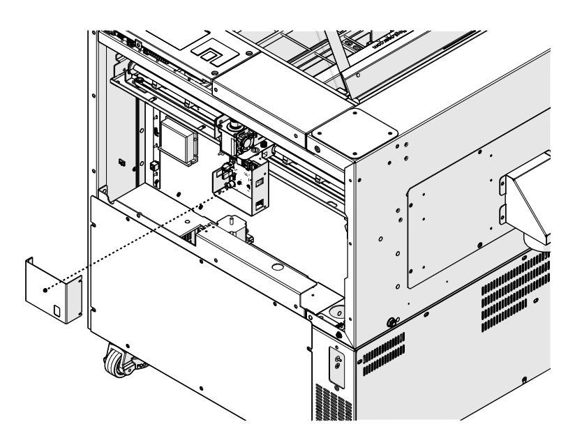
Remove Drive Board Cover
Remove the x-axis drive board cover.
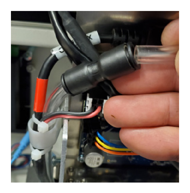
Disconnect Air Assist
Disconnect the air assist tubing from the right side of the x-axis assembly.
Note: The tubing is held by a coupler. Press the tubing into the coupler, then hold the retaining ring against the coupler and pull the tubing out.
Put On Anti-Static Strap
Place the anti-static strap around your wrist and attach the clamp to bare metal on the engraver.
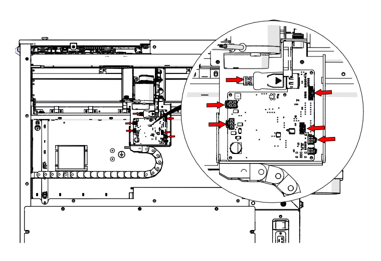
Disconnect Drive Board
Disconnect the six electrical connectors from the x-axis drive board (red arrows).
Remove Bracket Screws
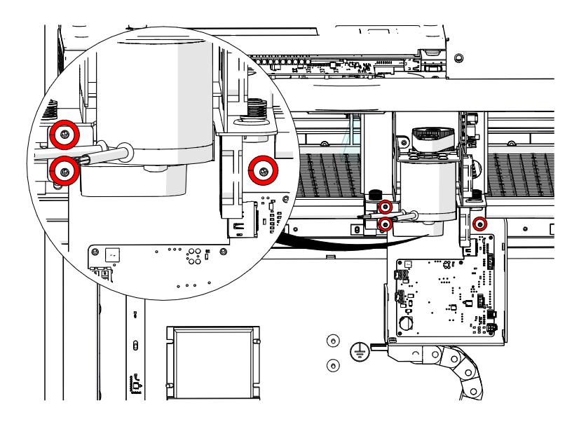
Loosen and remove the three Phillips screws that secure the x-axis drive board mounting bracket to the x-axis assembly (circled in red).
Remove the Drive Board
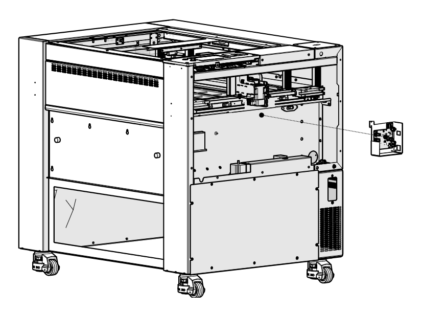
Remove the x-axis drive board and housing.
Disconnect the Bellows
Disconnect the bellows on the left and right sides of the engraver.
Remove X-Axis Fasteners
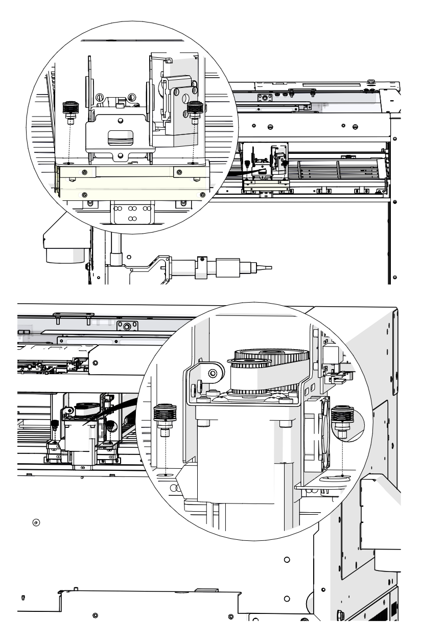
Remove the four fasteners that secure the x-axis assembly to the y-axis bearings: two on the right side and two on the left side.
Lift the X-Axis Assembly
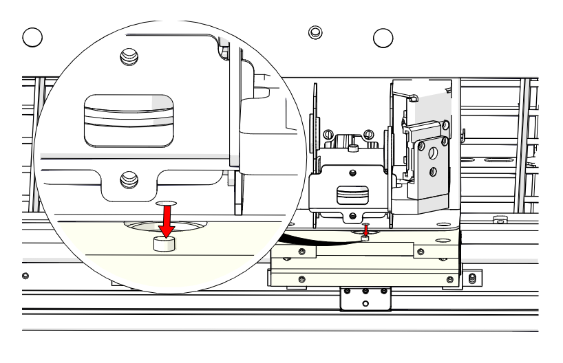
Gently lift the x-axis assembly off the locator pins on the y-axis bearing blocks.
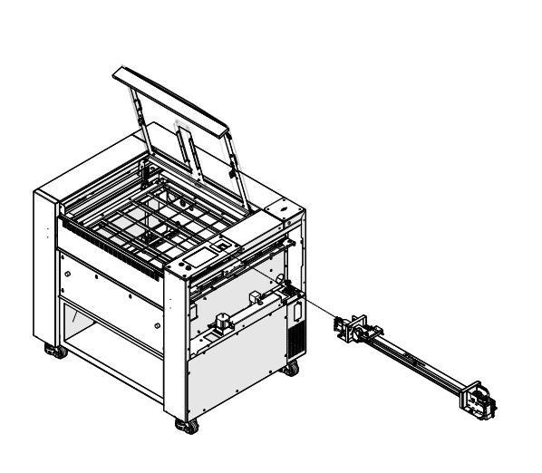
Remove the X-Axis Assembly
Slide the x-axis assembly out of the cabinet through the right side of the engraver.
X-Axis Assembly Installation
Install the New Assembly
Slide the new x-axis assembly into the cabinet through the right side of the engraver.
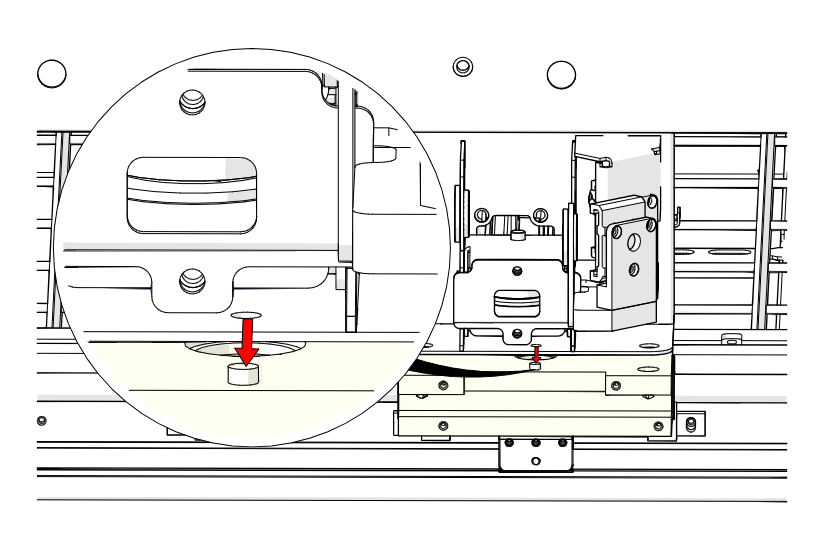
Seat on the Locator Pins
Set the x-axis assembly on the y-axis bearing blocks so it sits on the locator pins.
Install X-Axis Fasteners
Install and tighten the four fasteners that secure the x-axis assembly to the y-axis bearings.
Reconnect the Bellows
Reconnect the bellows on the left and right sides of the engraver.
Position the Drive Board
Place the x-axis drive board and housing in position.
Install Bracket Screws
Install and tighten the three Phillips screws that secure the drive board mounting bracket to the x-axis assembly.
Connect Drive Board
Connect the six electrical harnesses to the x-axis drive board.
Connect Air Assist
Connect the air assist tubing to the right side of the x-axis assembly.
Install Drive Board Cover
Install the x-axis drive board cover.
Install Lens Tube
Install the lens tube assembly in the x-axis assembly.
Install Side Panels
Install the left and right panels of the engraver.
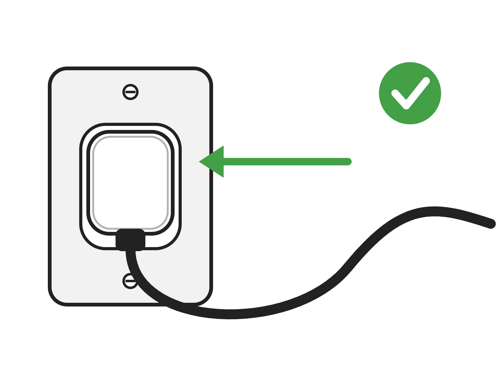
Power On
Reconnect the engraver to power and turn it on.
Updating the Carriage Camera (Pro Models Only)

Open the Settings Menu
On the display, press the gear icon to open the Settings menu.
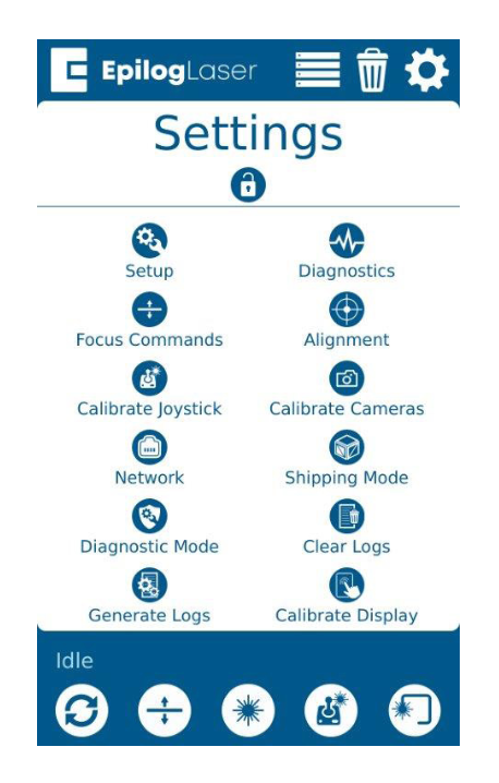
Open Advanced Settings
Press and hold the word Settings to open the Advanced Settings menu.
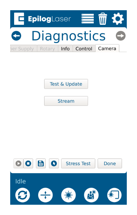
Open the Camera Tab
Open Diagnostics, scroll to the Camera tab and press Test & Update.
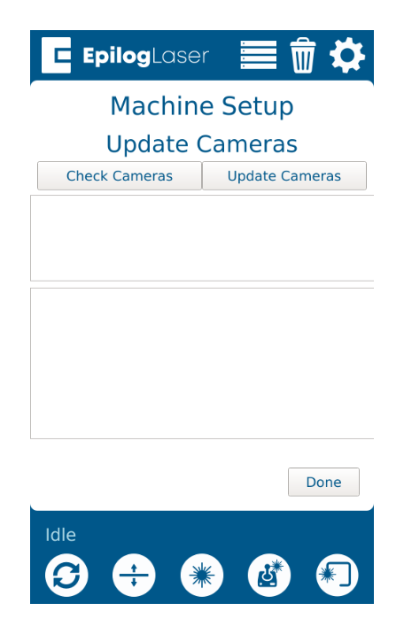
Update the Camera
Press Update Cameras.
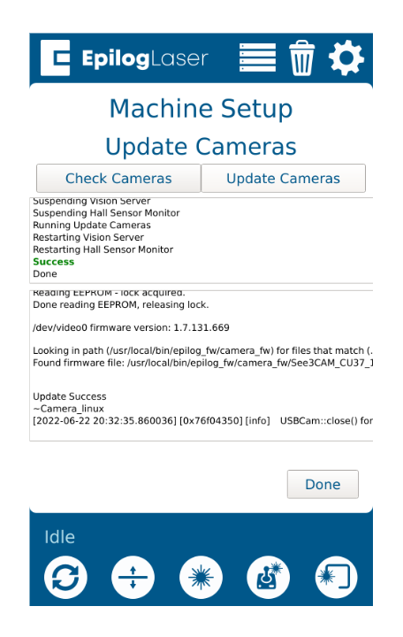
Wait for Success
Let the engraver finish the update. A success message appears when it is done.
Note: In some cases the focus calibration and camera calibration must also be completed. See the Fusion Edge / Pro user manual.
Updating the Peripherals
Open the Settings Menu
On the display, press the gear icon in the upper right corner to open the Settings menu.
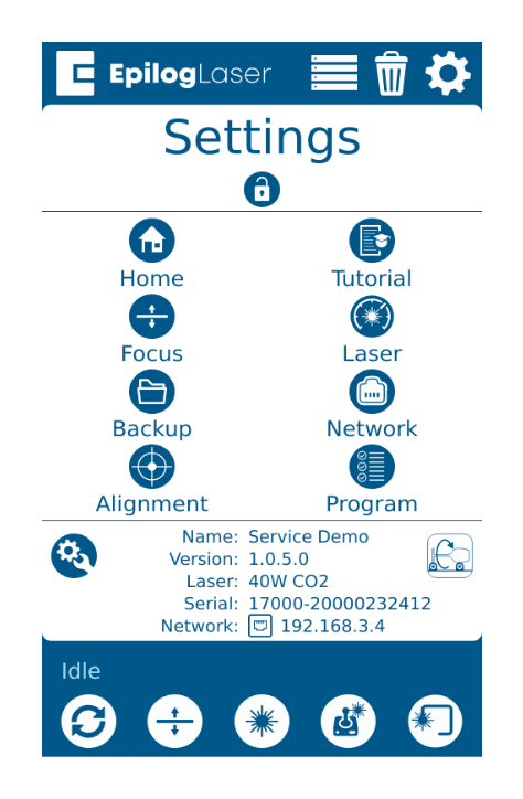
Open Peripheral Update
Press Program to open the Peripheral Update menu.
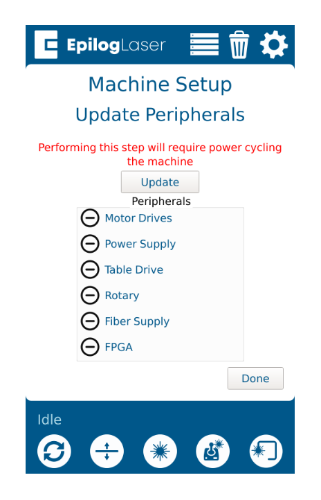
Update Motor Drives and FPGA
Select Motor Drives and FPGA, then press Update.
Important: Do not power off the engraver during the update. It is normal for the display to turn off while the update runs. When the update has been applied, the engraver prompts you to restart.
Restart When Prompted
When the engraver prompts you to restart, power cycle the engraver.