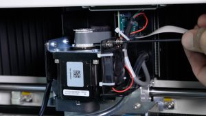
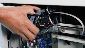
This guide covers replacing the x-axis reducer drive on the Fusion Edge 12, 24 and 36 and the Fusion Pro 24 and 36. The x-axis assembly is removed from the engraver to reach the reducer, then the x-axis belt is re-tensioned using the motor’s RMS current reading.
Parts Required
- LC0238 – X-Axis Reducer Assembly, 12, 24, 36
Tools Required
- 2.5 mm Allen Wrench
- 5/32" Allen Wrench
- 7/64" Allen Wrench
- Phillips Screwdriver
Safety First: Ensure the engraver is completely powered off and the power cord is disconnected before removing any panels or touching internal components.
Remove the X-Axis Assembly
Turn Off Engraver
Turn off the engraver.
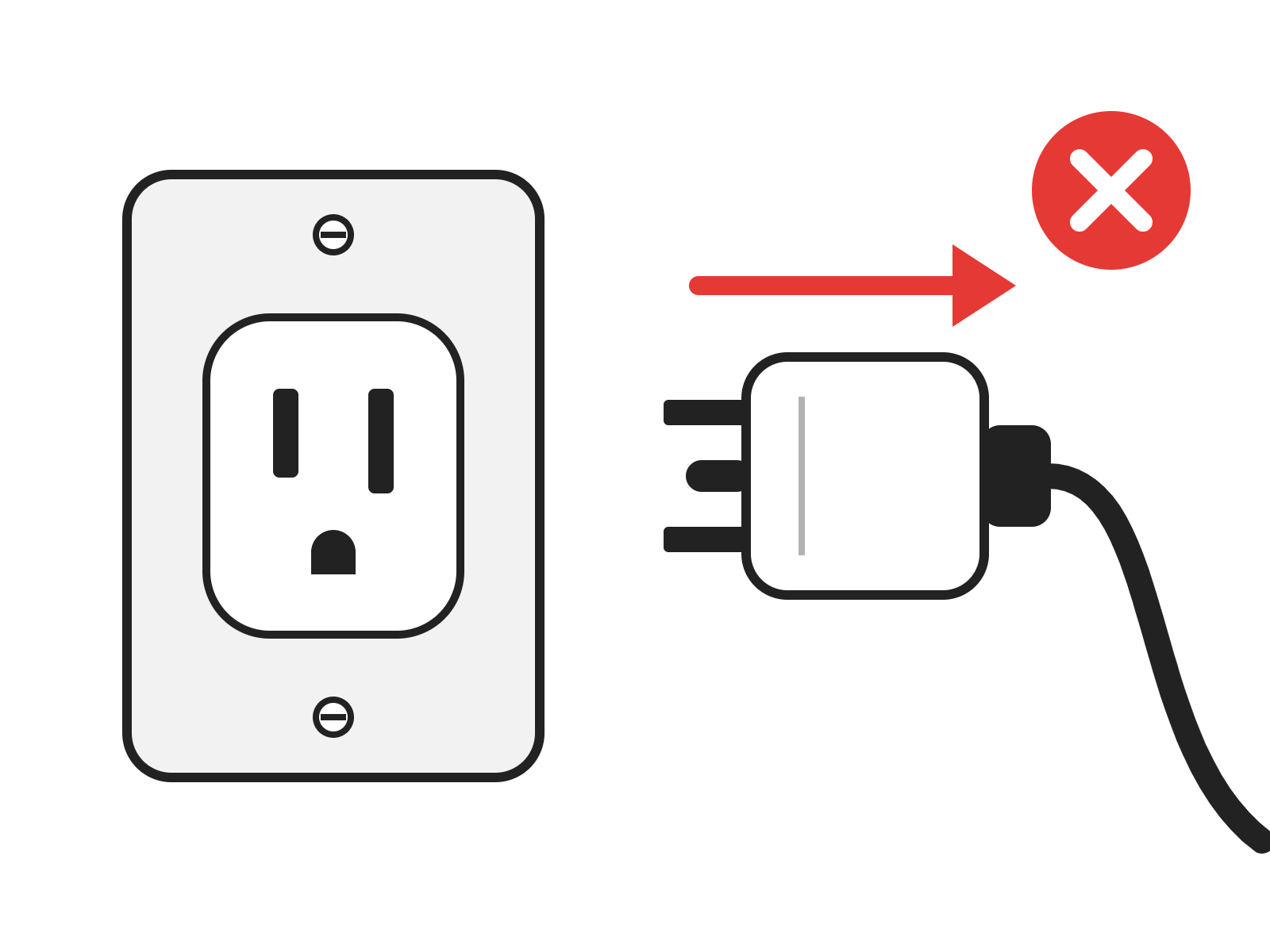
Disconnect from Power
Unplug the engraver from its power source.
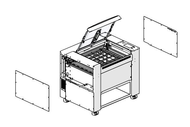
Remove Side Panels
Remove the left and right panels of the engraver.
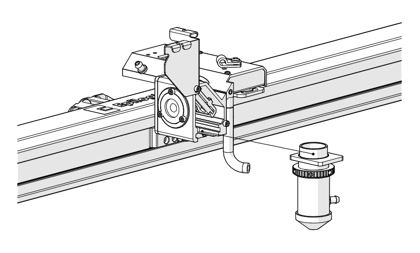
Remove Lens Tube
Loosen and remove the lens tube assembly from the x-axis assembly.
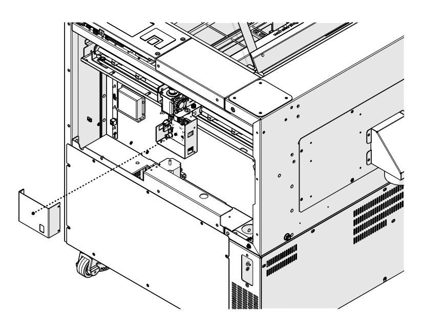
Remove Drive Board Cover
Remove the x-axis drive board cover.
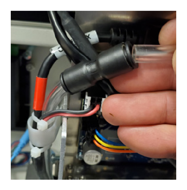
Disconnect Air Assist
Disconnect the air assist tubing from the right side of the x-axis assembly.
Note: The tubing is held by a coupler. Press the tubing into the coupler, then hold the retaining ring against the coupler and pull the tubing out.
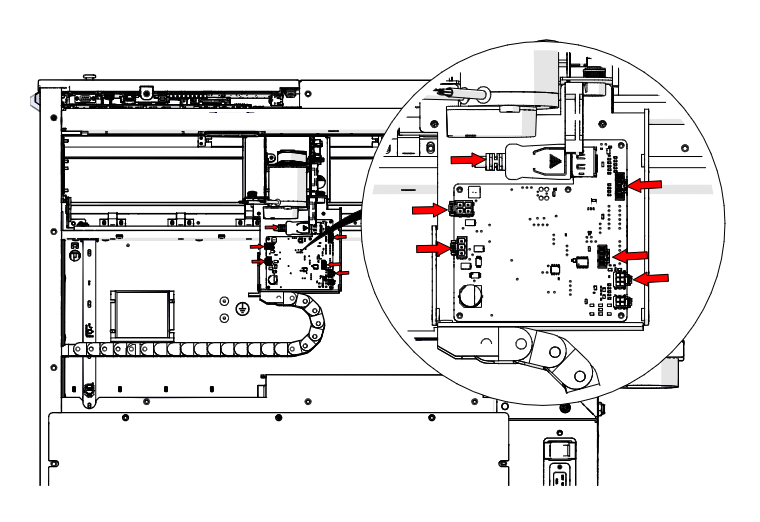
Disconnect Drive Board
Disconnect the six electrical connectors from the x-axis drive board (red arrows).
Remove Bracket Screws
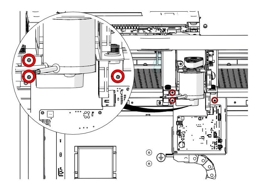
Loosen and remove the three Phillips screws that secure the x-axis drive board mounting bracket to the x-axis assembly (circled in red).
Remove the Drive Board
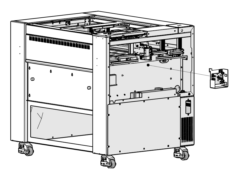
Remove the x-axis drive board and housing.
Disconnect the Bellows
Disconnect the bellows on the left and right sides of the engraver.
Remove X-Axis Fasteners
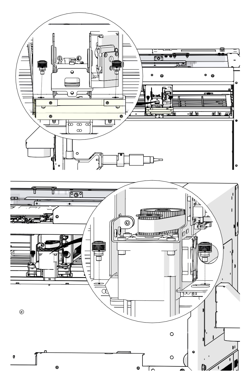
Remove the four fasteners that secure the x-axis assembly to the y-axis bearings: two on the right side and two on the left side.
Lift the X-Axis Assembly
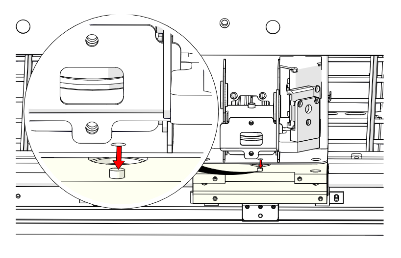
Gently lift the x-axis assembly off the locator pins on the y-axis bearing blocks.
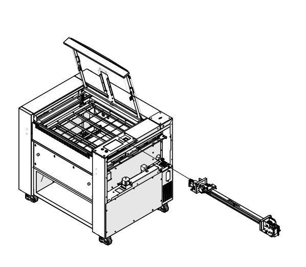
Remove the X-Axis Assembly
Slide the x-axis assembly out of the cabinet through the right side of the engraver.
Reducer Drive Removal
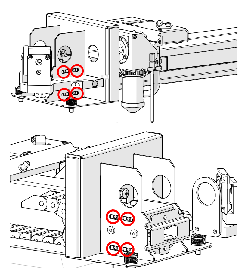
Loosen Idler Mounting Screws
Loosen, but do not remove, the eight 7/64" Allen screws on the x-axis idler assembly.
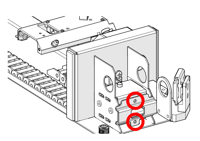
Loosen Tensioner Screws
Loosen, but do not remove, the two 7/64" tensioner screws on the idler assembly body.
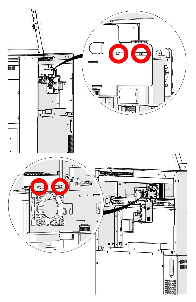
Loosen Motor Screws
Loosen, but do not remove, the four 7/64" Allen screws that secure the x-axis motor to the x-axis assembly (circled in red).
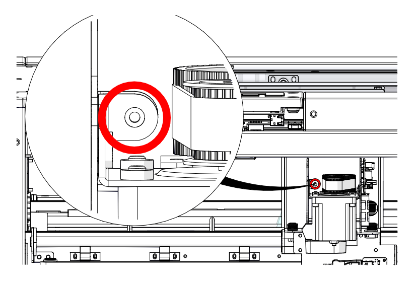
Loosen Reducer Belt Tensioner
Loosen the 7/64" Allen screw on the reducer drive belt tensioner (circled in red).
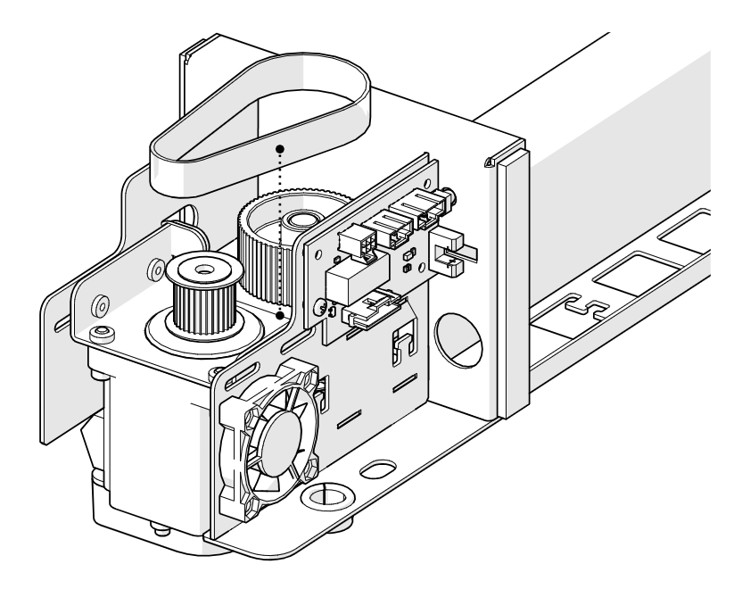
Remove the Reducer Belt
Remove the reducer drive belt.
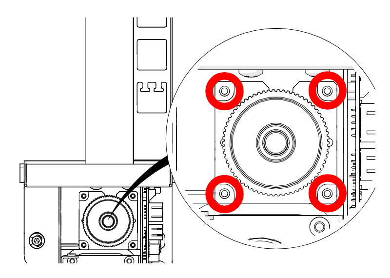
Remove Reducer Screws
Loosen and remove the four 2.5 mm Allen screws on the reducer drive assembly (circled in red).
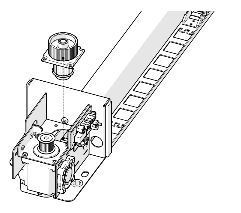
Remove the Reducer Drive
Remove the reducer drive assembly.
Reducer Drive Installation
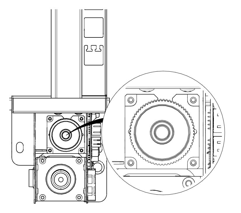
Install the New Reducer Drive
Install the new LC0238 reducer drive assembly in the x-axis assembly so the x-axis belt wraps around the bottom pulley. The notch on the reducer baseplate must face away from the x-axis motor.
Install Reducer Screws
Install and tighten the four 2.5 mm Allen screws on the reducer drive assembly.
Install the Reducer Belt
Install the reducer drive belt.
Tension the Reducer Belt
Tighten the 7/64" Allen screw on the reducer drive belt tensioner until the slack is removed from the reducer belt.
Tighten Motor Screws
Tighten the four 7/64" Allen screws that secure the x-axis motor to the x-axis assembly.
Install the X-Axis Assembly
Install the X-Axis Assembly
Slide the x-axis assembly into the cabinet through the right side of the engraver.
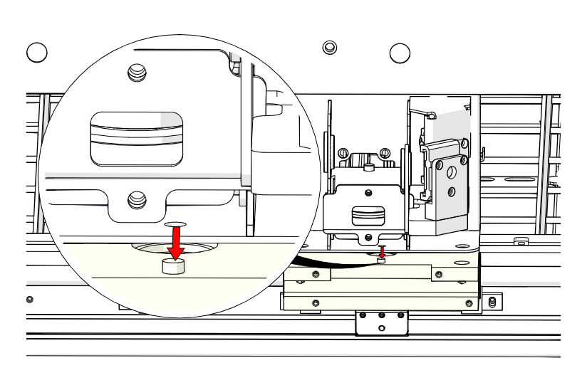
Seat on the Locator Pins
Set the x-axis assembly on the y-axis bearing blocks so it sits on the locator pins.
Install X-Axis Fasteners
Install and tighten the four fasteners that secure the x-axis assembly to the y-axis bearings.
Reconnect the Bellows
Reconnect the bellows on the left and right sides of the engraver.
Position the Drive Board
Place the x-axis drive board and housing in position.
Install Bracket Screws
Install and tighten the three Phillips screws that secure the drive board mounting bracket to the x-axis assembly.
Connect Drive Board
Connect the six electrical harnesses to the x-axis drive board.
Connect Air Assist
Connect the air assist tubing to the right side of the x-axis assembly.
Install Drive Board Cover
Install the x-axis drive board cover.
Install Lens Tube
Install the lens tube assembly in the x-axis assembly.
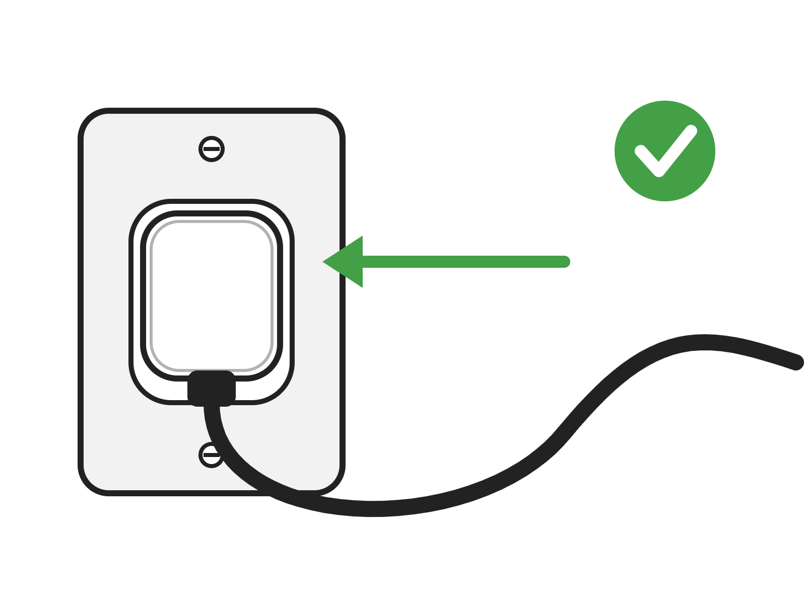
Power On
Reconnect the engraver to power and turn it on. Leave the side panels off for belt tensioning.
Tensioning the X-Axis Belt
Create a Test Box
In your preferred illustration program, create a black raster box on the artboard that is:
- Edge / Pro 12 and 24: 22" (560 mm) wide
- Edge / Pro 36: 34" (860 mm) wide
- Roughly 4" (100 mm) tall
Print the Job
Print the job with the speed set to 100%.
Note: Power does not matter here, as the engraver runs with the lid open for this procedure.
Start the Job
Send the job to the engraver and start it.

Open the Settings Menu
On the display, press the gear icon in the upper right corner to open the Settings menu.
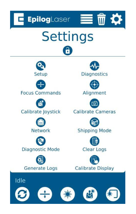
Open Advanced Settings
Press and hold the word Settings to open the Advanced Settings menu.
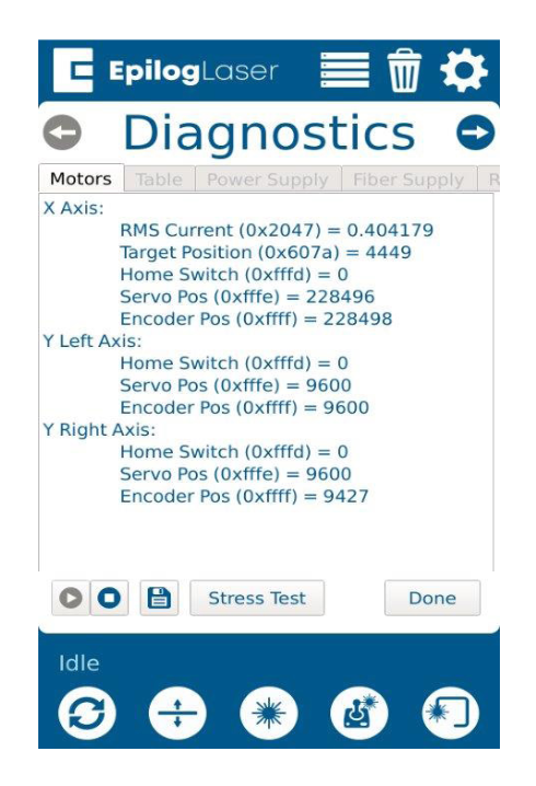
Find the X-Axis RMS Current
Open the Diagnostics menu and find the RMS Current reading for the X-Axis motor/drive.
Adjust to 4.0 – 5.1 A
While the job runs, the x-axis motor RMS current should be between 4.0 and 5.1 A, depending on the engraver model.
- If the current is lower, increase belt tension by tightening the two 7/64" tensioner screws on the x-axis idler assembly.
- If the current is higher, decrease belt tension by loosening the two 7/64" tensioner screws.
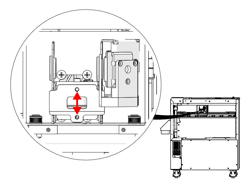
Check Belt Tracking
With the belt tensioned, check that the x-axis belt stays as centered as possible on the idler pulley while in motion.
Center the Belt
If the belt rides against the idler pulley flange, make equal but opposite adjustments to the two 7/64" tensioner screws. Repeat until the belt stays centered on the pulley in motion.
- Belt too high: tighten the top screw 1/4 turn and loosen the bottom screw 1/4 turn.
- Belt too low: loosen the top screw 1/4 turn and tighten the bottom screw 1/4 turn.
Tighten Idler Mounting Screws
Once the belt is centered and the RMS current is in range, tighten the eight 7/64" idler mounting screws on the left side of the x-axis assembly.
Install Side Panels
Install the left and right panels of the engraver.