Estimated time: 30-45 minutes • Skill: Intermediate
This guide walks you through replacing the camera cable on a G100 laser system. Only perform this procedure if the camera cable has failed and replacement is absolutely necessary. Several steps require removing panels and tilting the machine on its back which requires two people. Use caution and follow all safety notes carefully.
Removal
-
Power on the machine.
Allow the machine to complete startup normally.
![]()
Figure 1. Powering on the G100 laser. -
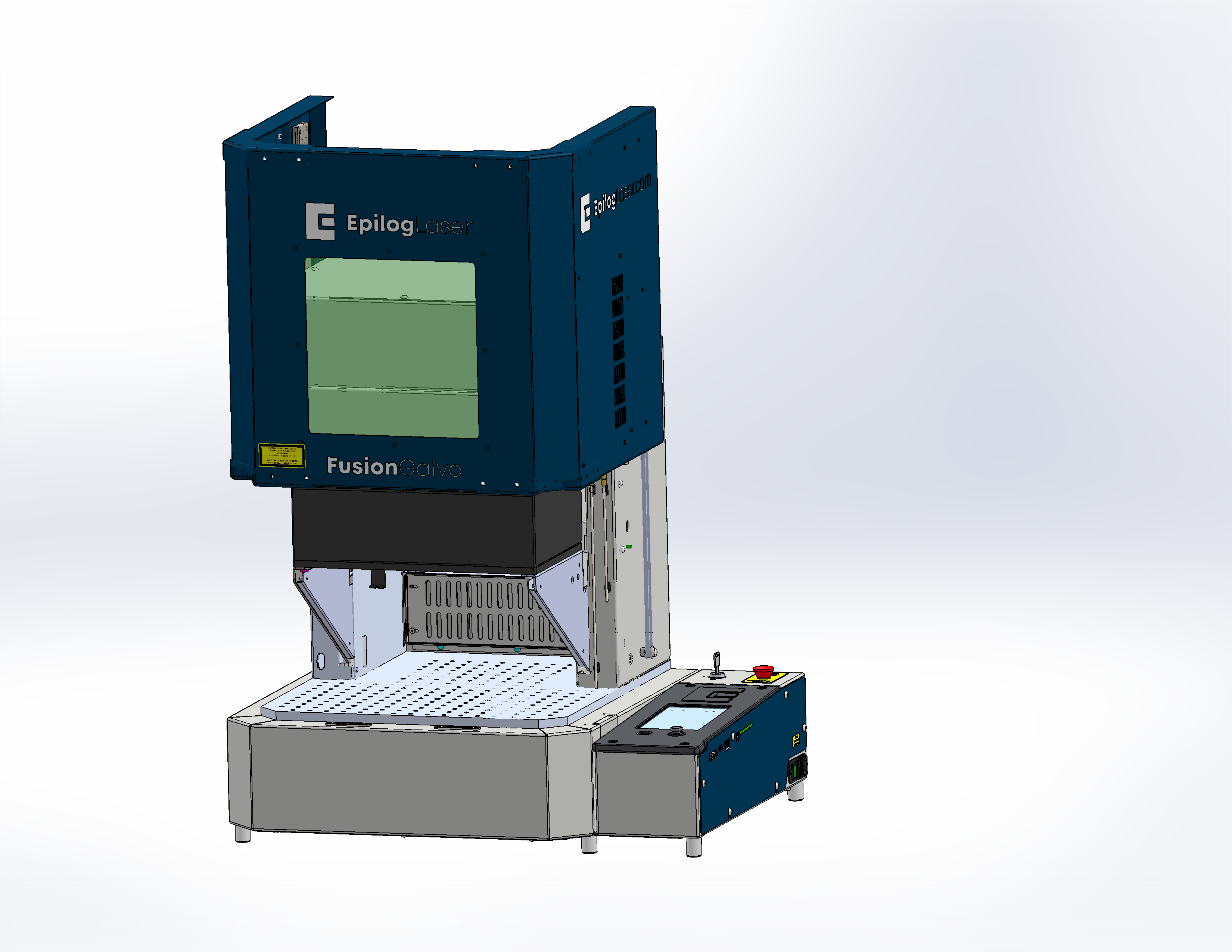
Raise the galvo platform.
This provides better access for later steps.
![]()
Figure 2. Raising the galvo platform. -
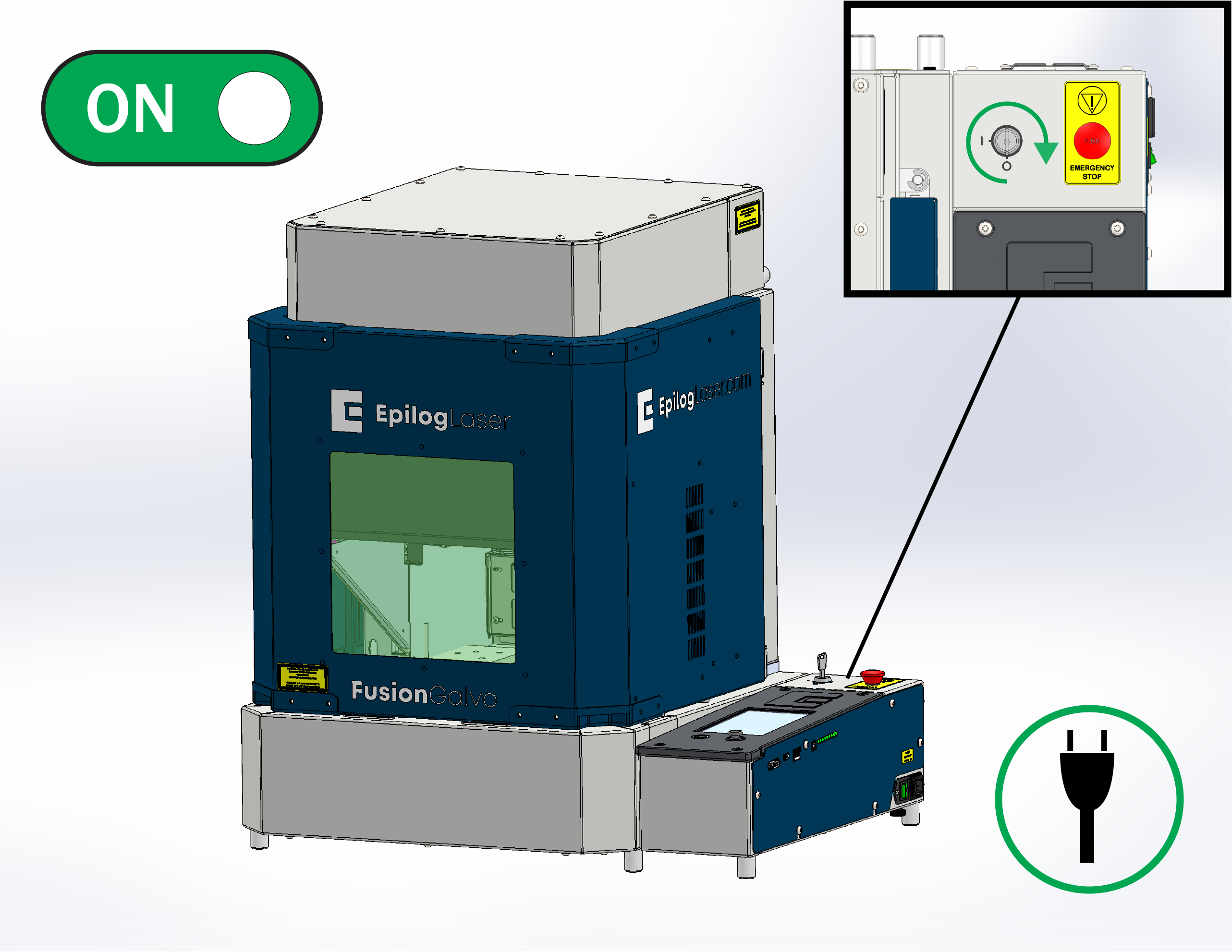
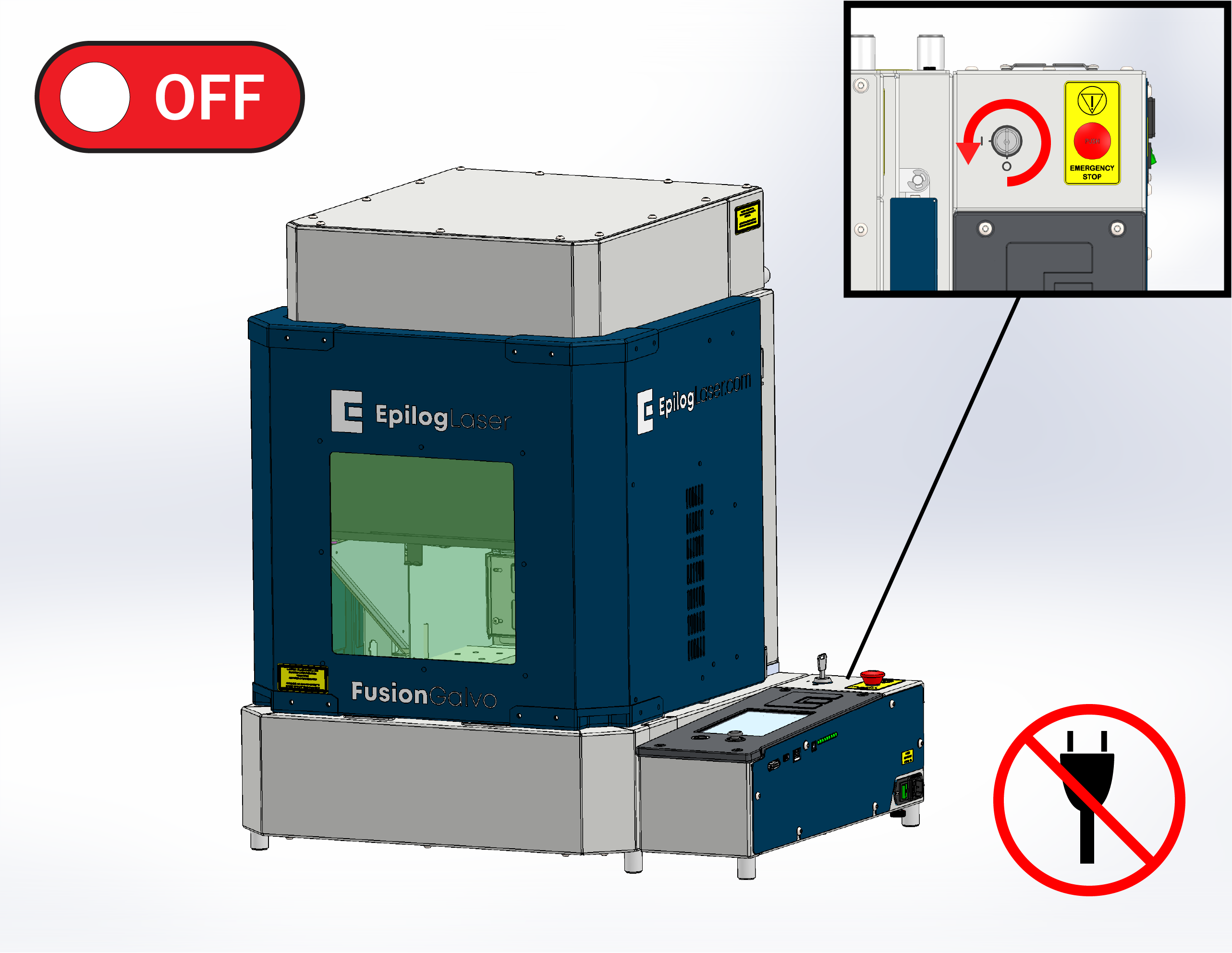
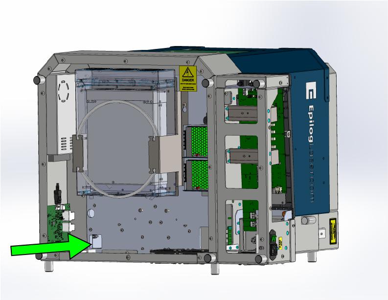
Power off and disconnect the machine.
Turn the system off completely and disconnect the power cable before removing any panels.
![]()
Figure 3. Powering down the machine. -
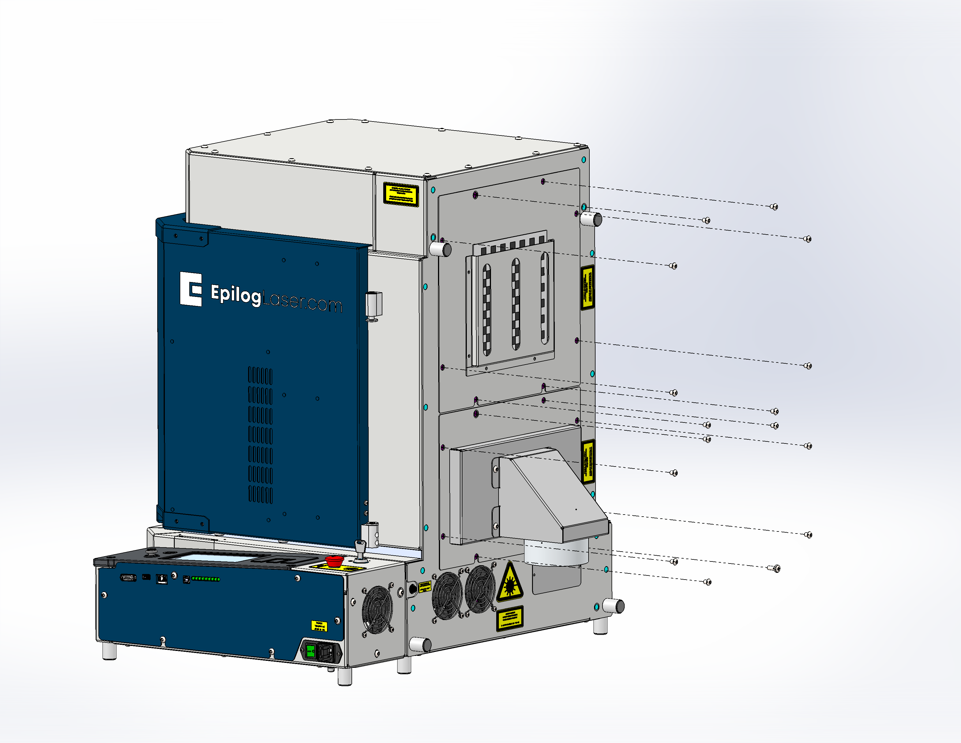
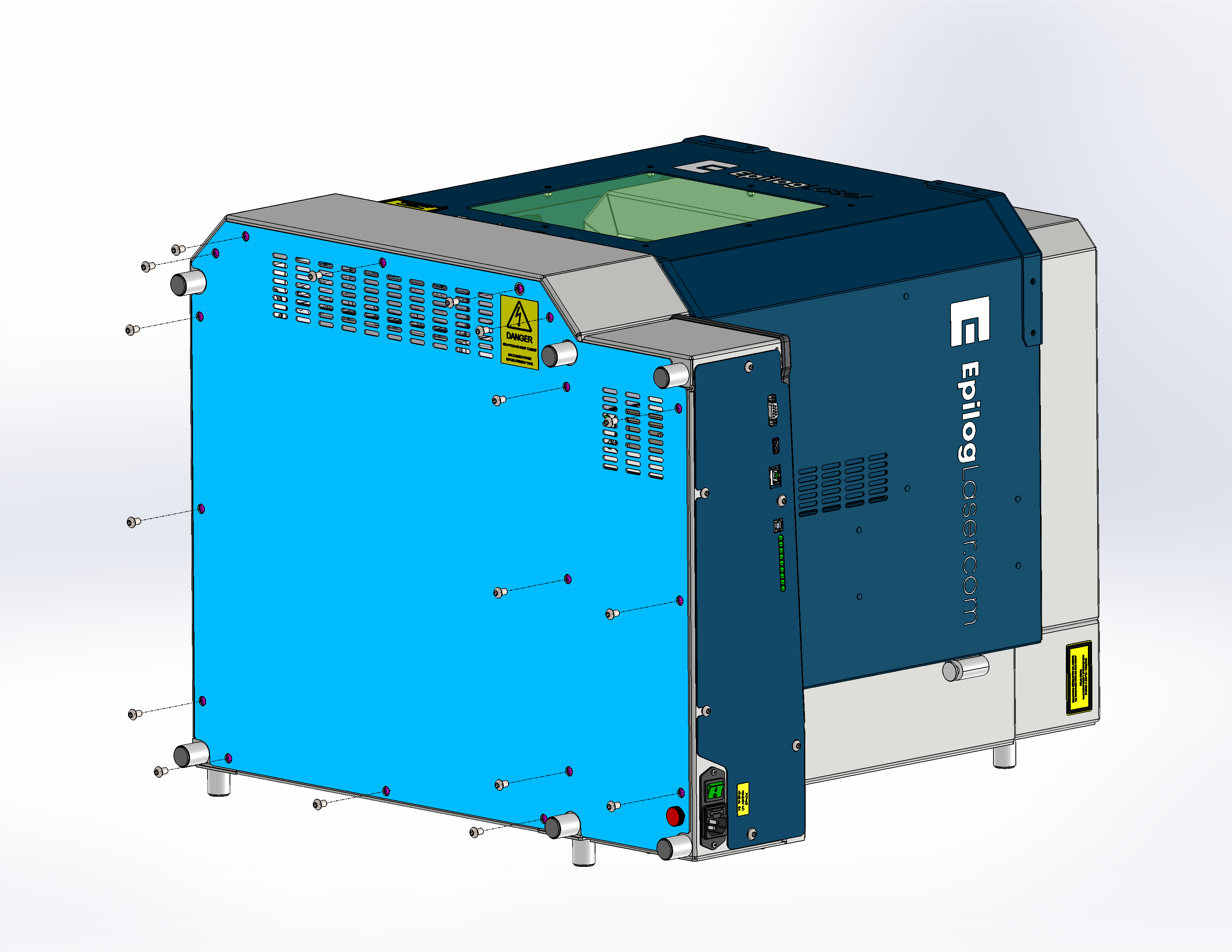
Remove the rear panels.
![]()
Figure 4a. Rear panel screws removed. ![]()
Figure 4b. Rear panels removed. -
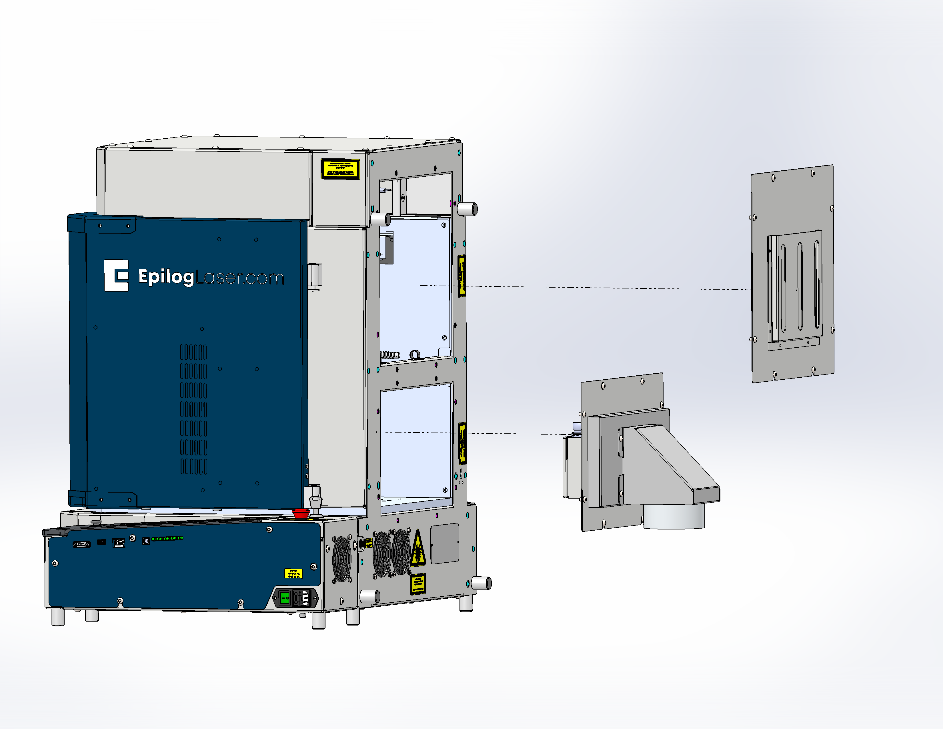
Remove the two inner side panels.
![]()
Figure 5a. First inner side panel removed. ![]()
Figure 5b. Second inner side panel removed. -
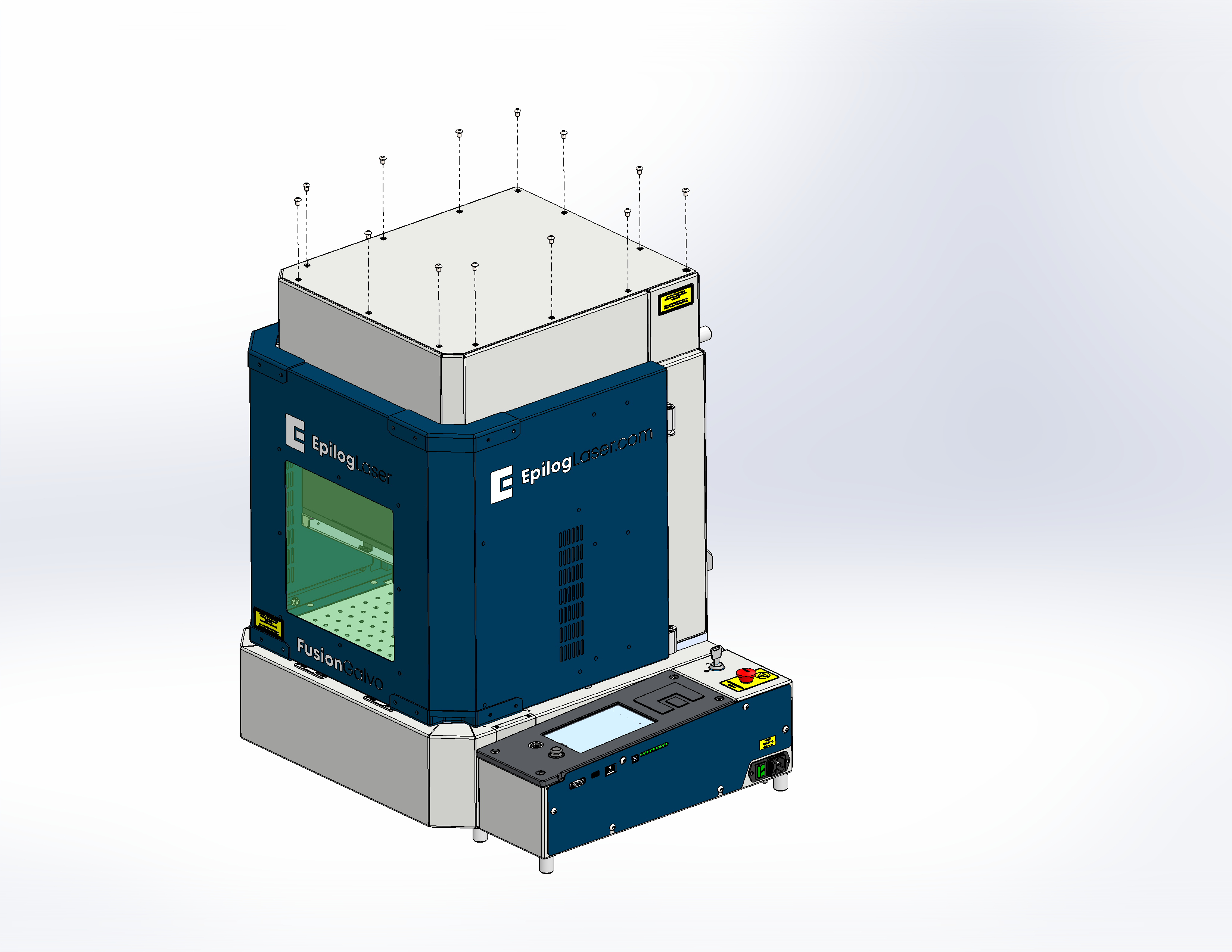
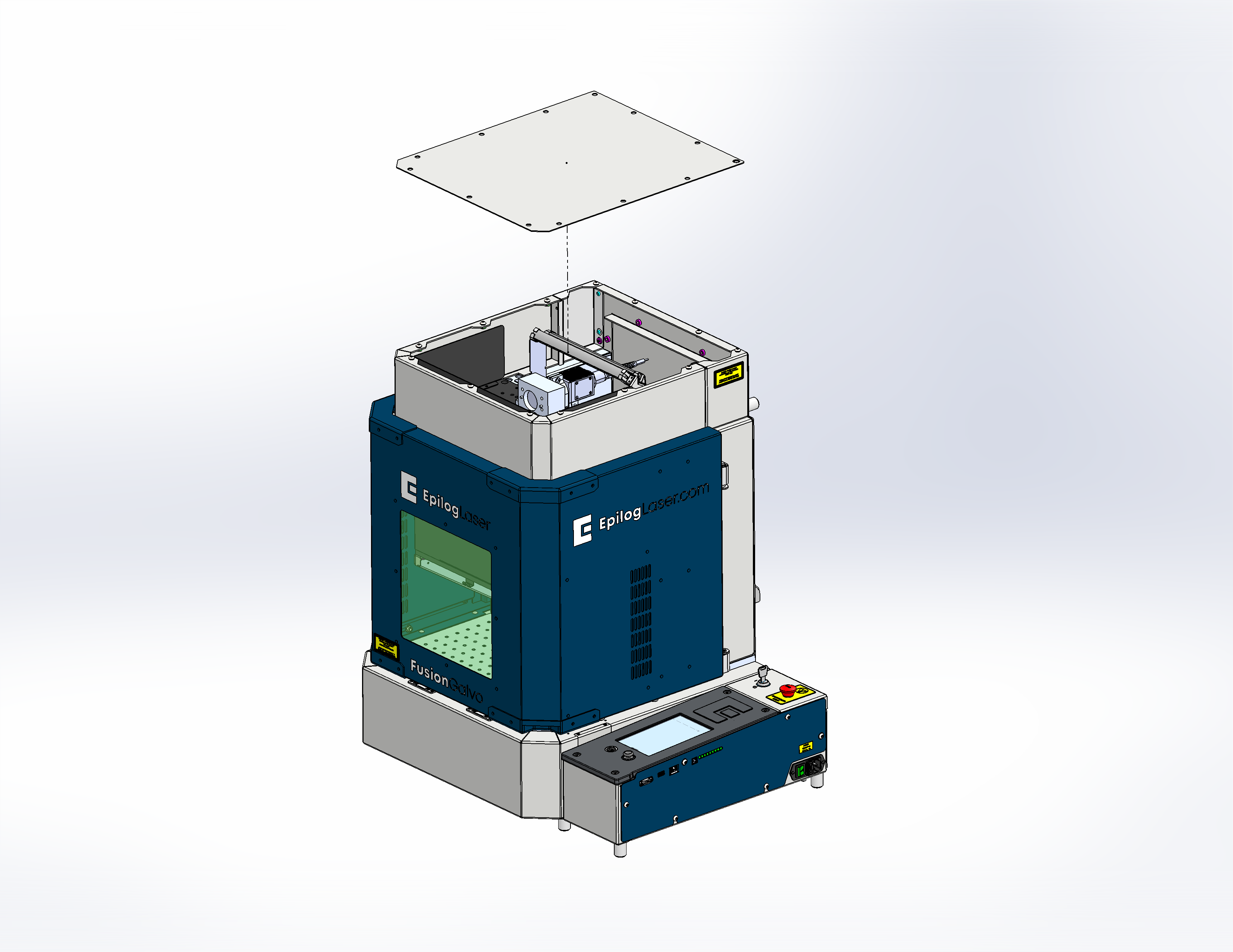
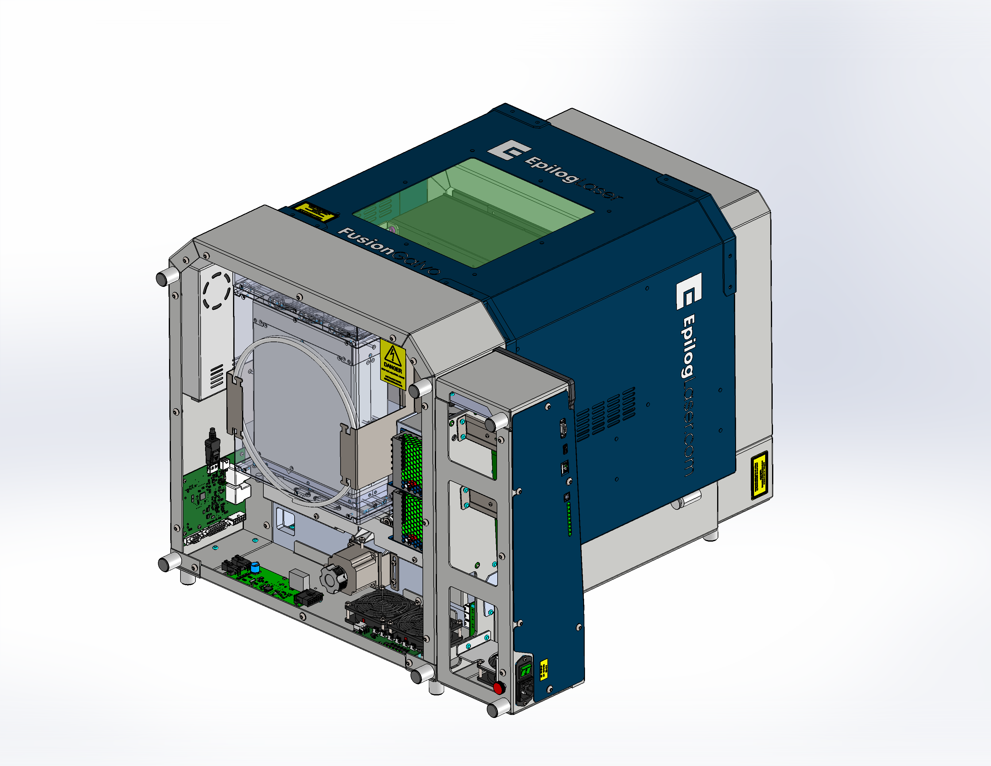
Remove the top panel.
![]()
Figure 6a. Top panel screws removed. ![]()
Figure 6b. Top panel removed. -
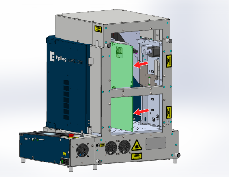
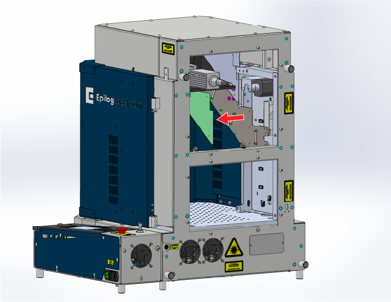
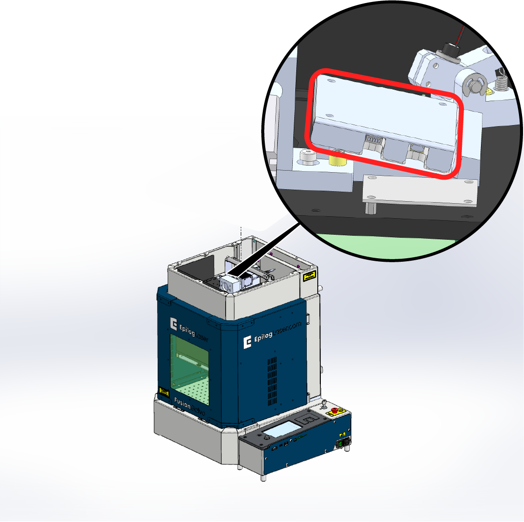
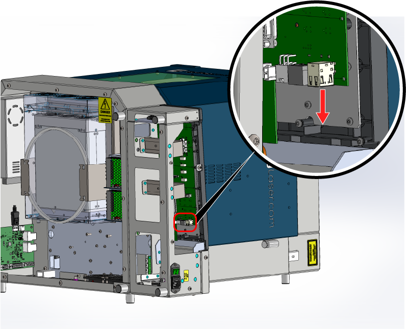
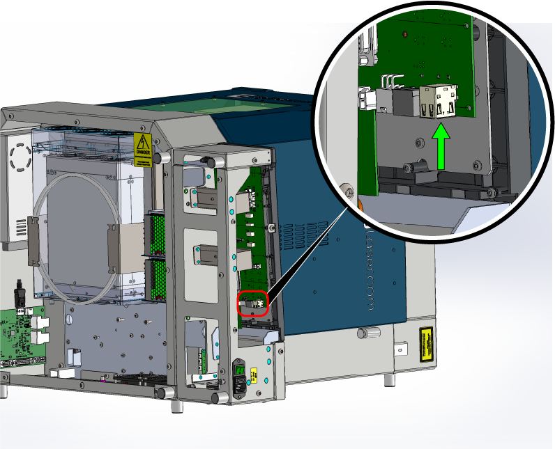
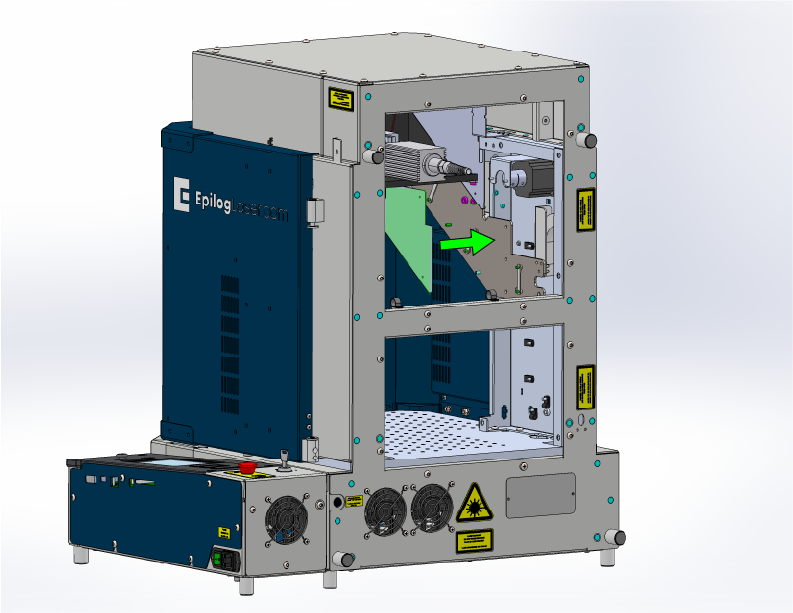
Remove the camera cover and disconnect the camera cable.
![]()
Figure 7. Camera cover removed and cable disconnected. -
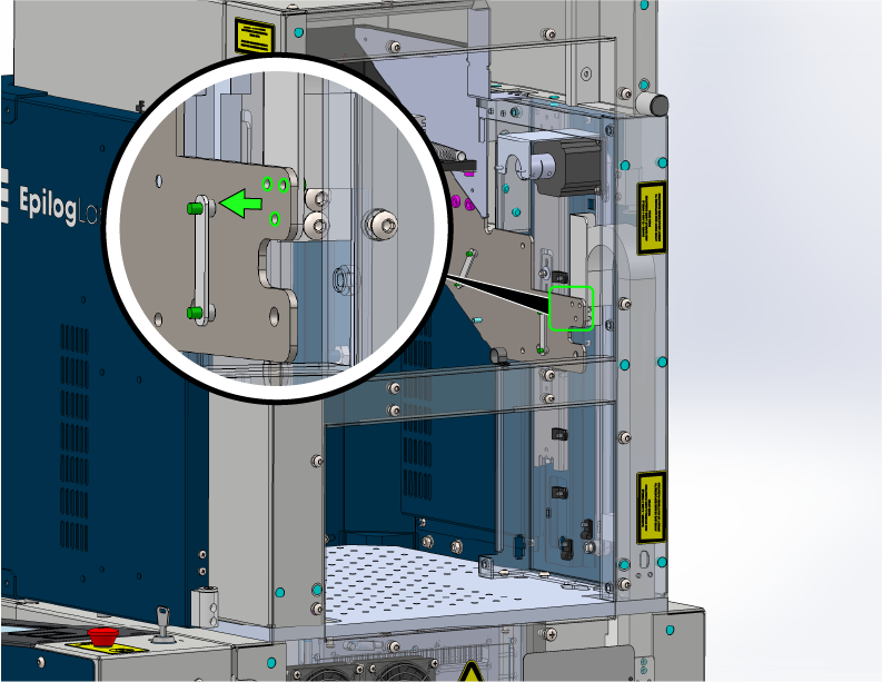
Remove the cable hold-downs.
![]()
Figure 8. Cable hold-downs removed. -
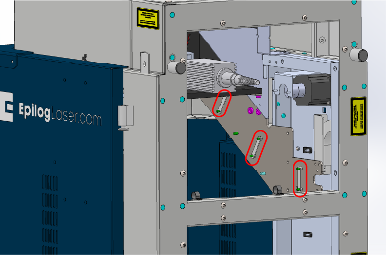
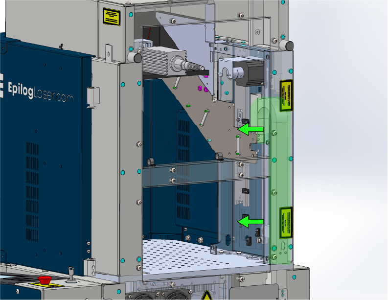
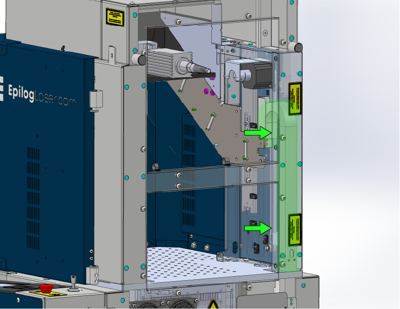
Remove the screws securing the cable track.
![]()
Figure 9a. Cable track top screws highlighted. ![]()
Figure 9b. Cable track bottom screws highlighted. -
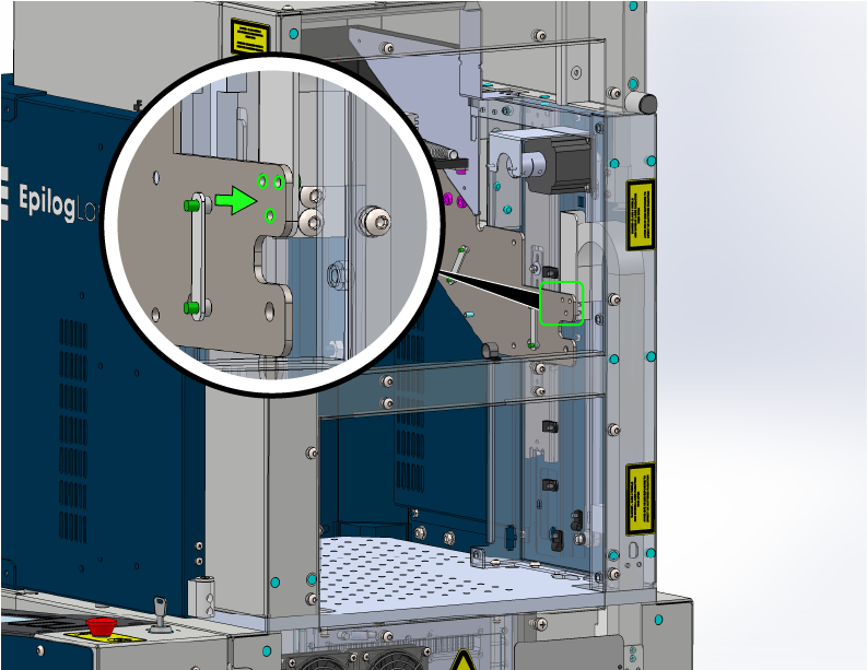
Carefully remove the cable track.
Straightening the track will help when pulling the cable out through the bottom.
![]()
Figure 10. Cable track removed. -
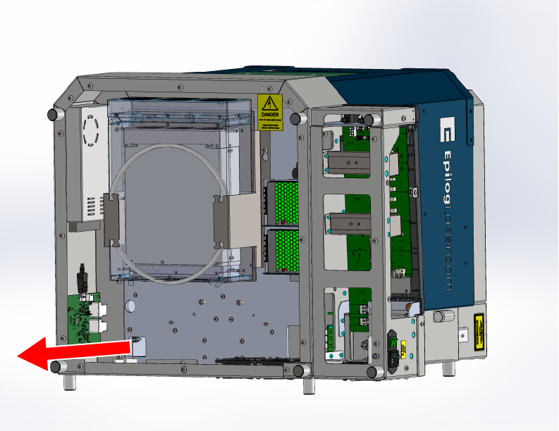
Tilt the machine onto its back and remove the side cover.
Use two people to avoid injury and protect the machine.
![]()
Figure 11. Side cover removed. -
Remove the bottom panel.
![]()
Figure 12a. Bottom panel screws removed. ![]()
Figure 12b. Bottom panel removed. -
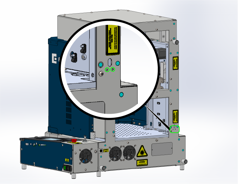
Disconnect the cable from the control board.
![]()
Figure 13. Control board end of cable disconnected. -
Verify the cable is free, then feed it out the bottom of the machine.
Cut any remaining zip ties holding the cable and pull it completely free.
![]()
Figure 14. Cable fully removed from the machine.
Installation
-
Feed the new cable up through the bottom of the machine.
Route the cable through the opening and up into the interior, matching the original path.
![]()
Figure 15. Routing the new cable upward through the machine. -
Reconnect the cable to the control board.
Ensure the connector seats fully and securely.
![]()
Figure 16. New cable attached to the control board. -
Reinstall the side cover.
![]()
Figure 17. Side cover reinstalled. -
Reinstall the bottom panel and return the machine upgright.
Use two people to lift safely.
![]()
Figure 18. Bottom panel reinstalled. -
Reinstall the cable track.
Ensure the cable sits naturally in the channel.
![]()
Figure 19. Cable track reinstalled. -
Reinstall the cable track screws.
Tighten evenly to prevent binding.
![]()
Figure 20a. Cable track top screws reinstalled. ![]()
Figure 20b. Cable track bottom screws reinstalled. -
Reinstall the cable hold-downs.
Verify routing follows original path.
![]()
Figure 21. Cable hold-downs reinstalled. -
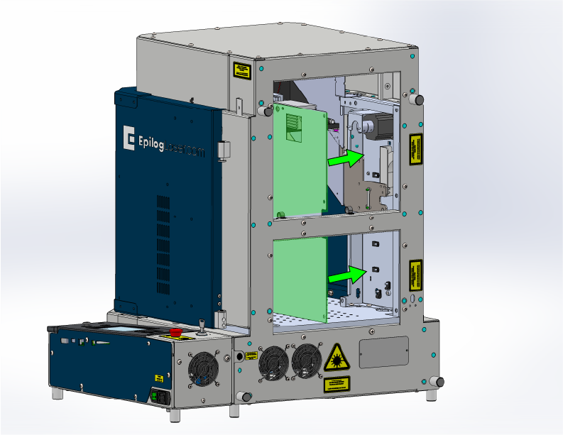
Reconnect the camera cable and reinstall the camera cover.
![]()
Figure 22. Camera cable and cover installed. -
Reinstall the top panel.
![]()
Figure 23a. Top panel screws reinstalled. ![]()
Figure 23b. Top panel installed. -
Reinstall the inner side panels.
![]()
Figure 24a. First inner side panel installed. ![]()
Figure 24b. Second inner side panel installed. -
Reinstall the rear panels.
![]()
Figure 25a. Rear panel screws installed. ![]()
Figure 25b. Rear panels installed. -
Reconnect and power on the machine.
Open the software to verify camera function. Run a job to confirm alignment.
![]()
Figure 26. Camera test and verification.
Note: If the camera does not appear, verify cable seating at both ends, check for pinched cable sections, and run the camera update.