To ensure your CO2 laser engraver delivers optimal performance and consistent cutting quality, proper beam alignment is essential. Over time, vibration, wear, or component replacement can cause the laser beam to deviate from its intended path. This can result in reduced cutting power, inconsistent engraving, or premature wear of optics.
This procedure outlines how to realign the laser beam by systematically checking and adjusting the position of the red dot pointer and the system mirrors. By following these steps, you will restore a clean, coaxial path for the laser beam, from the tube to the lens, ensuring the engraver operates efficiently and safely.
When to Align the Laser
If you have replaced any of these parts:
- Laser Tube
- Mirror 1, 2, or 3
- X-Axis Assembly
- Red Dot Pointer
If you experience any of these symptoms:
- Laser power appears weak in certain areas of the table.
- The engraver is unable to effectively cut through materials with known settings.
- Optics in the lens assembly fail prematurely.
- If the engraver has been moved to a new location.
Table of Contents
- Pre-Alignment (red dot alignment)
- Laser Alignment
- Perpendicular Alignment
Safety Statement: It is strongly advised not to activate the laser with the panels removed. Always wear appropriate eye protection, such as Lexan or polycarbonate safety glasses, when operating the laser with the panels off.
Pre-Alignment (red dot alignment)
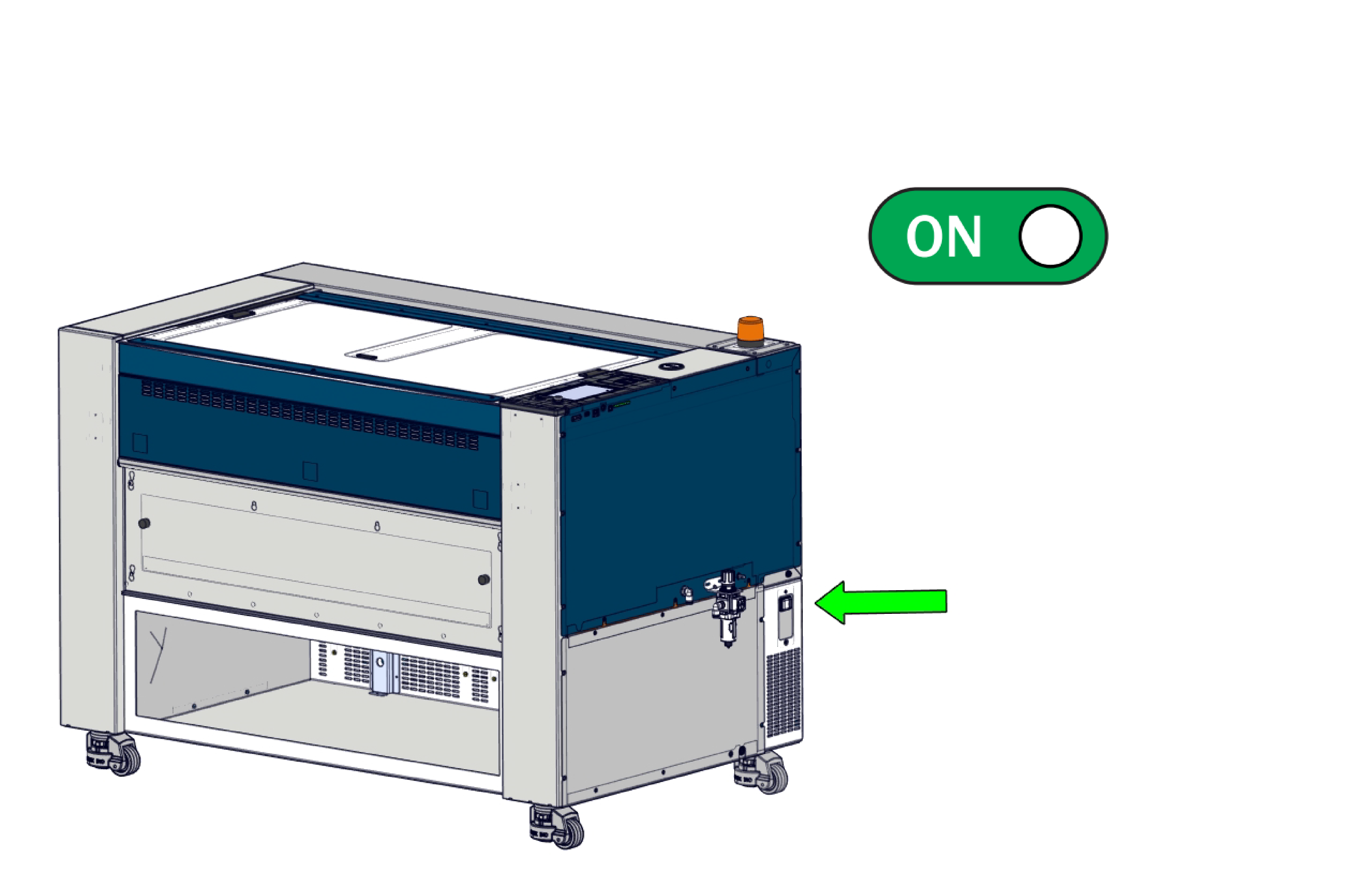
1. Power ON the machine
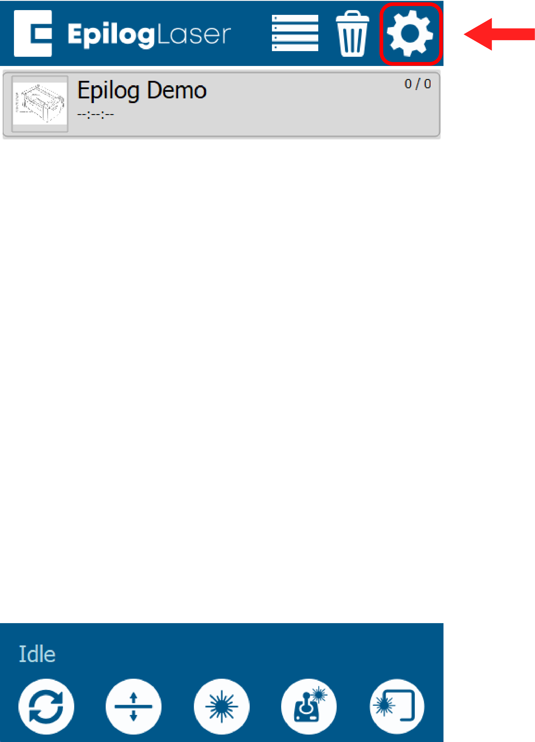
2. Press the Gear icon
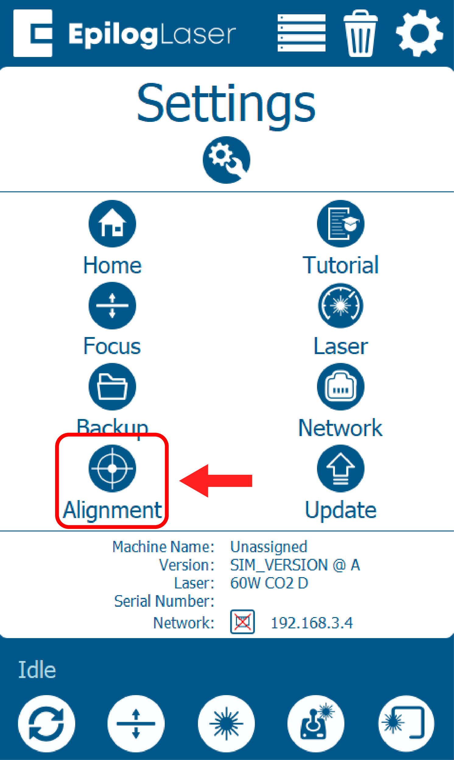
3. Select Alignment
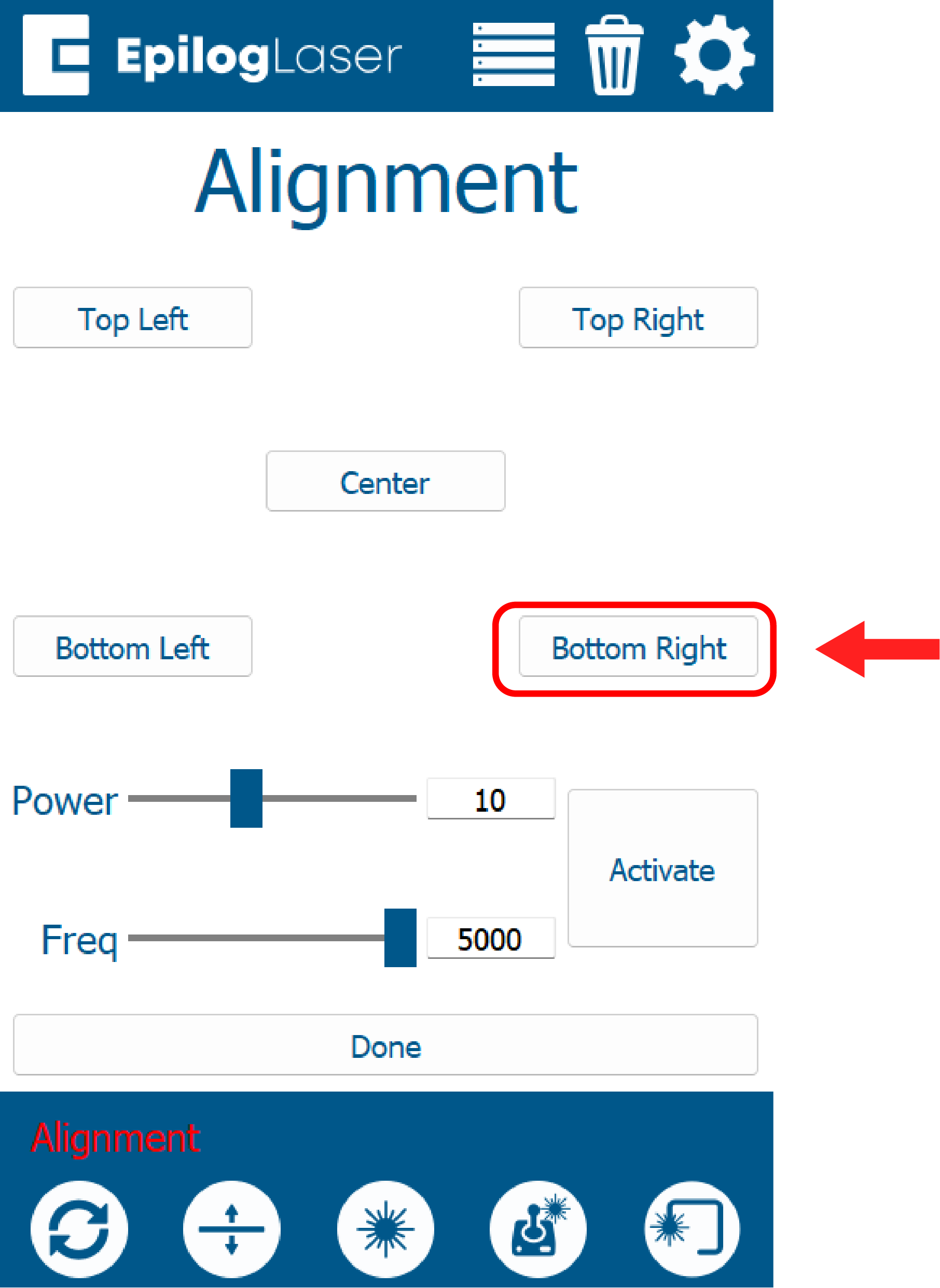
4. Clear the bed of any material, and select Bottom Right.
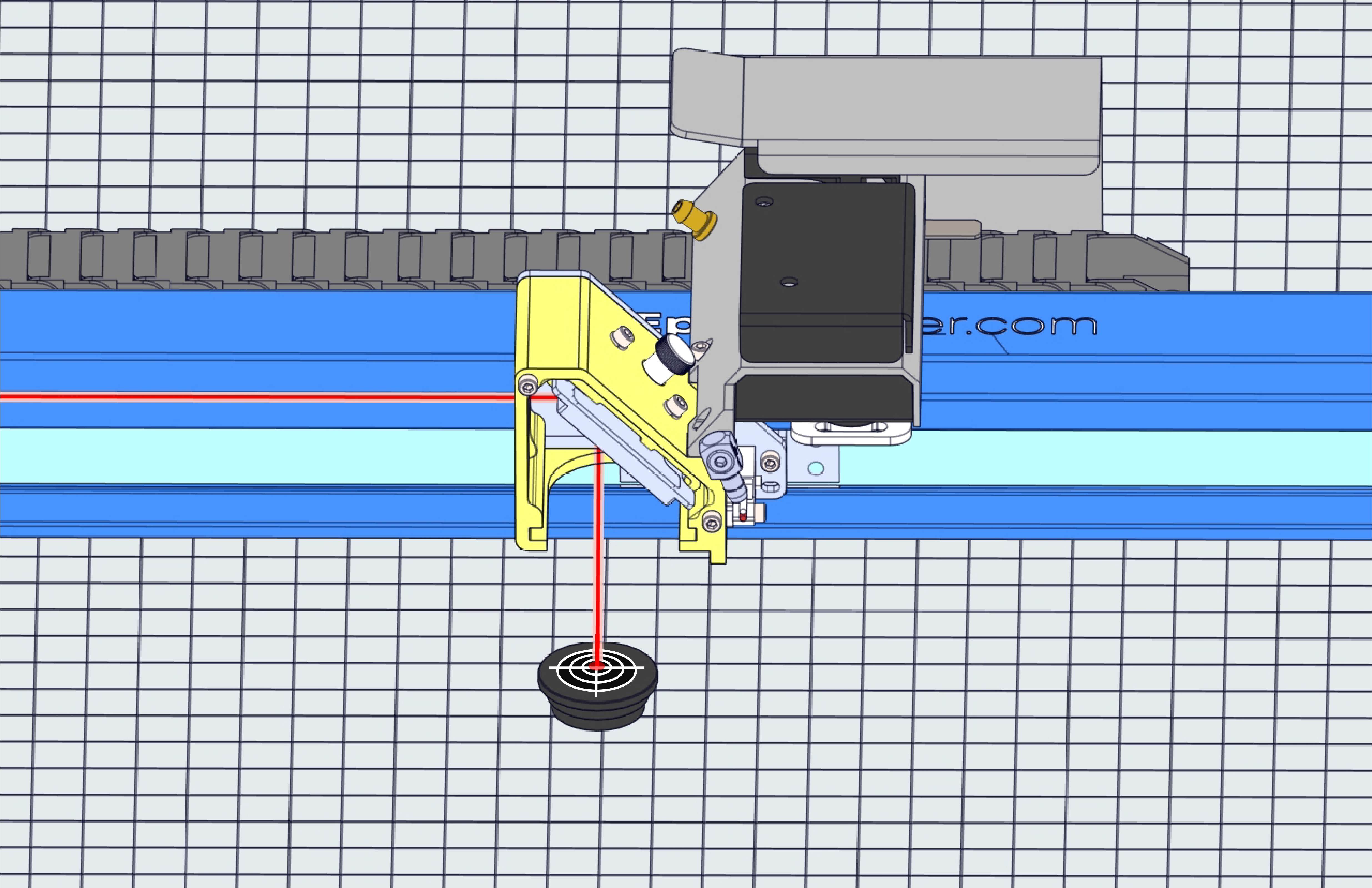
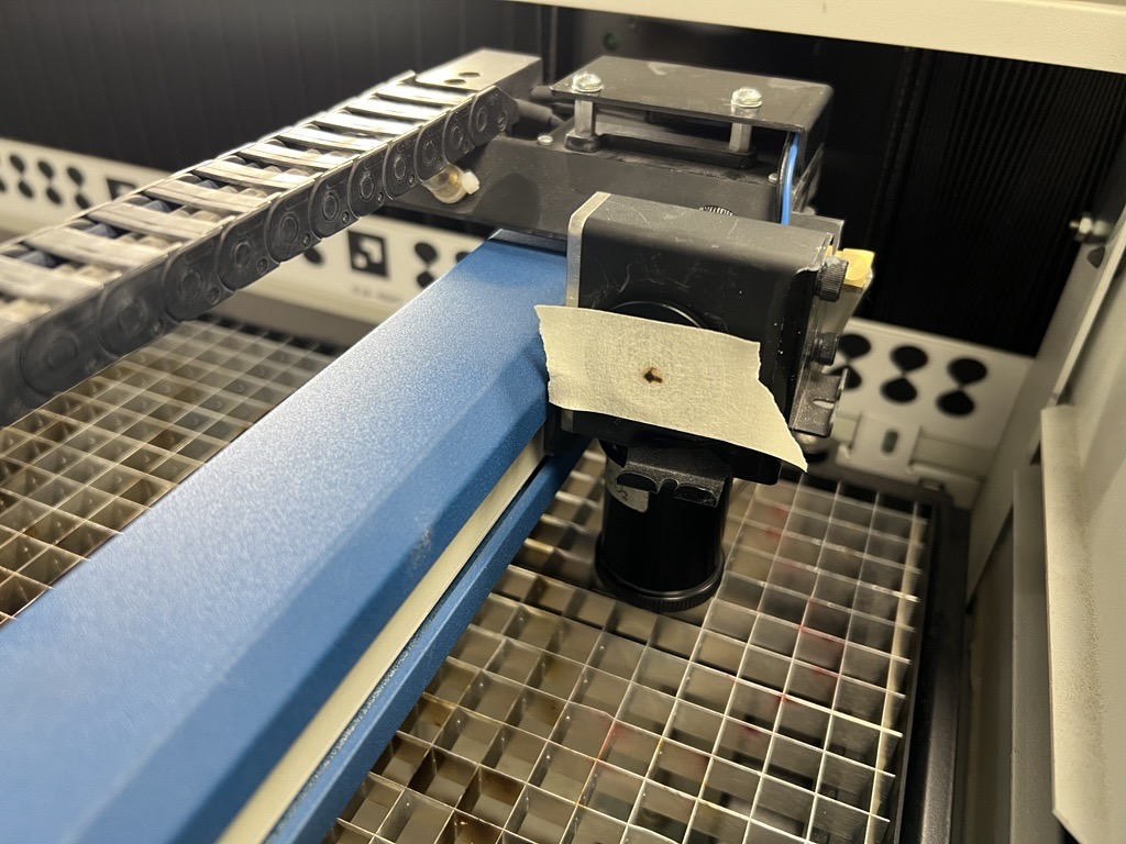
5.Apply masking tape to the alignment target, and insert target into carriage.
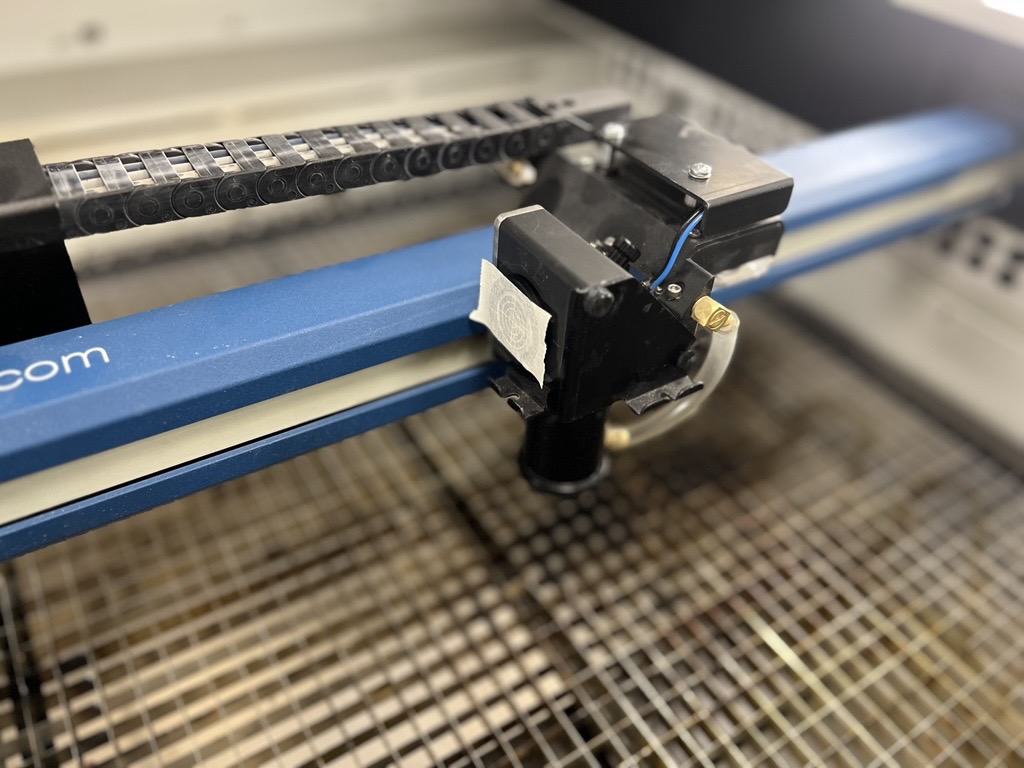
7. Tap the activate button 2-3 times and watch for a burn mark on the tape.
Note: If you are unable to make a burn mark in position 4 (bottom right), the laser may be significantly misaligned. Use a larger piece of masking tape to increase the target area. If a burn mark still does not appear, move the carriage to the top left (home position) and tap activate. Align the red dot to the burn mark, complete the alignment steps, then return to the bottom right and repeat the pre-alignment and alignment procedures.
8. Turn on the red dot pointer, verify the red dot and burn mark are in same position.
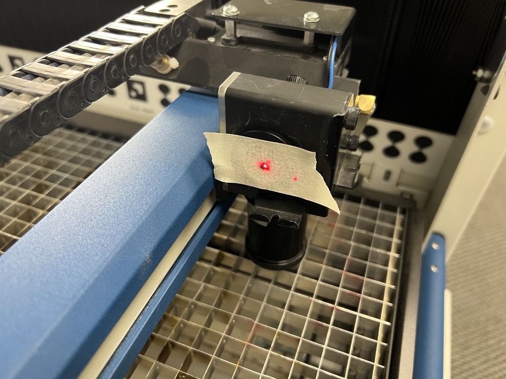
9. If the red dot is not aligned with the burn mark, adjust the red dot pointer.
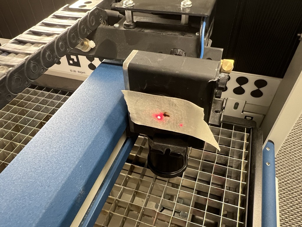
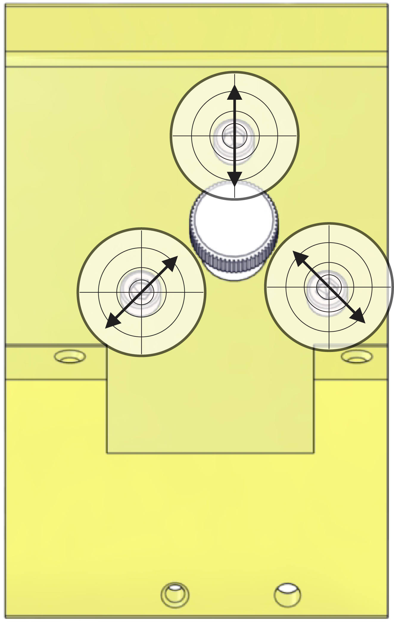
11. Using the two 3/32″ adjustment screws on the red dot, move the red dot to the position of the burn mark.
Note: Keep the carriage in the same position where the burn mark was made. The key to this step is getting the red dot and burn mark in the same position, not their overall location within the alignment target.
12. When the position of the red dot matches the burn mark, remove the masking tape and continue with the laser alignment.
Laser Alignment
It is essential that the cutting laser and the red dot pointer are perfectly aligned (coaxial) before beginning this process. If the red dot pointer and cutting laser are not in the same position, you will be unable to properly align the laser.
For alignment purposes, the table of the engraver is separated into four (4) quadrants or table positions. The location of each quadrant is determined by its relative distance from the laser.
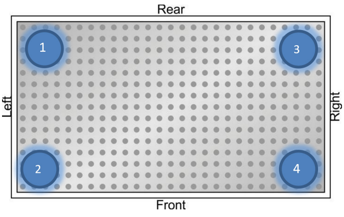
Mirror Locations
There are four (4) mirrors that may need to be adjusted in order to align the CO2 laser. Each mirror is referenced by a number and corresponds to a specific table position. Only adjust the mirror that controls it’s corresponding position.
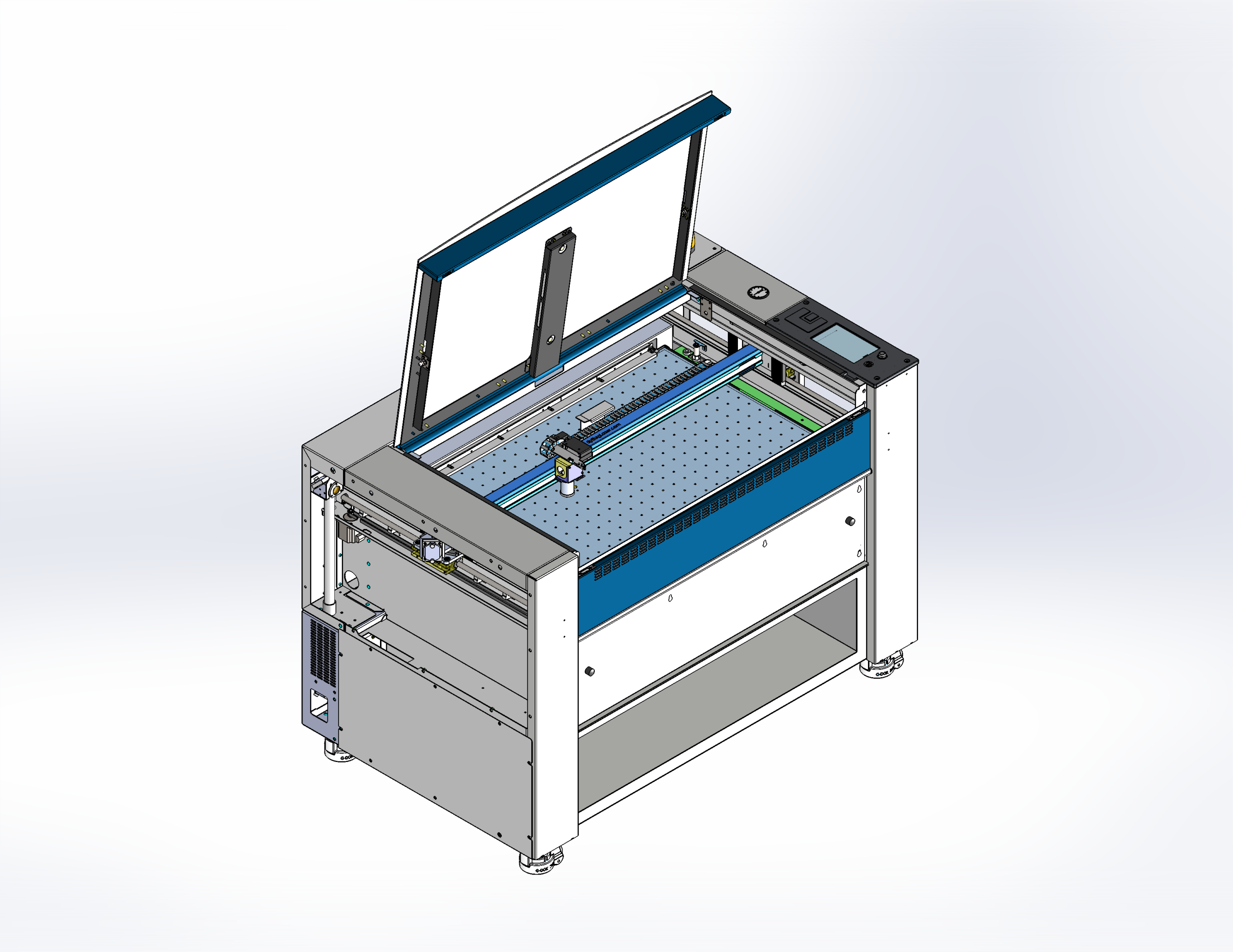
3. Press the Top Left button on the display panel.
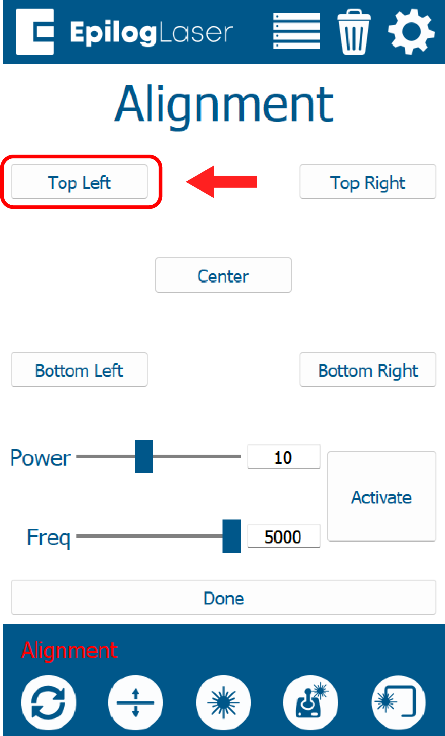
5. Press the Top Right button on the display panel.
7. Press the Bottom Right button on the display panel.
9. Press the Bottom Right button on the display panel.
Perpendicular Alignment
The objective of perpendicular alignment is to align the laser through the lens tube. The path must be perpendicular to the table and centered through the lens tube. This is acomplished by carefully adjusting mirror four (4).
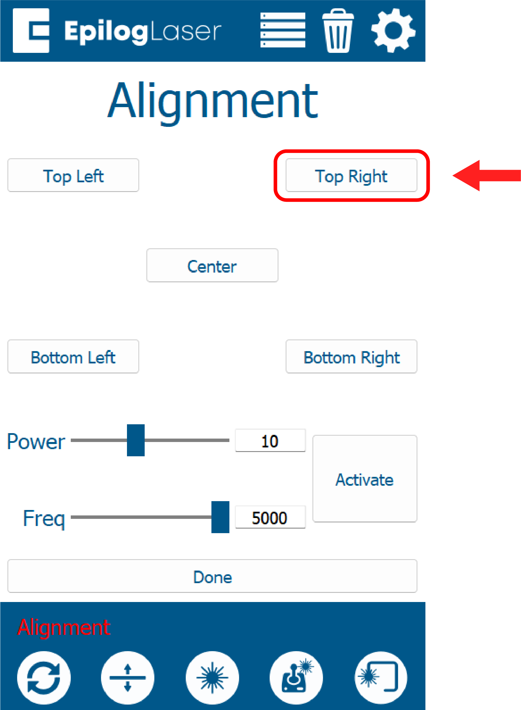
1. Press the Center button on the display panel.
8. Place the target on the table centered under the red dot.