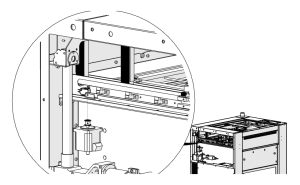
This guide covers replacing a y-axis actuator on the Fusion Pro 32 and 48. The drawings show the left actuator on a Fusion Pro 48 (CS0520), but the process is similar for every y-axis actuator on these machines. The x-axis assembly is lifted off the bearing blocks to remove the actuator, and the new actuator is squared to the x-axis before its screws are tightened.
Parts Required
- CS1130 – Assy, Actuator, Y-Axis, Right, 32×20
- CS1140 – Assy, Actuator, Y-Axis, Left, 32×20
- CS0500 – Assy, Actuator, Y-Axis, Right, 48×36
- CS0520 – Assy, Actuator, Y-Axis, Left, 48×36
Tools / Materials Required
- 5/32" and 7/64" Allen Wrenches
- Phillips Screwdriver
- Anti-Static Strap
Safety First: Ensure the engraver is completely powered off and the power cord is disconnected before removing any panels or touching internal components.
Y-Axis Actuator Removal
Turn Off Engraver
Turn off the engraver.
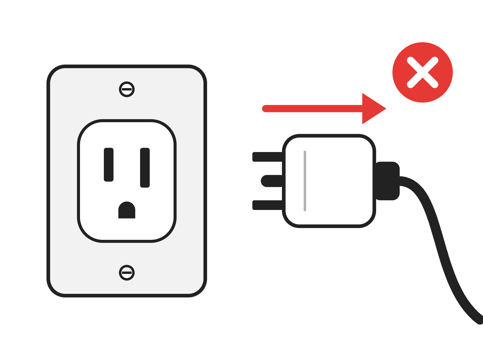
Disconnect from Power
Unplug the engraver from its power source.
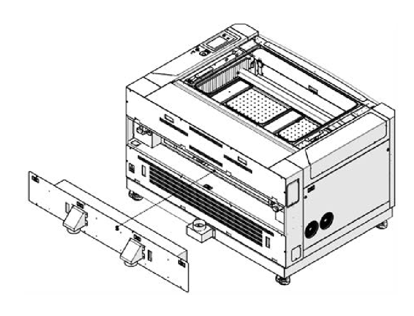
Remove Exhaust Plenum
Remove the exhaust plenum from the rear of the engraver.
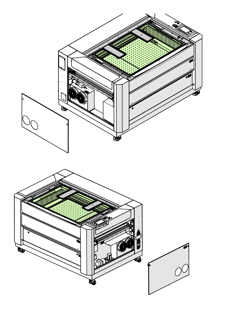
Remove Side Panels
Remove the left and right panels of the engraver.
Loosen Drive Board Cover Screws
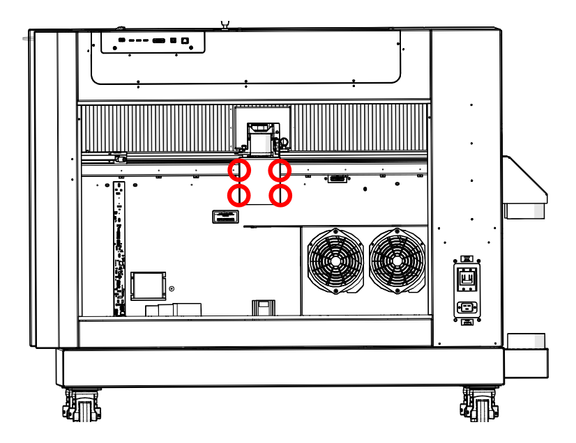
Loosen, but do not remove, the four Phillips screws on the x-axis drive board cover (circled in red).
Remove Drive Board Cover
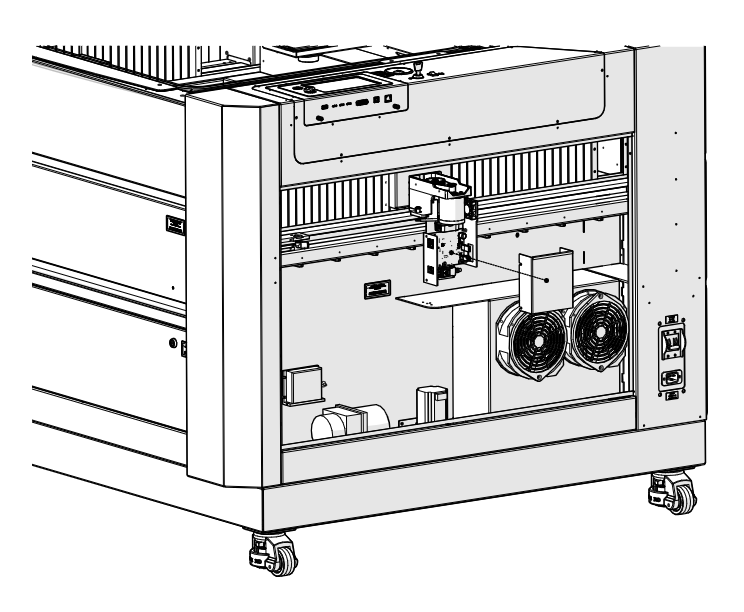
Remove the x-axis drive board cover.
Put On Anti-Static Strap
Place the anti-static strap around your wrist and attach the clamp to a bare metal surface in the engraver. Keep it on while you handle the drive boards.
Disconnect X-Axis Drive Board
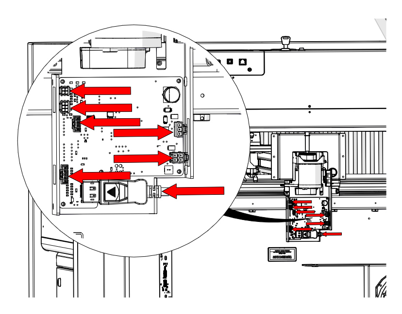
Disconnect the seven electrical connectors from the x-axis drive board (red arrows).
Remove X-Axis Drive Board Screws
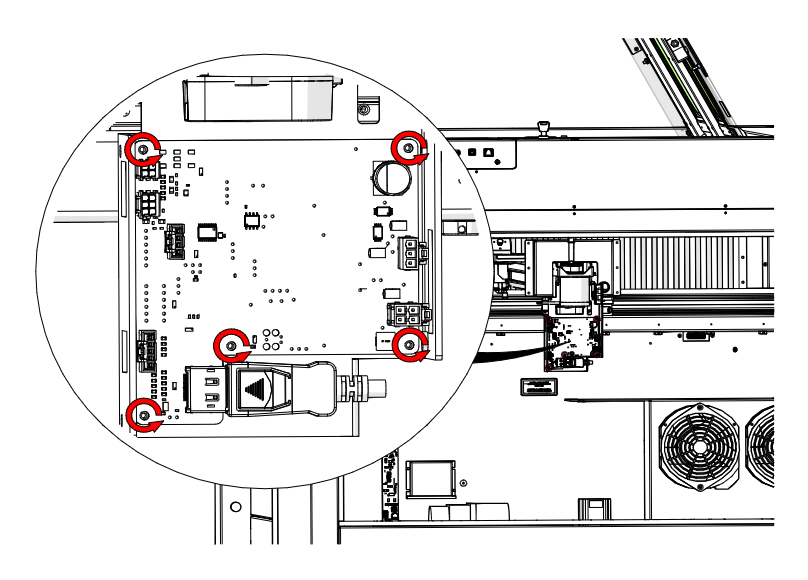
Loosen and remove the five Phillips screws that secure the x-axis drive board to its housing (circled in red).
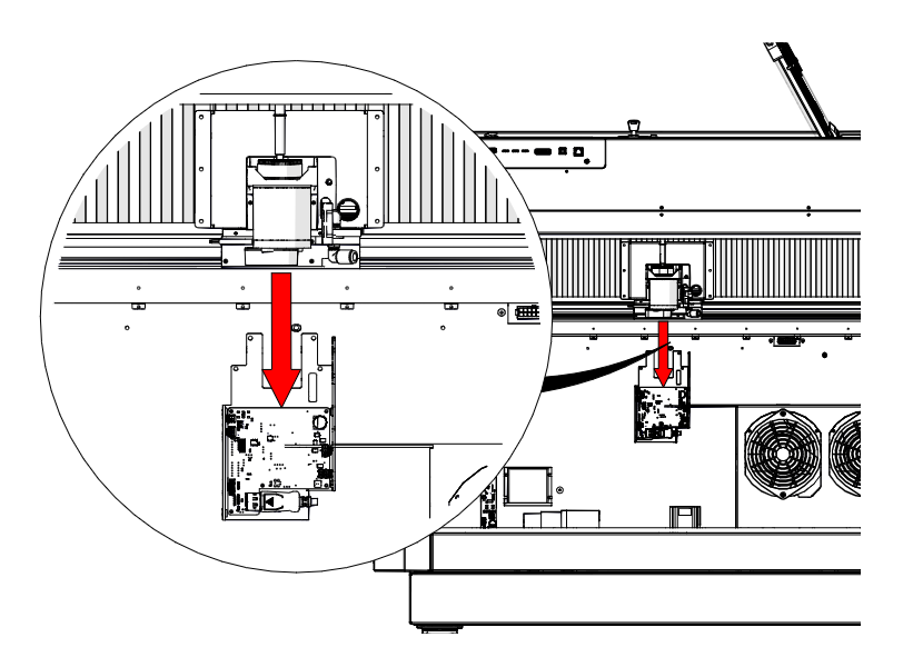
Remove Drive Board Housing
Remove the x-axis drive board housing.
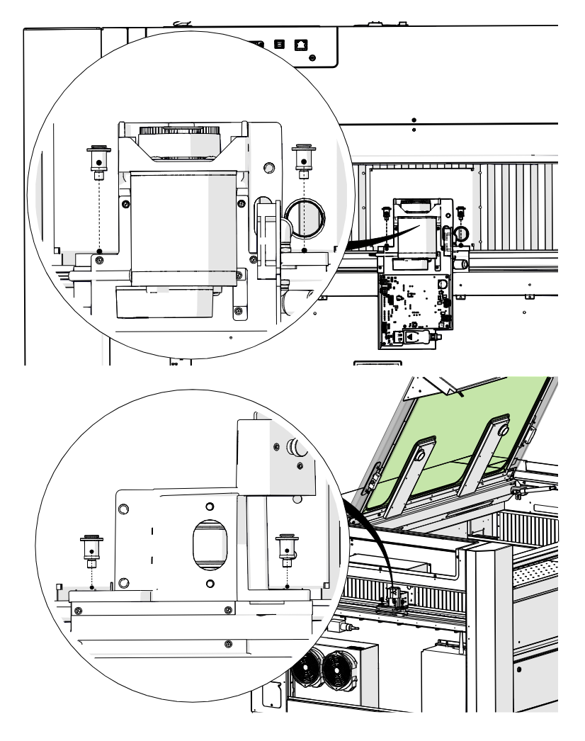
Remove X-Axis Fasteners
Remove or loosen the four 5/32" fasteners that secure the x-axis assembly to the y-axis bearings: two on the right side (top) and two on the left side (bottom).
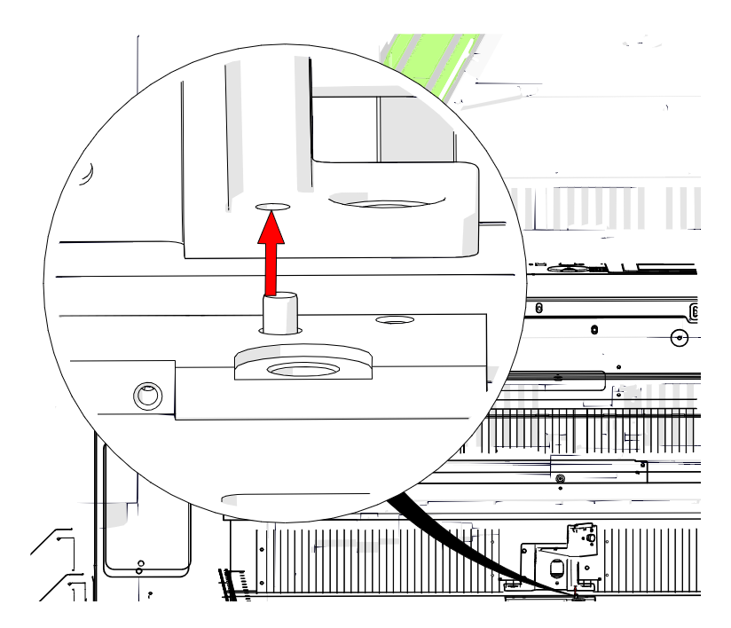
Lift the X-Axis Assembly
Lift the x-axis assembly up to clear the locator pins on the left and right y-axis bearing blocks.
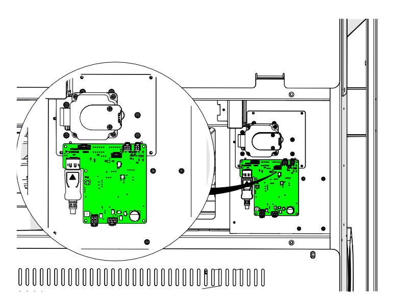
Disconnect Y-Axis Drive Board
Disconnect the seven electrical connectors from the drive board at the rear of the actuator you are replacing.
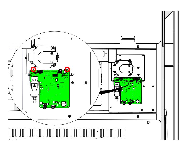
Remove Y-Axis Drive Board
Loosen and remove the two Phillips screws that secure the drive board assembly to the y-axis actuator (circled in red), then set the drive board assembly aside.
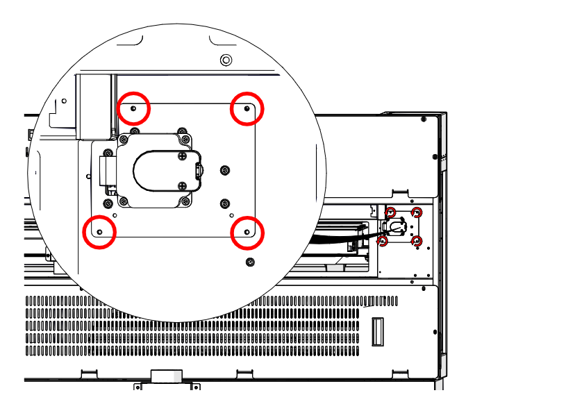
Remove Rear Actuator Screws
Loosen and remove the four 7/64" Allen screws that secure the y-axis actuator to the rear of the engraver chassis (circled in red).
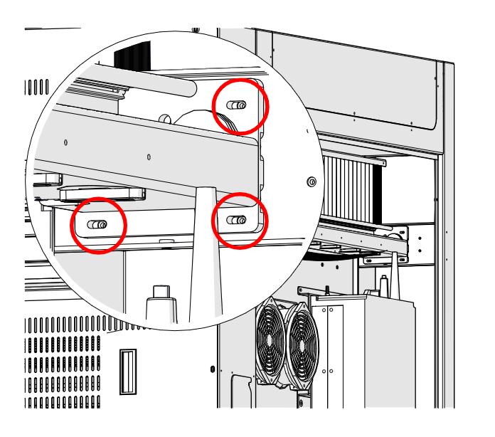
Remove Front Actuator Screws
Loosen and remove the three 7/64" Allen screws that secure the y-axis actuator to the front of the engraver chassis (circled in red).
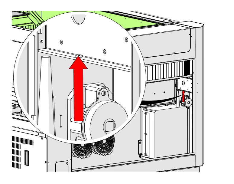
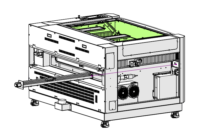
Leave the Height Screw Alone
Do not adjust the screw shown here (red arrow).
Important: This screw sets the height of the y-axis actuator at the front of the engraver and should not be adjusted.
Remove the Y-Axis Actuator
Slide the y-axis actuator out through the rear of the engraver.
Y-Axis Actuator Installation
Install the New Actuator
Slide the new y-axis actuator in through the rear of the engraver.
Install Front Actuator Screws
Install, but do not fully tighten, the three 7/64" Allen screws that secure the y-axis actuator to the front of the engraver chassis.
Install Rear Actuator Screws
Install, but do not fully tighten, the four 7/64" Allen screws that secure the y-axis actuator to the rear of the engraver chassis.
Check the Anti-Static Strap
Make sure the anti-static strap is still around your wrist and clamped to bare metal on the engraver.
Install Y-Axis Drive Board
Place the drive board assembly in the engraver. Install and tighten the two Phillips screws that secure it to the y-axis actuator.
Connect Y-Axis Drive Board
Connect the seven electrical connectors to the drive board at the rear of the actuator.
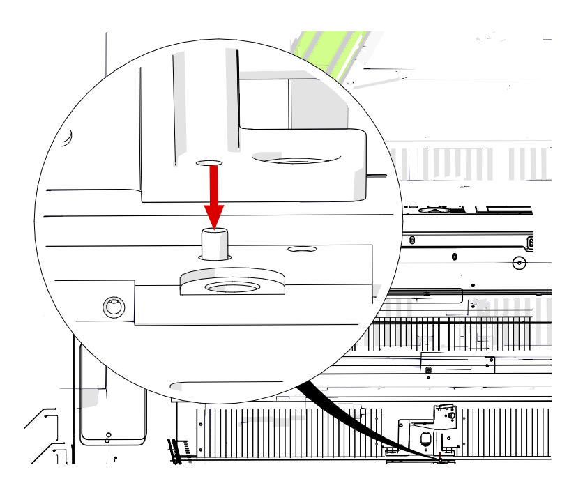
Seat the X-Axis Assembly
Place the x-axis assembly on the y-axis bearing blocks, making sure the locator pins go into the upper bearing block assembly.
Install X-Axis Fasteners
Install and tighten the four 5/32" fasteners that secure the x-axis assembly to the y-axis bearings: two on the right side and two on the left side.
Reinstall X-Axis Drive Board
Install the x-axis drive board in its housing with the five Phillips screws.
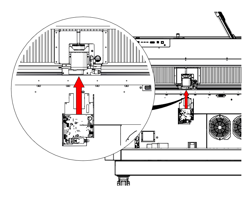
Position Drive Board Housing
Position the x-axis drive board housing over its mounting holes.
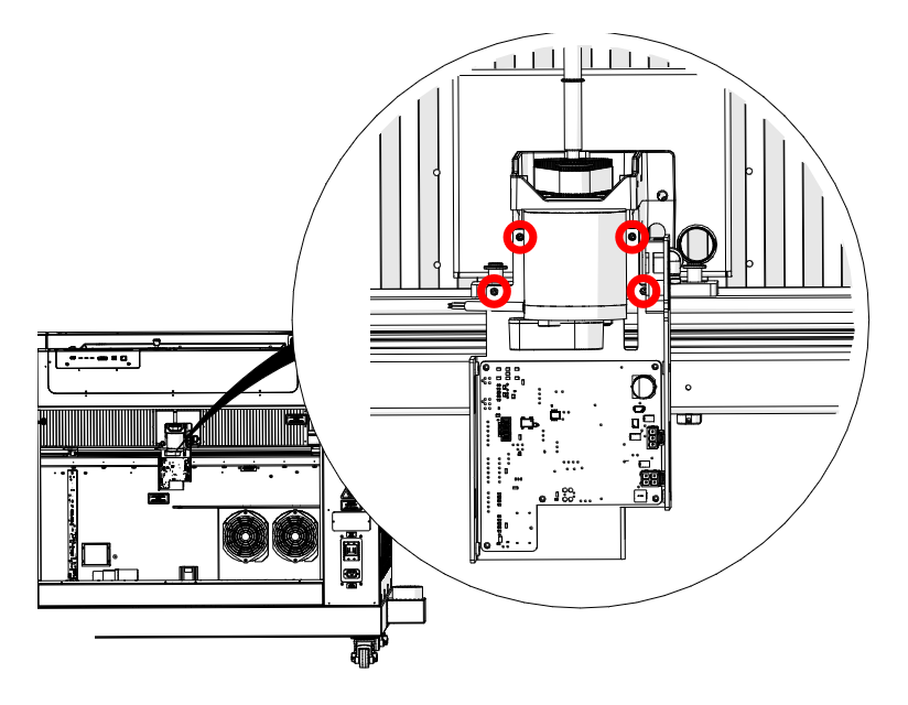
Install Drive Board Housing Screws
Install and tighten the four 7/64" hex screws that hold the x-axis drive board housing.
Connect X-Axis Drive Board
Connect the seven electrical connectors to the x-axis drive board.
Note: Each connector on the drive board is unique and only fits one receptacle.
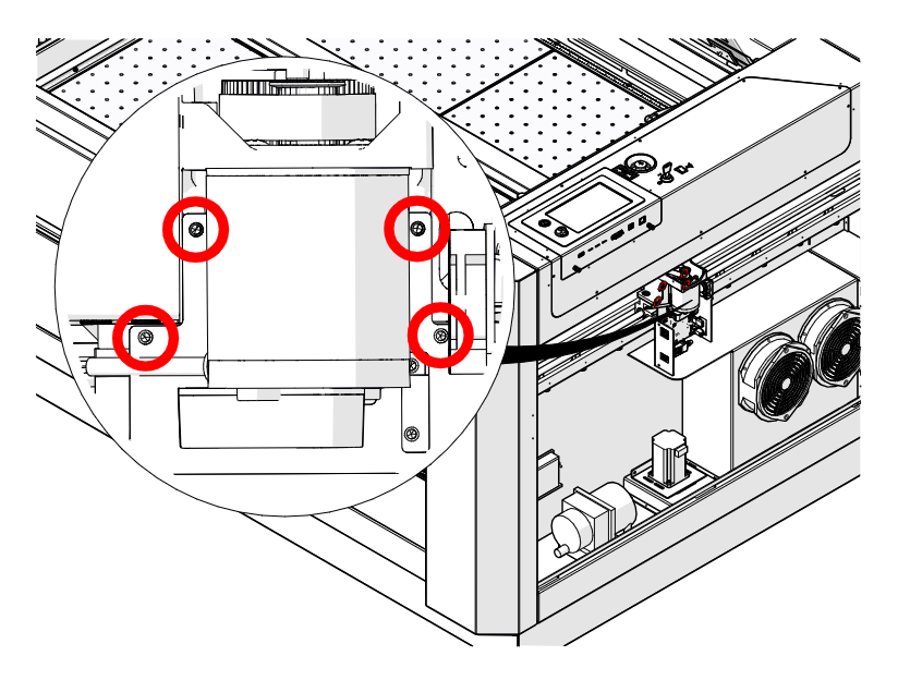
Install Drive Board Cover
Install the x-axis drive board cover and tighten the four Phillips screws.
Squaring the Y-Axis Actuators
Check the Actuator Screws
Make sure the mounting screws on the new y-axis actuator are not fully tightened yet.
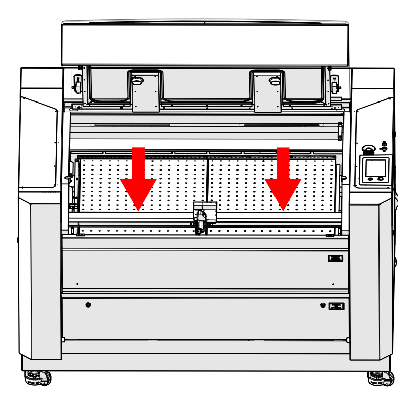
Square at the Front
Manually move the x-axis assembly to the front of the engraver, making sure it is square to the front of the machine.
Tighten Front Actuator Screws
Tighten the three 7/64" screws that secure the y-axis actuator to the chassis at the front of the engraver.
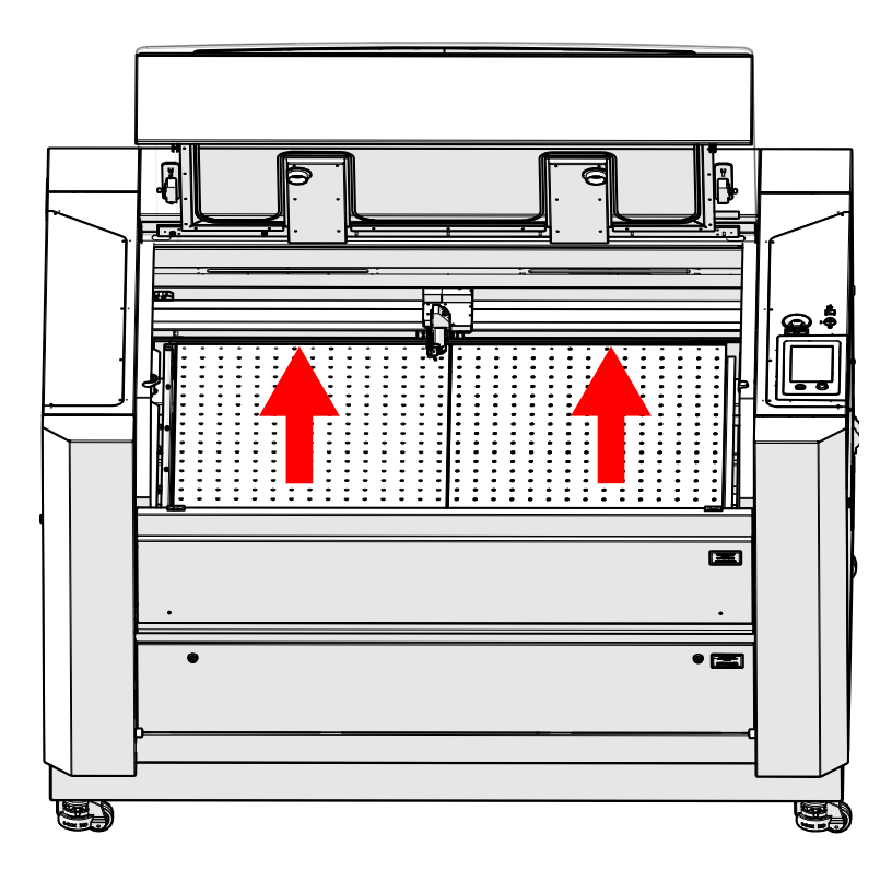
Square at the Rear
Manually move the x-axis assembly to the rear of the engraver, making sure it is square to the rear of the machine.
Tighten Rear Actuator Screws
Tighten the four 7/64" screws that secure the y-axis actuator to the chassis at the rear of the engraver.
Install Panels and Plenum
Install the left and right panels and the exhaust plenum.
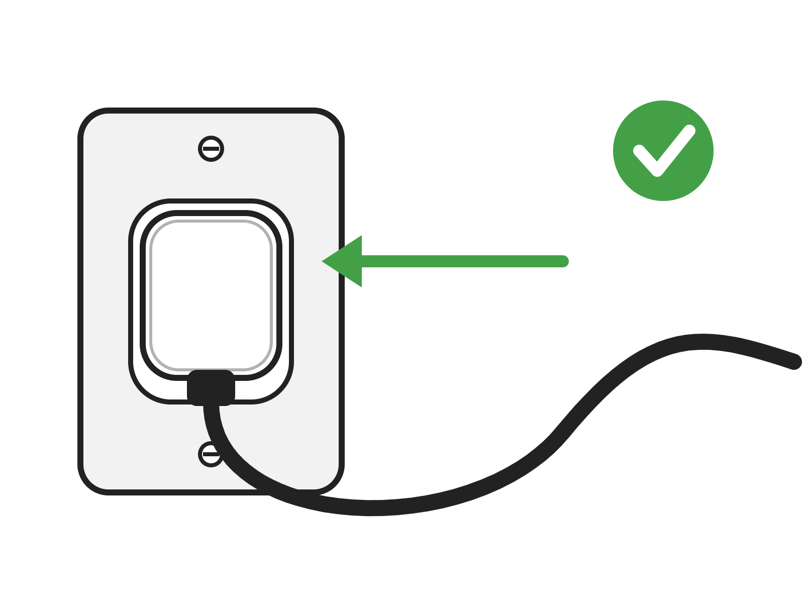
Power On
Reconnect the engraver to power and turn it on.