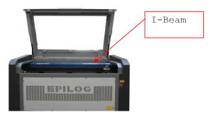
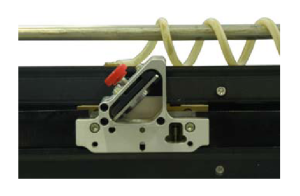
This guide covers removing and reinstalling the X-axis assembly (I-beam) on the Legend 36EXT. Careful handling and placement of the I-beam keeps the engraver’s motion accurate.
Parts Required
- X-Axis Assembly (I-Beam)
Tools Required
- Phillips Screwdriver
Safety First: Ensure the engraver is completely powered off and the power cord is disconnected before removing any panels or touching internal components.
I-Beam Removal
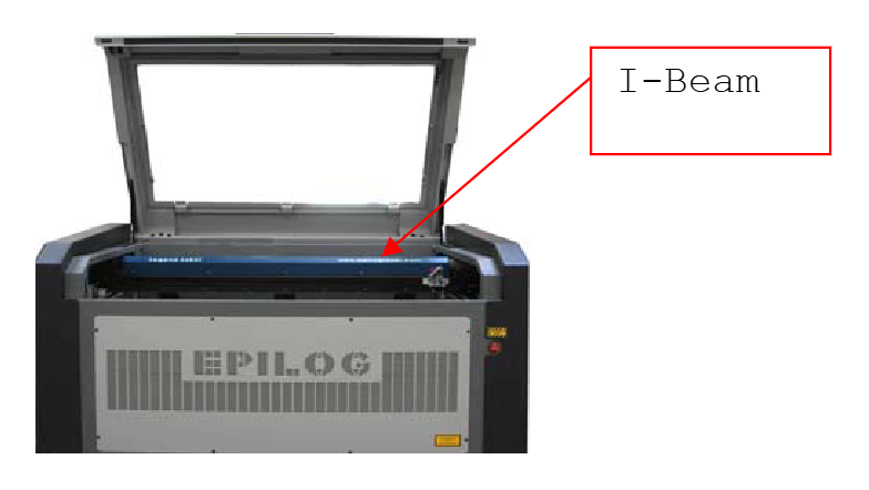
Center the I-Beam
Move the I-beam to the center of the engraver.
Power Off Engraver
Turn off the engraver.
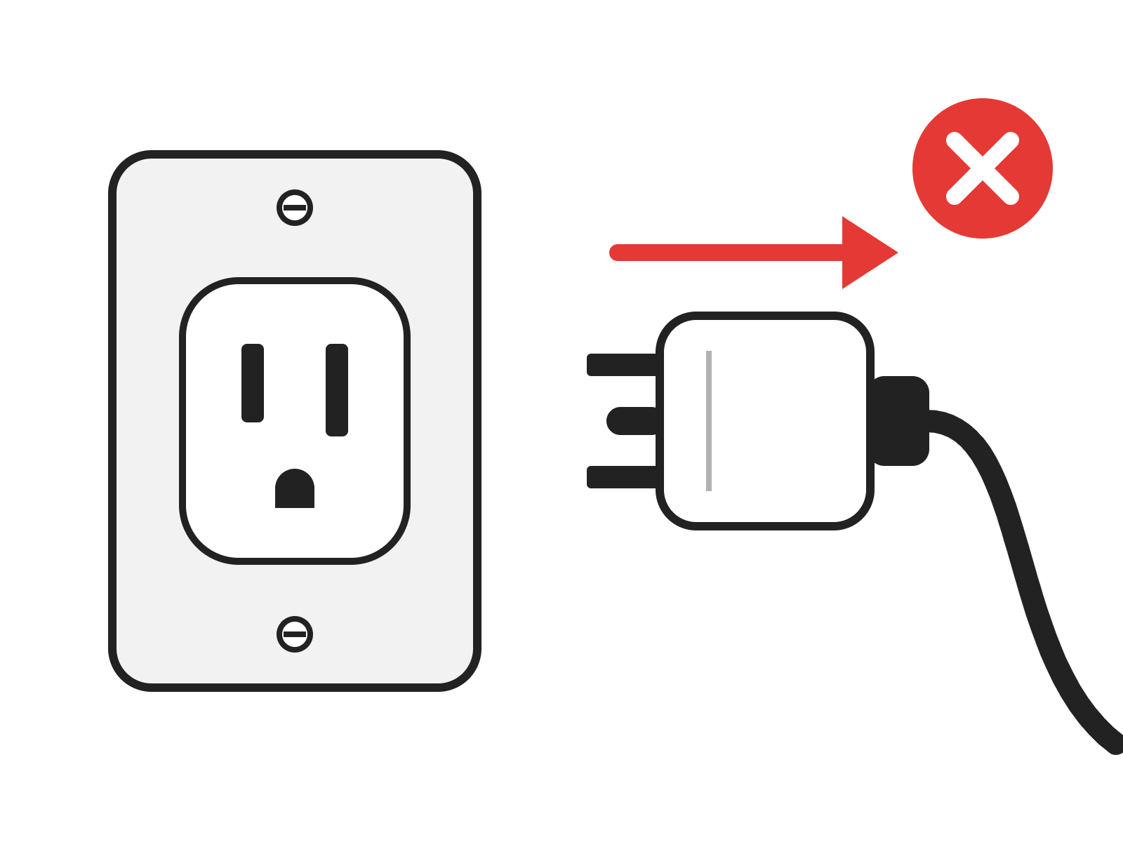
Disconnect From Power
Unplug the power cord from the engraver.
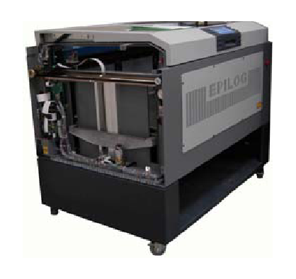
Remove the Left Side Panel
Remove the left side panel.
Note: Three screws also hold this panel to the back of the engraver.
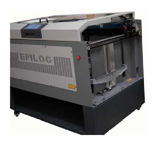
Remove the Right Side Panel
Remove the right side panel.
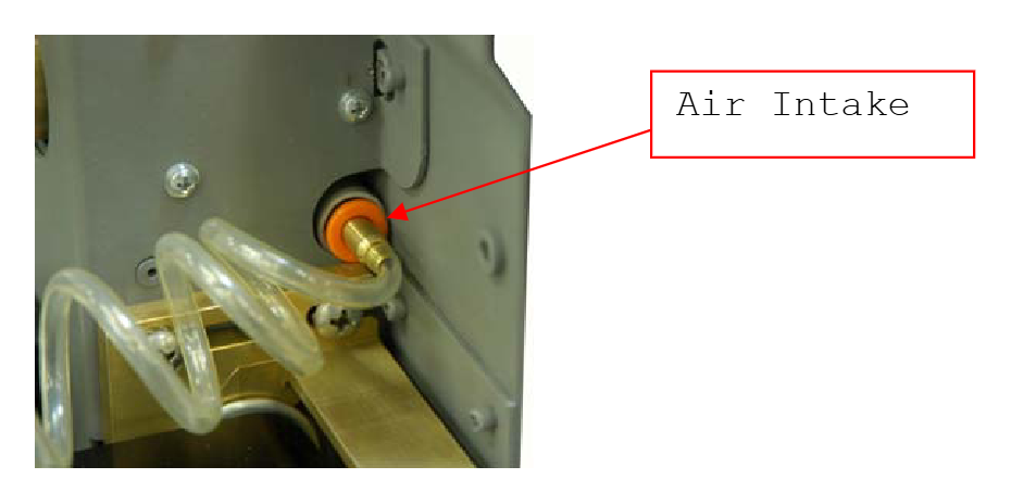
Disconnect the Air Intake
Push in the orange ring on the air intake fitting and pull out the air hose.
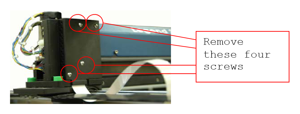
Remove the Amplifier Cover
Remove the four screws and the amplifier cover on the left end of the I-beam.
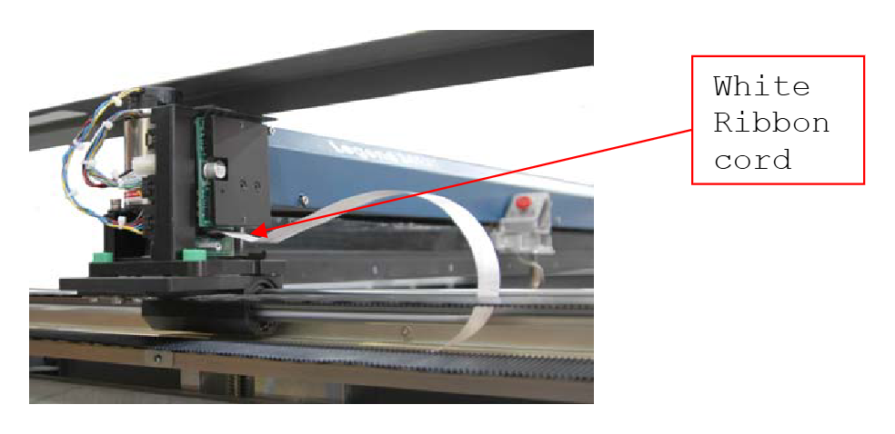
Disconnect the Ribbon Cable
The white ribbon cable plugs into the amplifier through a black connector. Press the lever under the connector with your index finger and pull the ribbon cable down to release it.
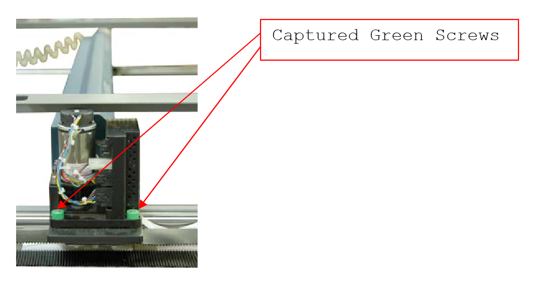
Loosen the Left Captive Screws
Loosen both green captive screws on the left end of the I-beam.
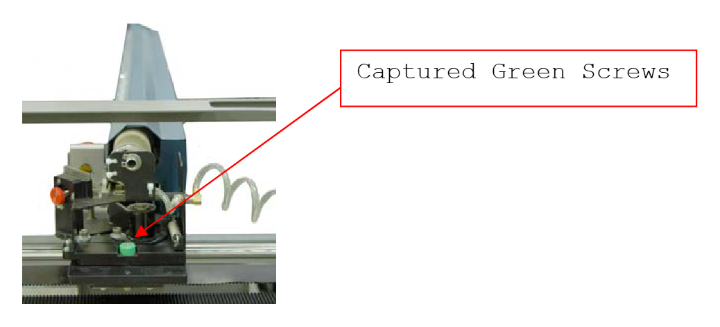
Loosen the Right Captive Screw
Loosen the single green captive screw on the right end of the I-beam.
Lift Out the I-Beam
Hold the I-beam in the center and lift it up and out.
Important: Lift the left end carefully so the X-axis motor clears the frame rail above the I-beam.
I-Beam Installation
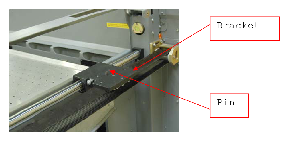
Set the I-Beam in Place
Set the new I-beam in exactly as the old one came out. It sits on black brackets with locating pins; make sure the I-beam is seated on the pins at both ends.
Check the Y-Axis Movement
Move the I-beam from front to rear a couple of times to check that the Y-axis moves smoothly.
Tighten the Captive Screws
Tighten the three green captive screws: two on the left end and one on the right.
Reconnect the Ribbon Cable
Push the white ribbon cable back into its connector on the amplifier.
Reinstall the Amplifier Cover
Reinstall the amplifier cover with its four screws.
Reconnect the Air Intake
Push the air hose back into the air intake fitting.
Reinstall the Side Panels
Reinstall both side panels, including the three rear screws on the left panel.
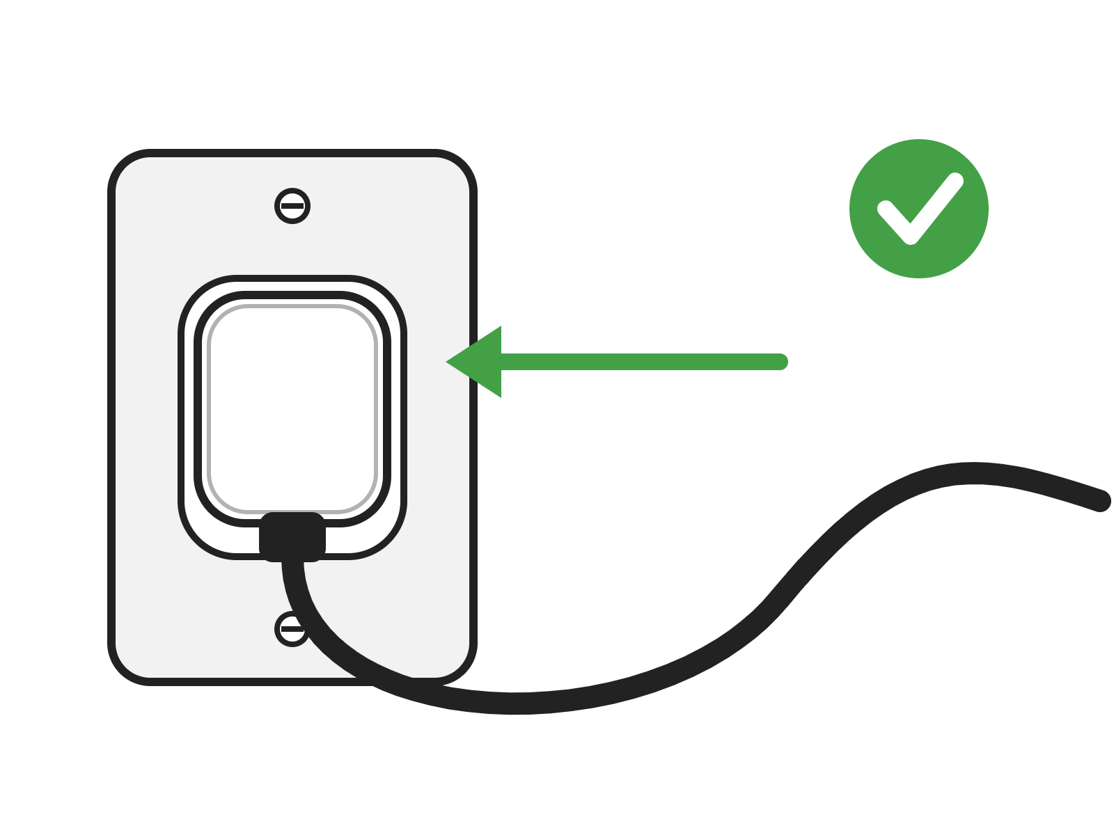
Reconnect Power
Plug the power cord back in and turn on the engraver.