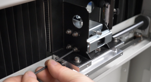
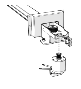
This guide covers replacing the x-axis idler pulley on the Fusion Pro 32 and 48. The idler is on the left end of the x-axis assembly. After installation, the x-axis belt is re-tensioned using the motor’s RMS current reading.
Parts Required
- CS0416 – Assy, Pulley, Idler, X-Axis
Tools Required
- 5/32", 7/64" and 3/32" Allen Wrenches
Safety First: Ensure the engraver is completely powered off and the power cord is disconnected before removing any panels or touching internal components.
X-Axis Idler Removal
Turn Off Engraver
Turn off the engraver.
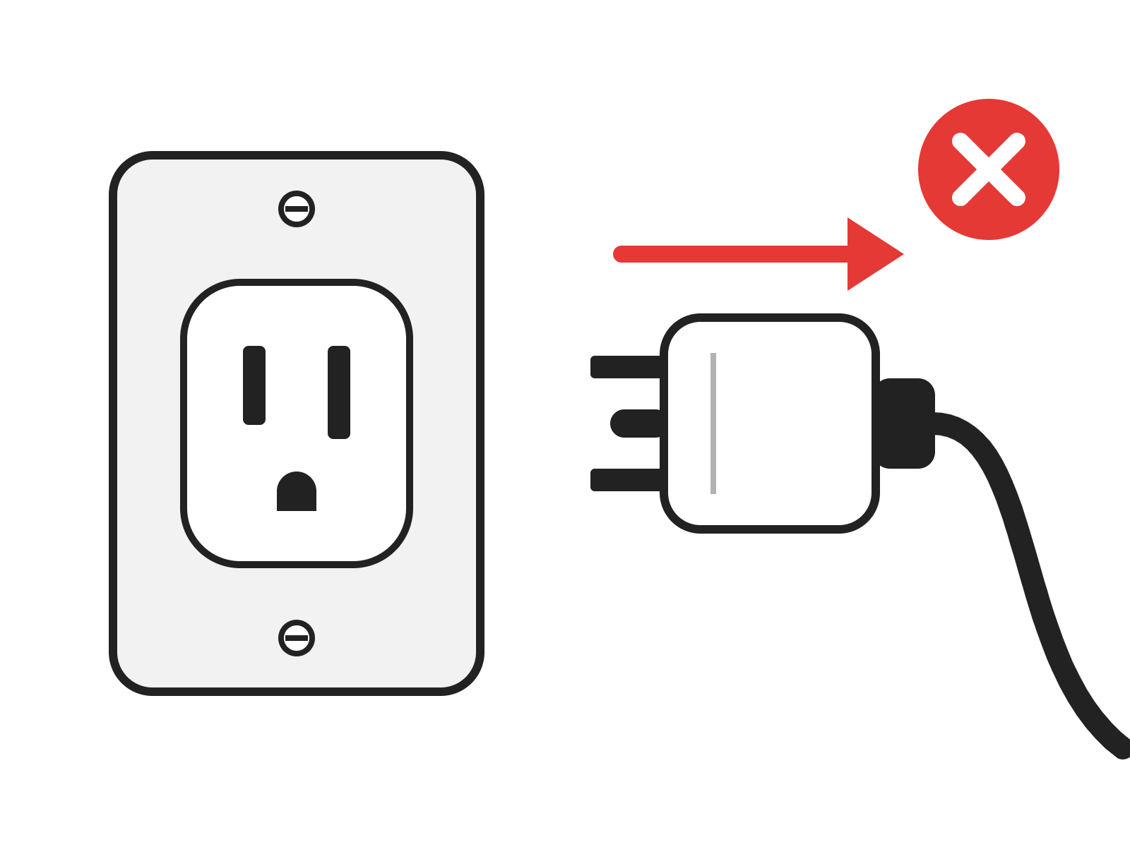
Disconnect from Power
Unplug the engraver from its power source.
Remove Left Panel
Remove the left panel of the engraver.
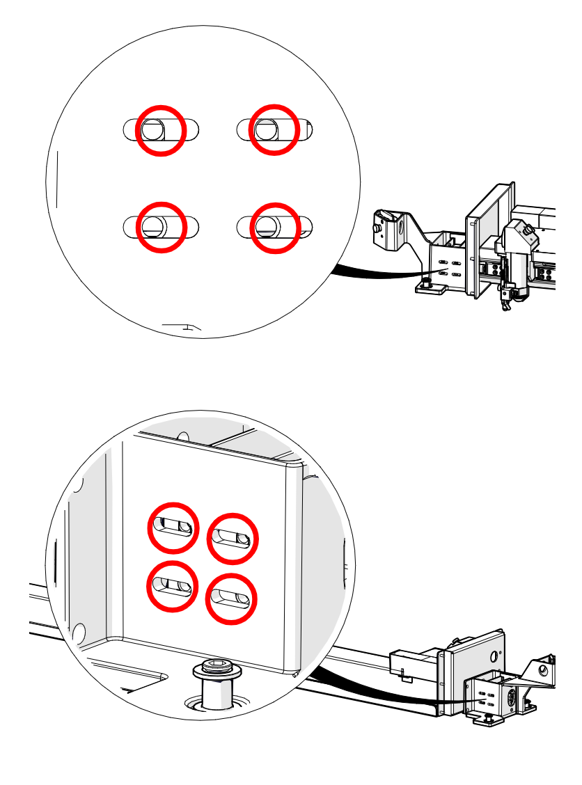
Loosen Idler Mounting Screws
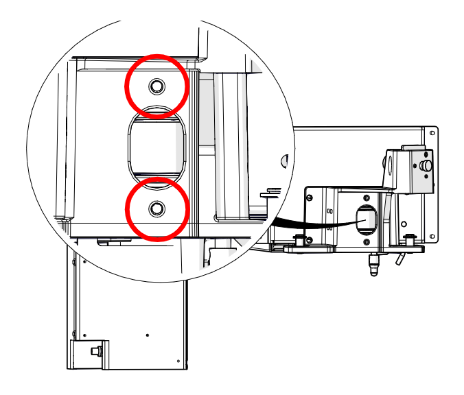
Loosen, but do not remove, the eight 7/64" idler mounting screws on the left side of the x-axis assembly (circled in red).
Release Belt Tension
Remove the tension from the x-axis belt by loosening the two 7/64" screws on the idler assembly body (circled in red).
Remove Upper Screws
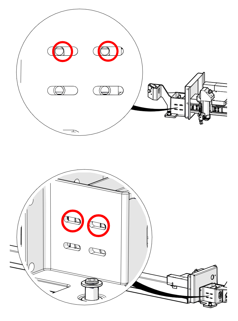
Remove the upper two 7/64" screws from both the front and the rear of the x-axis assembly (circled in red).
Remove Tensioner Bracket
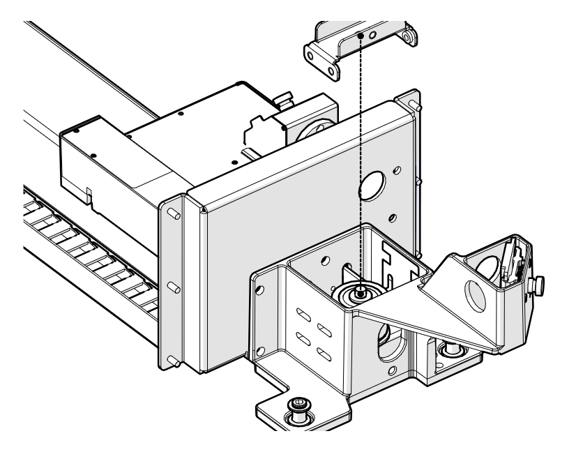
Remove the upper tensioner bracket.
Remove Upper Washer
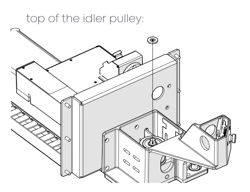
Remove the Delrin washer from the top of the idler pulley.
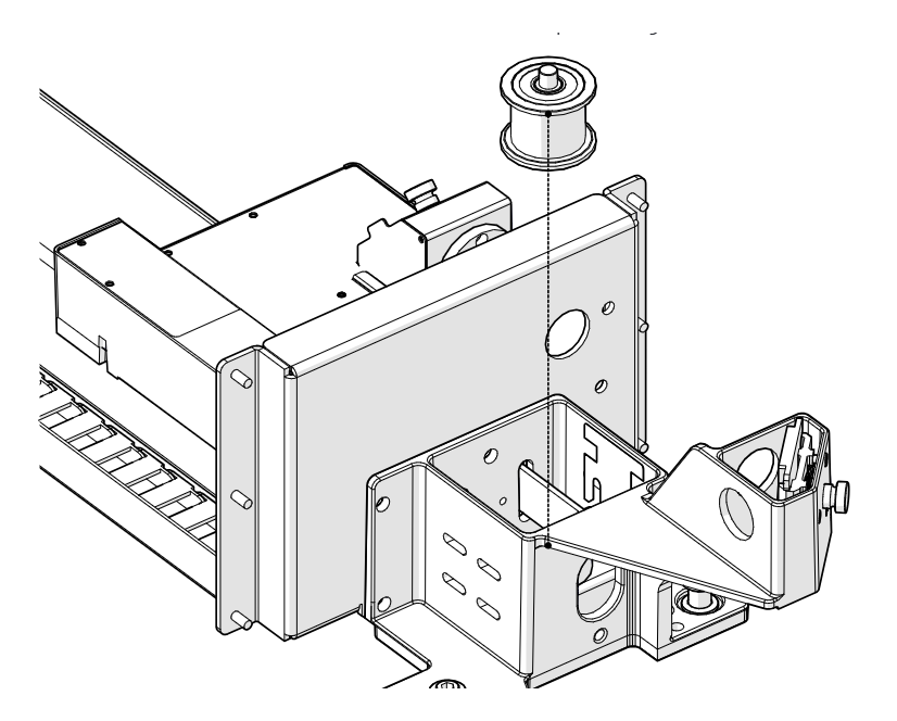
Remove the Idler Pulley
Remove the x-axis idler pulley.
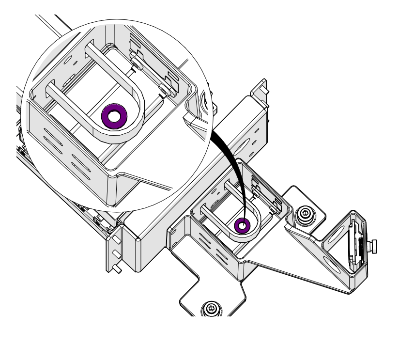
Check the Lower Washer
Make sure the lower Delrin washer (highlighted in purple) is still in place.
X-Axis Idler Installation
Install the New Idler Pulley
Install the new CS0416 x-axis idler pulley.
Install Upper Washer
Install the Delrin washer on top of the idler pulley.
Install Tensioner Bracket
Install the upper tensioner bracket.
Install Upper Screws
Install, but do not fully tighten, the upper two 7/64" screws on the front and rear of the x-axis assembly.
Tensioning the X-Axis Belt
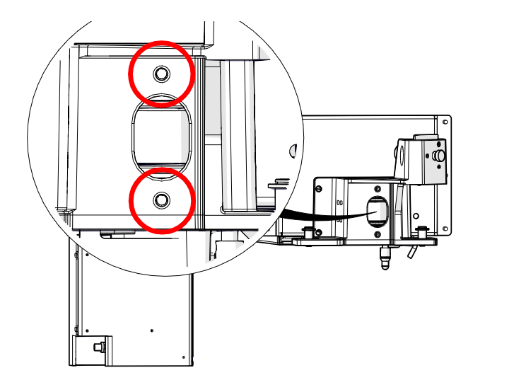
Tension the X-Axis Belt
Apply tension to the x-axis belt with the two 7/64" belt tensioning screws (circled in red) until the excess slack is removed.
Power On
Reconnect the engraver to power and turn it on.
Create a Test Box
In your preferred illustration program, create a black raster box on the artboard that is:
- Fusion Pro 48: 46" (1100 mm) wide
- Fusion Pro 32: 30" (800 mm) wide
- Roughly 4" (100 mm) tall
Print the Job
Print to the Epilog Software Suite or Epilog driver with these settings:
- Speed: 100
- Power: 0
Note: Power does not matter here, as the engraver runs with the lid open for this procedure.
Start the Job
Send the job to the engraver and start it.

Open the Settings Menu
On the display, press the gear icon in the upper right corner to open the Settings menu.
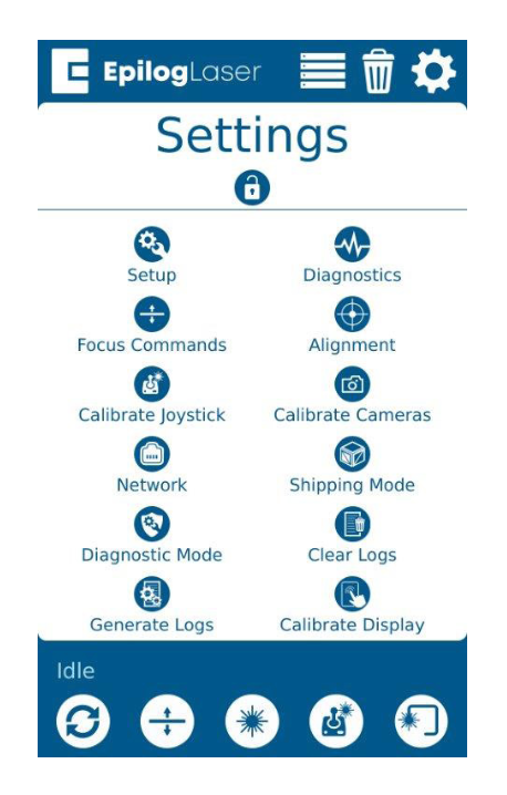
Open Advanced Settings
Press and hold the word Settings on the display to open the Advanced Settings menu.
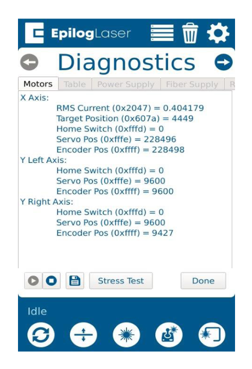
Find the X-Axis RMS Current
Open the Diagnostics menu and find the RMS Current reading for the X-Axis motor/drive.
Adjust to 4.5 – 6.2 A
While the job runs, the x-axis motor RMS current should be between 4.5 and 6.2 A.
- If the current is lower, increase belt tension by tightening the two 7/64" tensioner screws on the x-axis idler assembly.
- If the current is higher, decrease belt tension by loosening the two 7/64" tensioner screws.
Note: If the current cannot be brought above the lower limit, the belt may need to be trimmed: remove two teeth with aviation or metal snips and repeat the tensioning. If it cannot be brought below the upper limit, other mechanical issues may be affecting the lens carriage travel. Check the x-axis belt clamp placement and the x-axis reducer belt tension, and look for physical obstructions or wear points.
Check Engraving Quality
The RMS current range is a guideline, not the only reference for belt tension. Once the current is in range, engrave a line of capital "T"s in Times New Roman and inspect the serifs:
- Good tension: the serifs are well defined.
- Loose belt: the serifs look doubled or skewed.
- Tight belt: the engraver may be noisier than usual and show error messages.
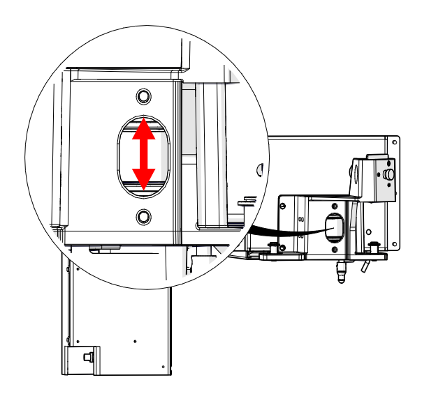
Check Belt Tracking
With the belt tensioned, check that the x-axis belt stays as centered as possible on the idler pulley while in motion.
Center the Belt
If the belt rides against the idler pulley flange, make equal but opposite adjustments to the two 7/64" tensioner screws. Repeat until the belt stays centered on the pulley in motion.
- Belt too high: tighten the top screw 1/4 turn and loosen the bottom screw 1/4 turn.
- Belt too low: loosen the top screw 1/4 turn and tighten the bottom screw 1/4 turn.
Tighten Idler Mounting Screws
Once the belt is centered and the RMS current is in range, tighten the eight 7/64" idler mounting screws on the left side of the x-axis assembly.
Install Left Panel
Install the left panel of the engraver.