
This guide provides step-by-step instructions for removing and replacing the top door assembly on an Epilog Ascent laser machine.
Power Safety: Always turn off and unplug the machine before starting any service or disassembly work.
Top Door Replacement
Follow these steps to safely disconnect, remove, and install a new top door on your system.
Power Down Machine
Turn off and unplug your machine to ensure complete electrical safety.
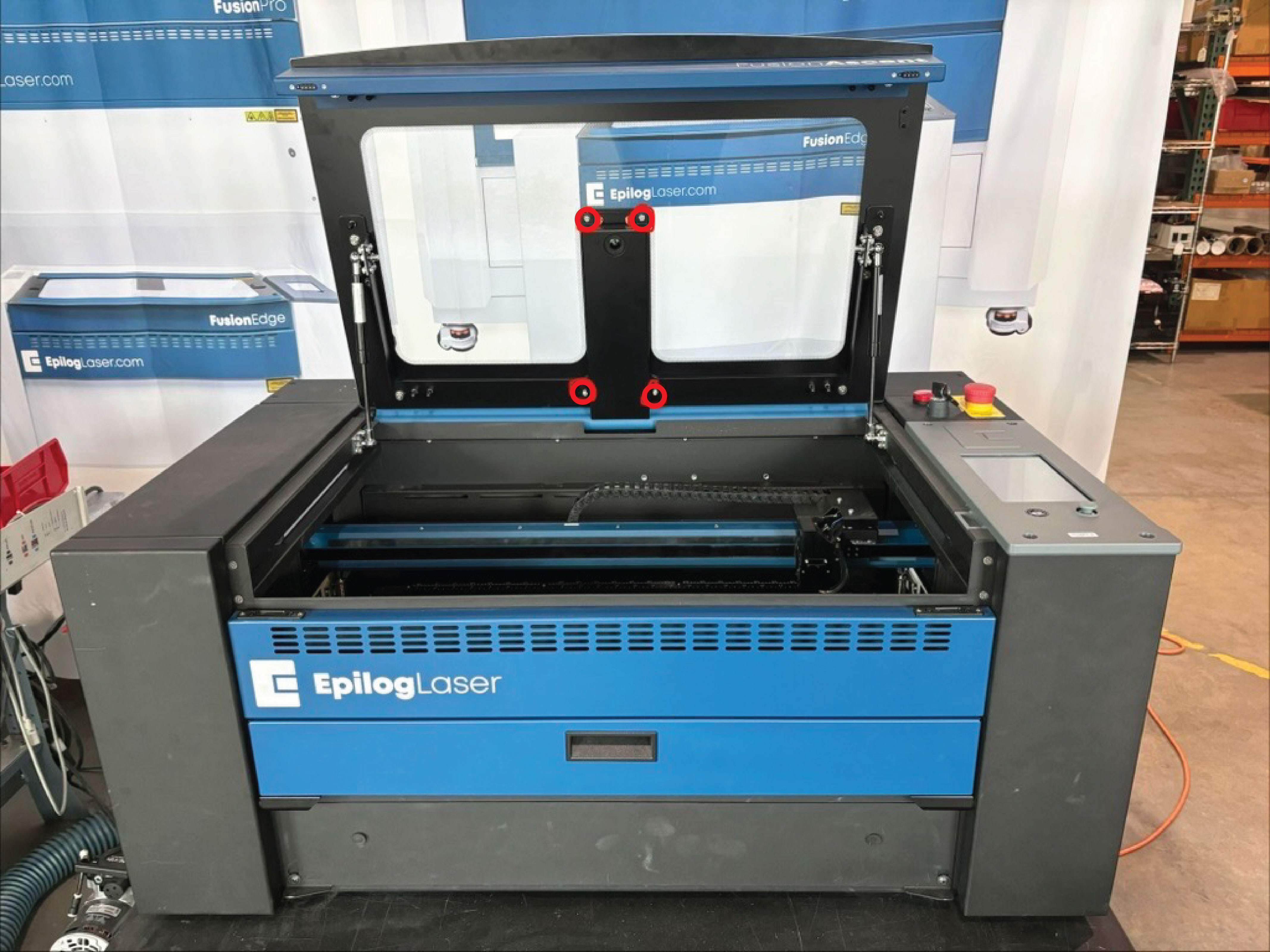
Remove Camera Cover
Unscrew and remove the 4 or 6 nuts securing the camera cover.
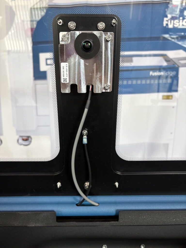
Document Harness Connections
Take a photo of the wiring harness layout to reference during reassembly.
Note: The reference photo shows an Ascent 12. Ascent 24 and 36 models will look different.
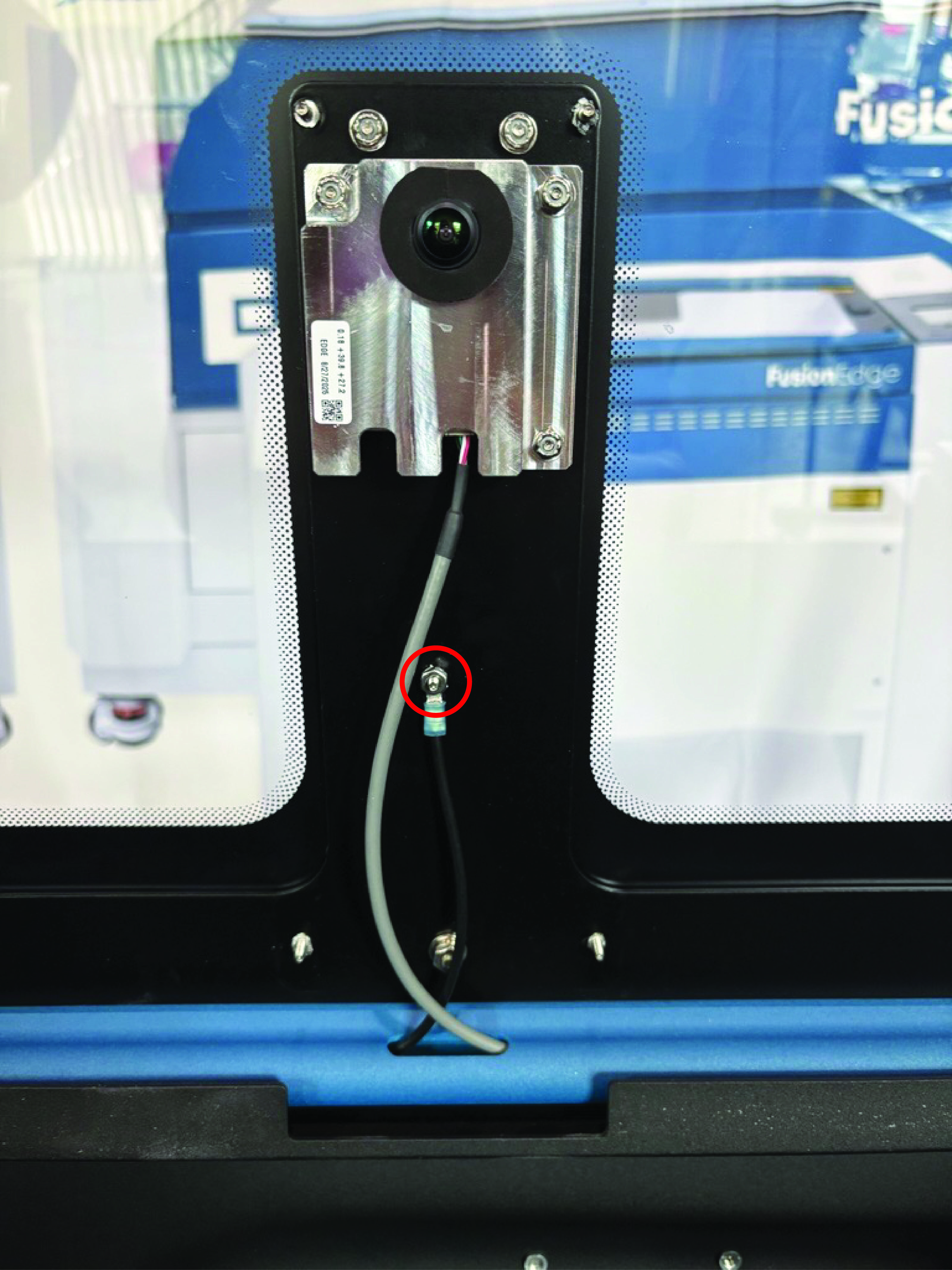
Remove Ground Harness
Loosen and remove the ground harness connector.
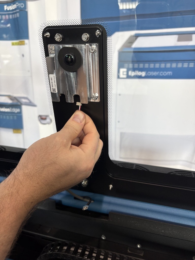
Disconnect Camera Cables
Unplug the camera cable connectors.
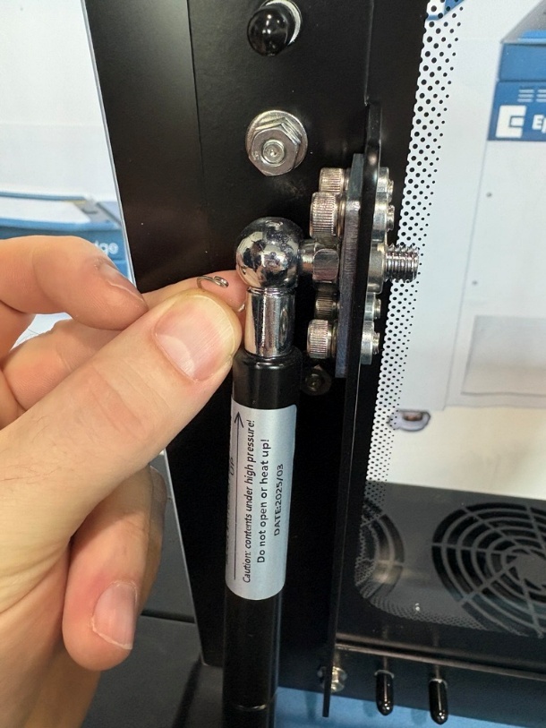
Remove Shock Clips
Remove the gas shock retaining clips located at the top door.
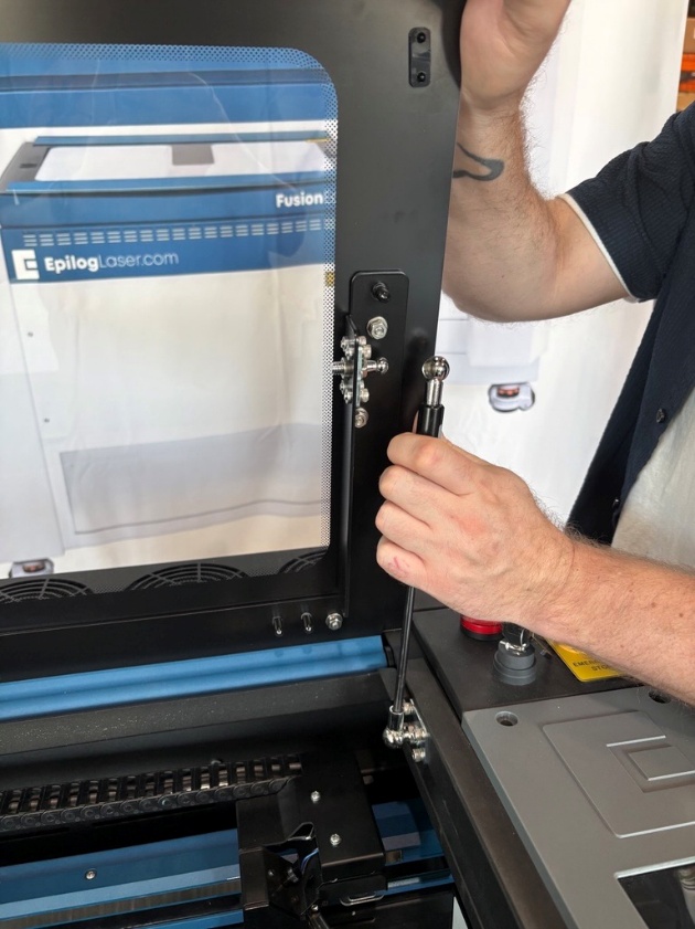
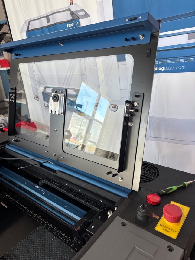
Detach Gas Shocks
With two people, simultaneously detach the gas shocks from both sides and gently rest the door at the back of its travel.
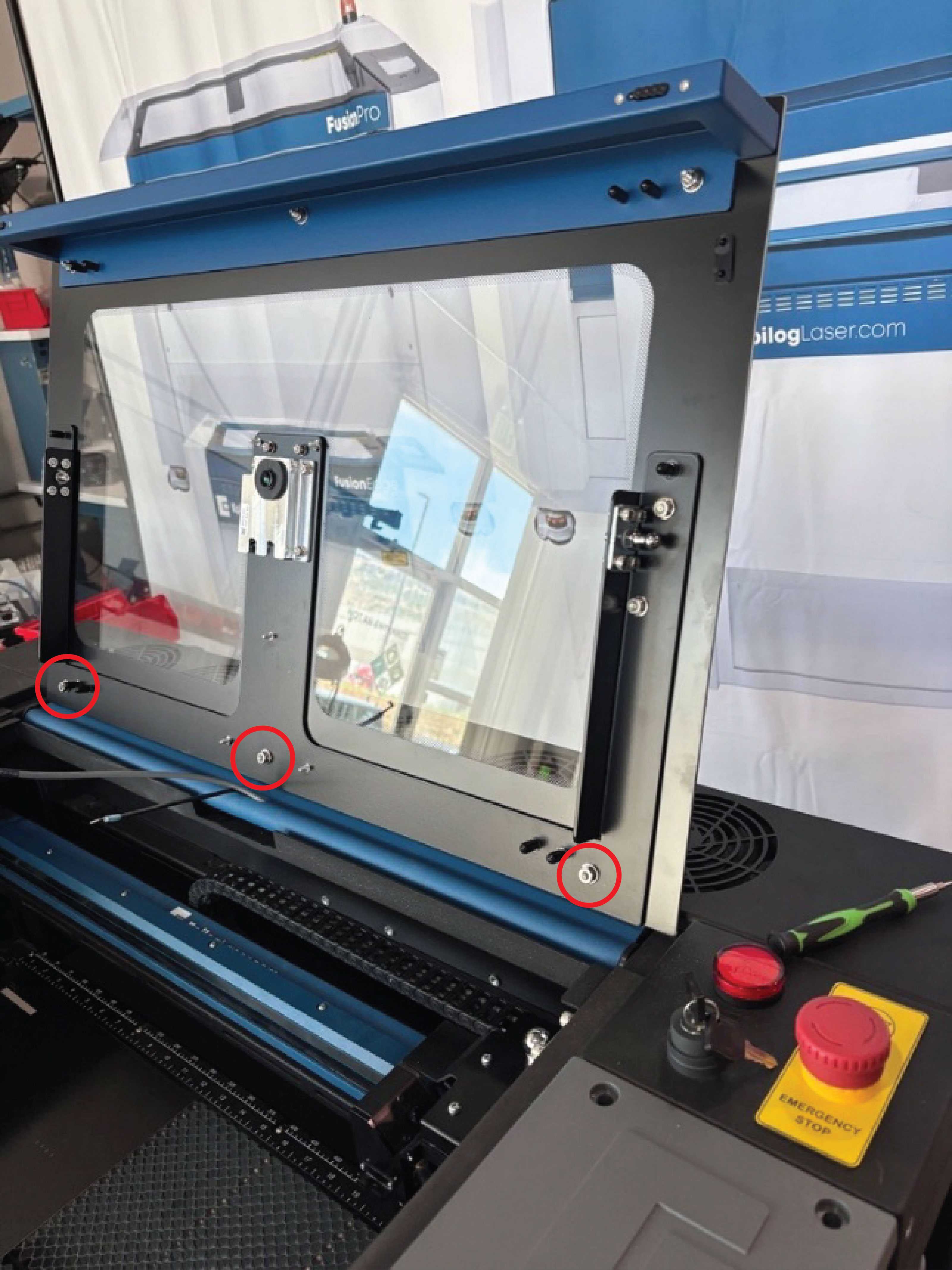
Remove Lid Base Nuts
Have one person support the top door while another loosens and removes the three lid base nuts.
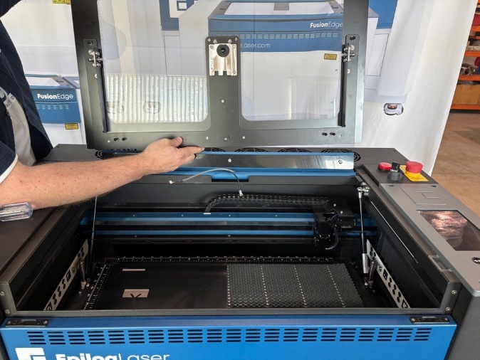
Slide Off Old Door
Carefully slide the top door forward and off of the base posts.
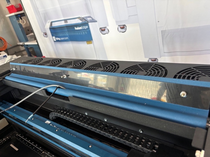
Verify Shim and Spacers
Ensure the black shim along the hinge bar and the three white spacers (one per post) remain in place.
Position New Top Door
Working with a partner, carefully slide the new top door onto the three base posts.
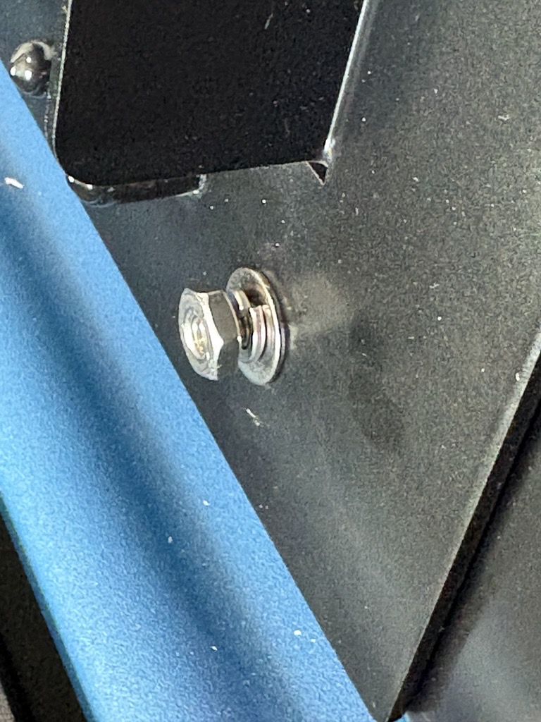
Secure Door Base Posts
While supporting the door, install a washer, lock washer, and nut onto each post. Do not overtighten.
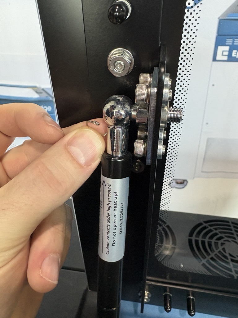
Reattach Gas Shocks
Reattach each gas shock post and secure them with their respective retaining clips.
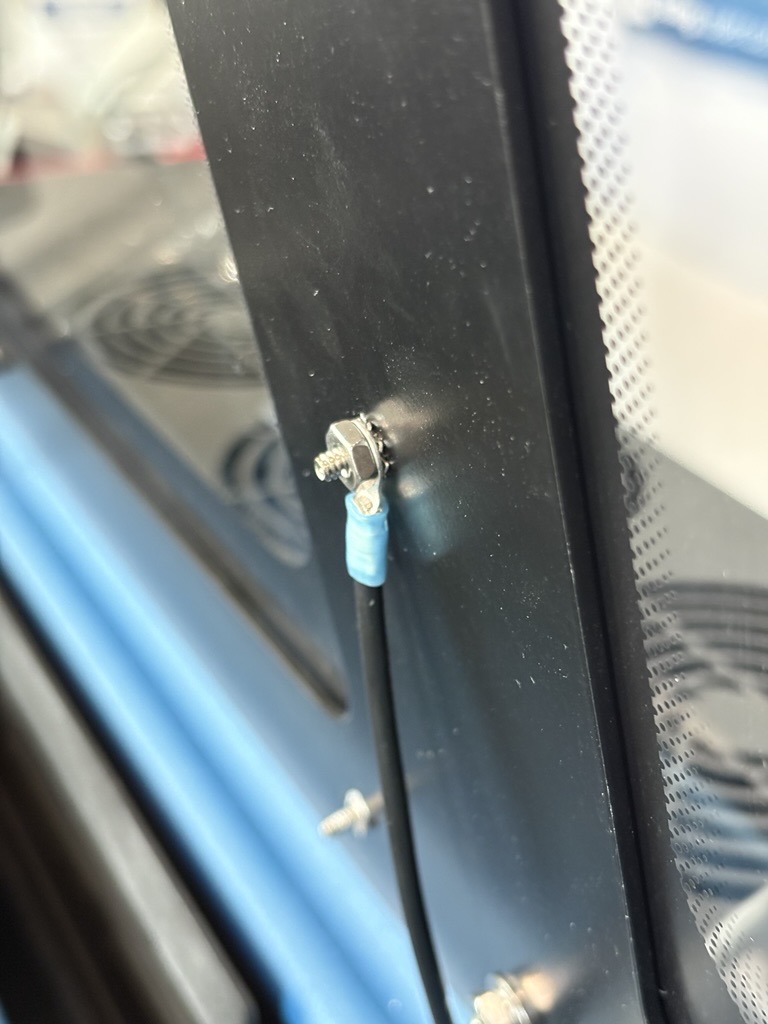
Reconnect Ground Harness
Connect the ground harness using the star washer first, followed by the ground ring, and then the nut.
Reconnect Camera Harness
Plug the camera harness cables back in.
Reinstall Camera Cover
Attach the camera cover and secure each of the 4 or 6 posts with a lock nut.
Camera Calibration Required
Once installation is complete, perform the camera calibration procedure specific to your machine model before resuming operations.