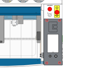
La seguridad es lo primero: Asegúrate de que el sistema láser esté completamente apagado y de que el cable de alimentación principal esté desconectado de la toma de corriente antes de tocar o desconectar cualquier componente electrónico interno. No toques ningún componente expuesto de la fuente de alimentación.
Importante: La placa de control, la placa base y otros componentes electrónicos son sensibles a las descargas electrostáticas (ESD). Utilice siempre una muñequera antiestática conectada a tierra al chasis metálico desnudo de la máquina antes de manipular estos componentes para evitar daños.
Parte 1: Desmontaje de la placa de control
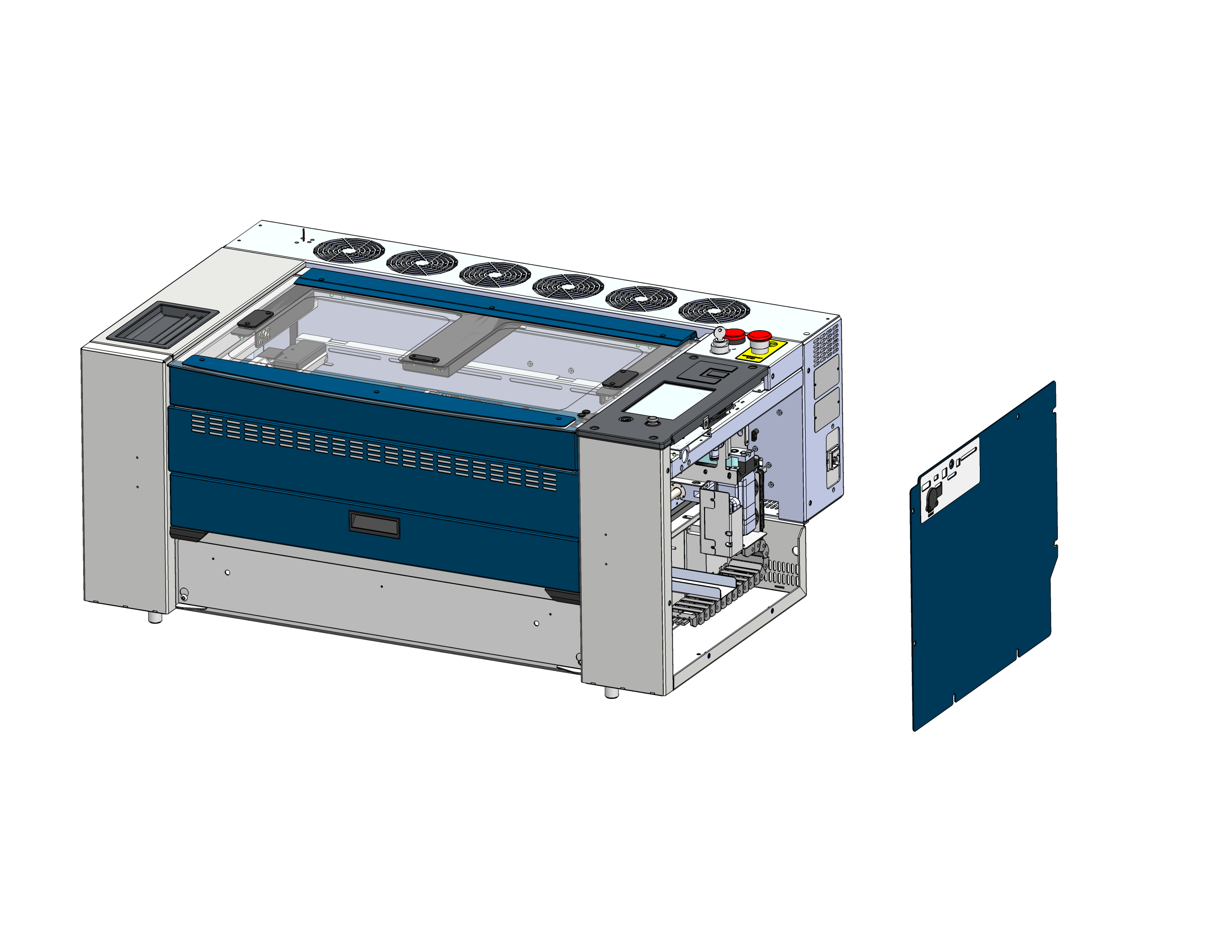
Quitar panel lateral
Localiza y retira el panel lateral derecho del chasis del láser para acceder a los componentes electrónicos.
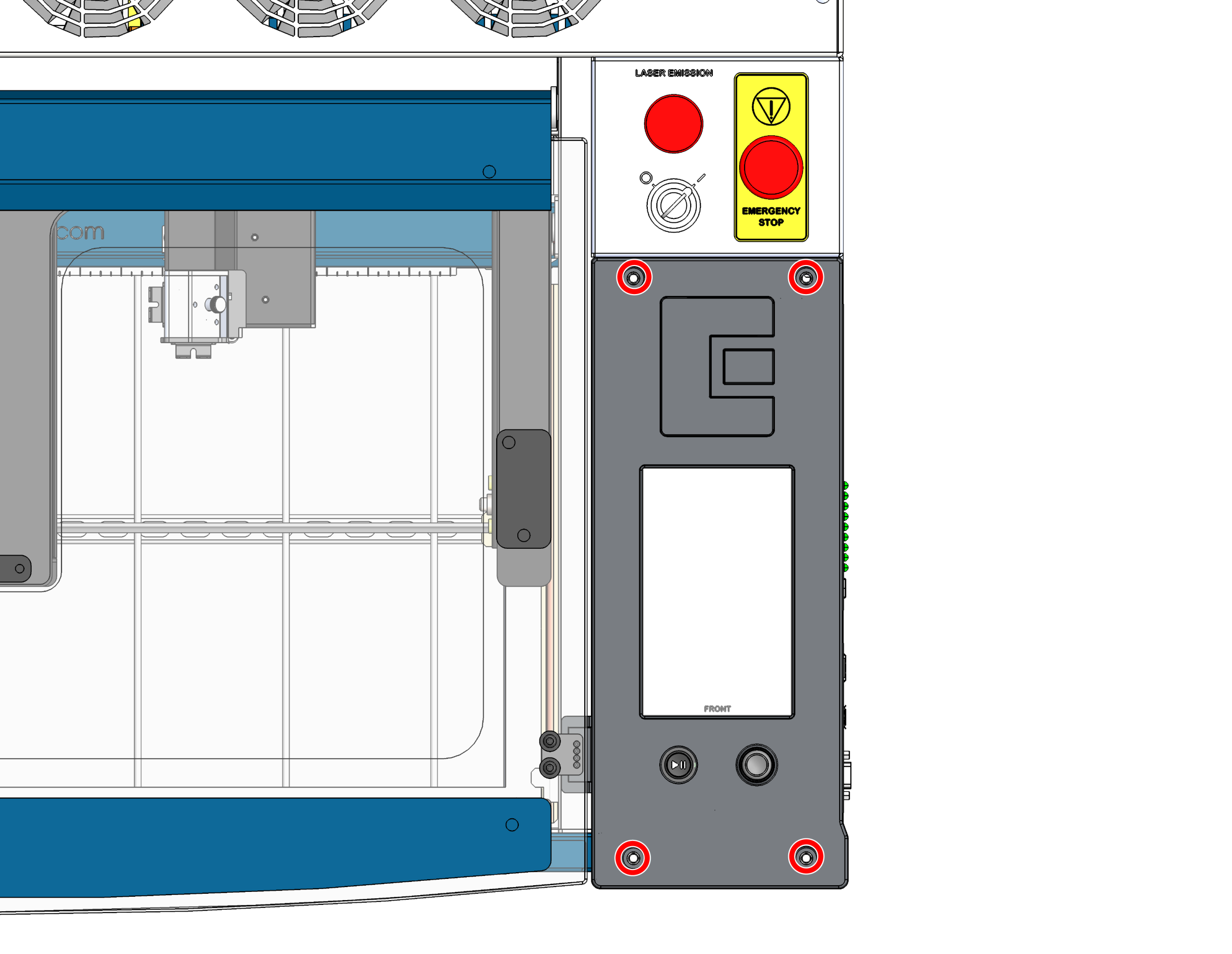
Quita los tornillos de la placa de control
Quita los 4 tornillos que fijan la placa de control al chasis.
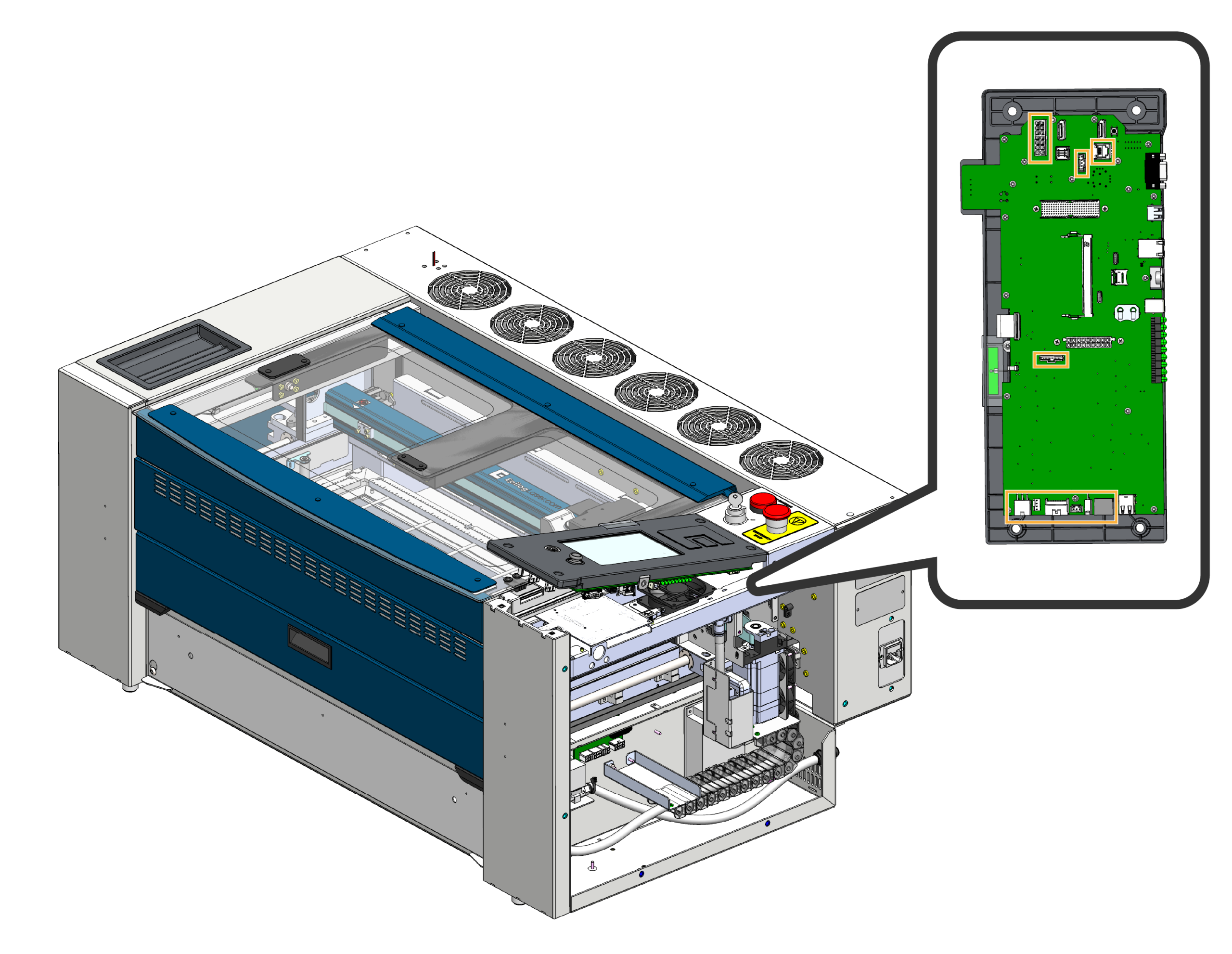
Desconectar el arnés
Levante con cuidado la parte delantera de la placa de control y desconecte los mazos de cables que están enchufados a ella.
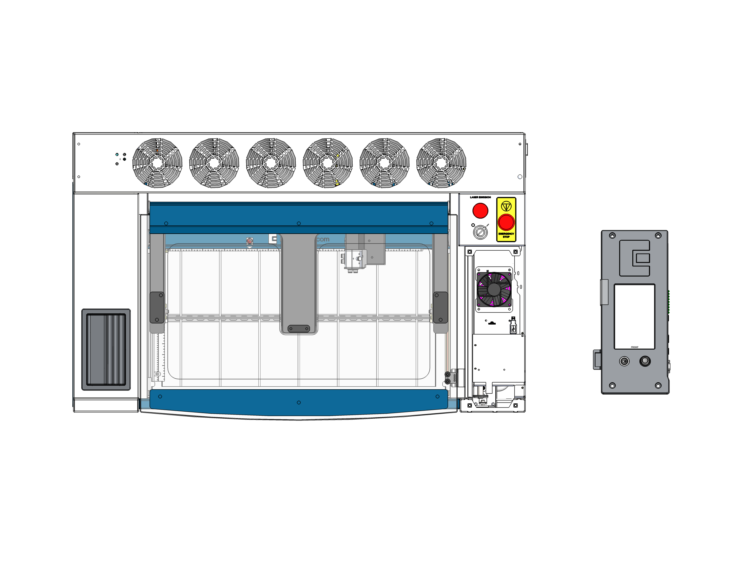
Retirar la placa de control
Desmonta y retira por completo la placa de control de la máquina. Colócala boca abajo sobre una superficie segura y libre de electricidad estática. Importante: Asegúrate de que la palanca de mando cuelgue por el borde de la superficie o esté apoyada sobre un material blando, para que no se aplaste ni se dañe mientras trabajas en la parte trasera de la placa.
Parte 2: Sustitución de la tarjeta SD y la pila de botón
Con la placa de control colocada de forma segura boca abajo, ahora puedes acceder fácilmente a la tarjeta SD y a la pila de botón que se encuentran en la placa y sustituirlas.
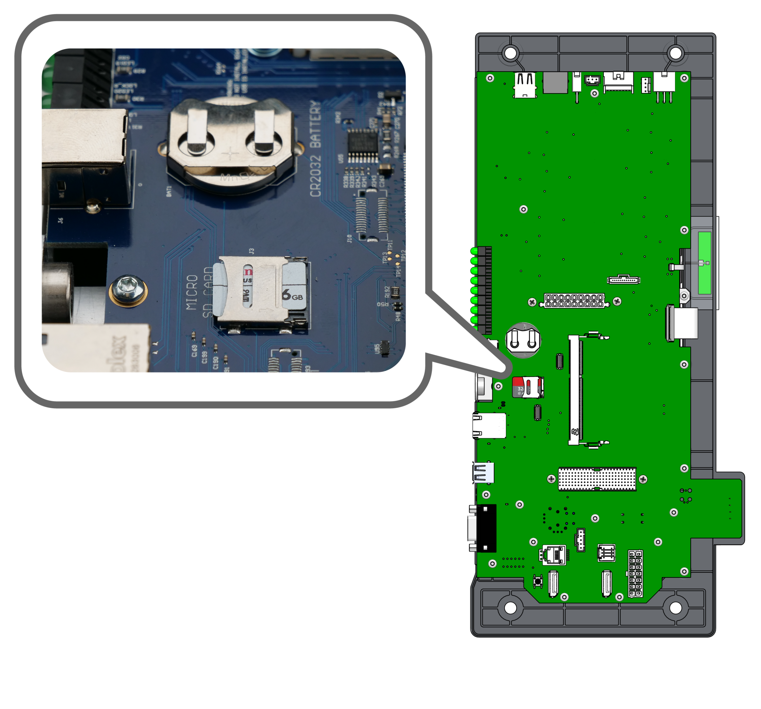
Localizar componentes
Localiza la tarjeta micro SD y el compartimento de la pila de botón CR2032 en la parte trasera de la placa de control.
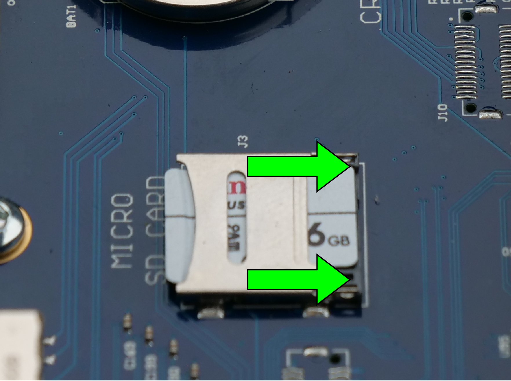
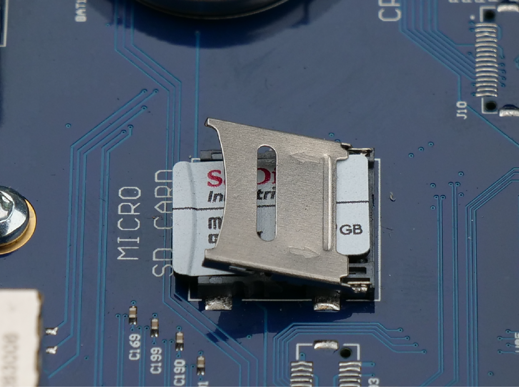
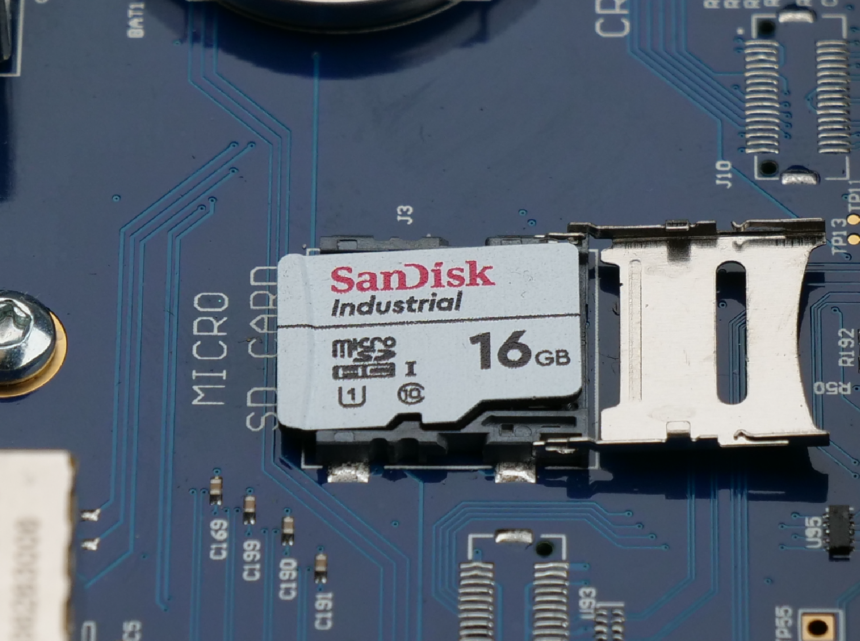
Sustituir la tarjeta SD
Haz clic en las pestañas de las imágenes para ver los pasos de sustitución:
- Para desbloquear: Desliza el pestillo metálico hacia dentro (en la dirección de la flecha) para desbloquearlo.
- Para abrir: Levanta el pestillo metálico desbloqueado para dejar al descubierto la tarjeta SD.
- Sustitución: Retira la tarjeta SD antigua, inserta la nueva y, a continuación, cierra el cierre y deslízalo hacia fuera para bloquearlo en su sitio.
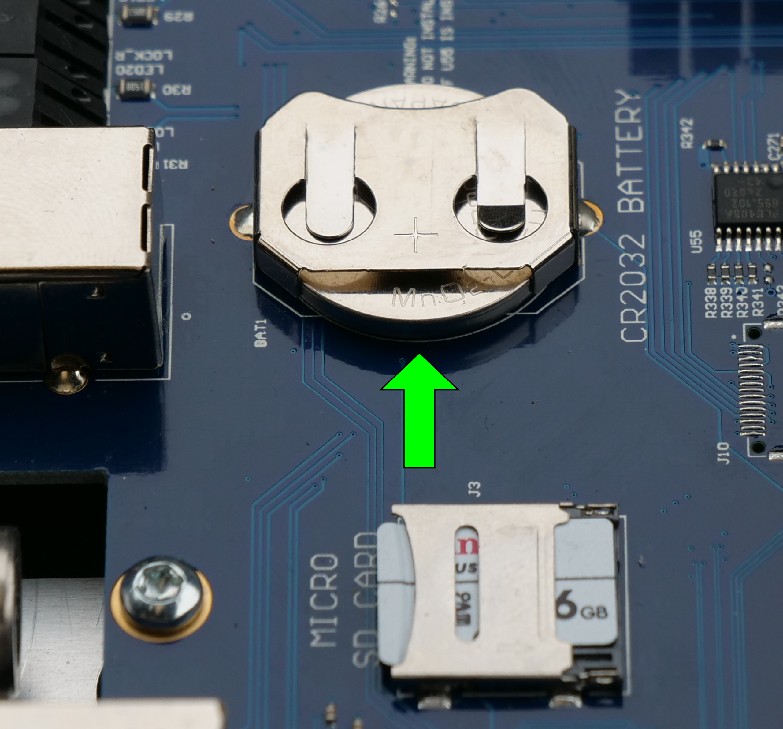
Sustituir la pila de botón
Localiza el compartimento de la pila de botón en la placa de control. Desliza con cuidado la pila antigua para sacarla de su clip de sujeción. Inserta la pila nueva con el polo positivo (+) hacia arriba.
Parte 3: Sustitución de la placa base
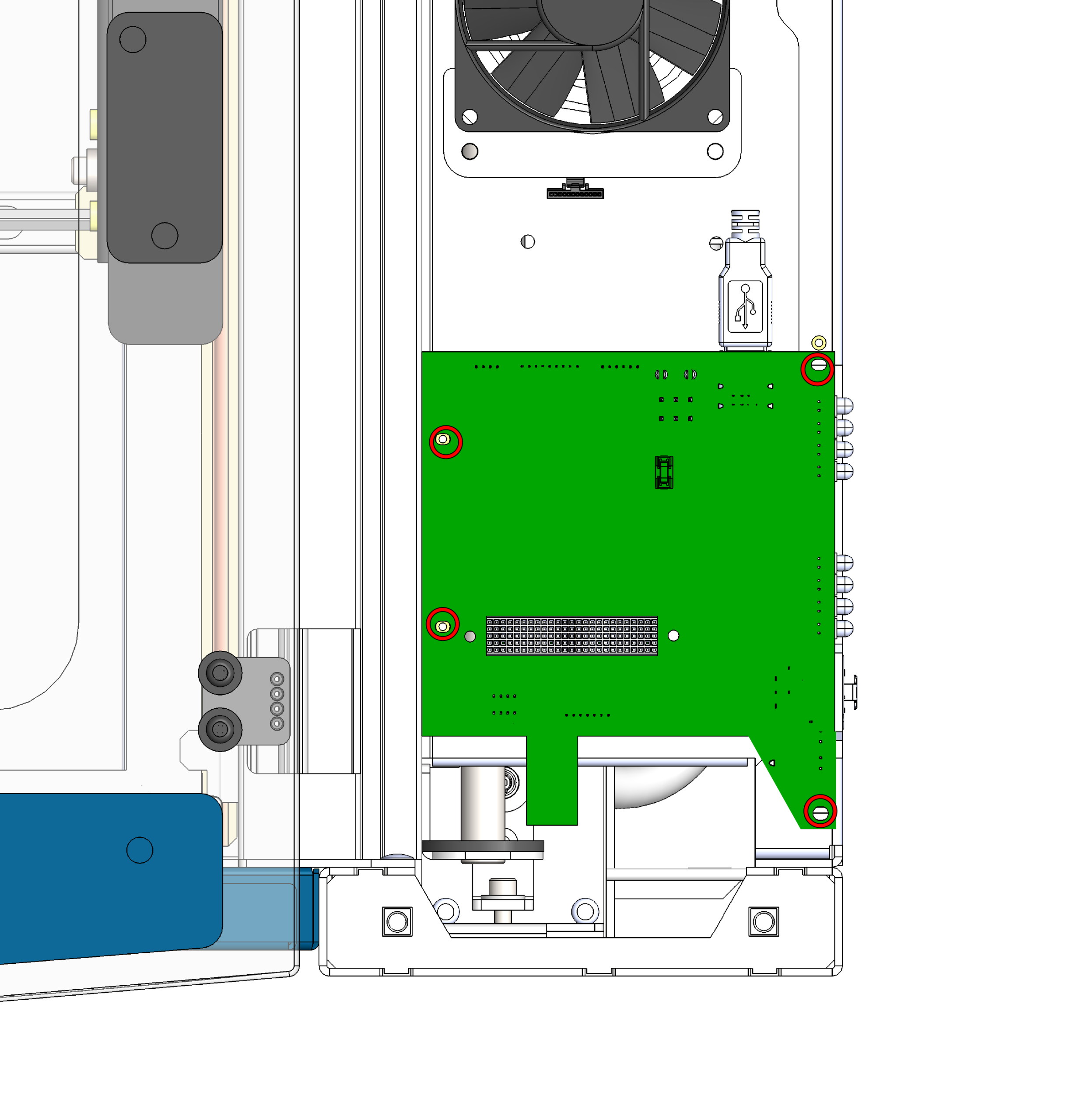
Quitar los tornillos de la placa base
Localiza la placa de base, situada debajo de la placa de control, y retira los cuatro tornillos que la fijan al chasis.
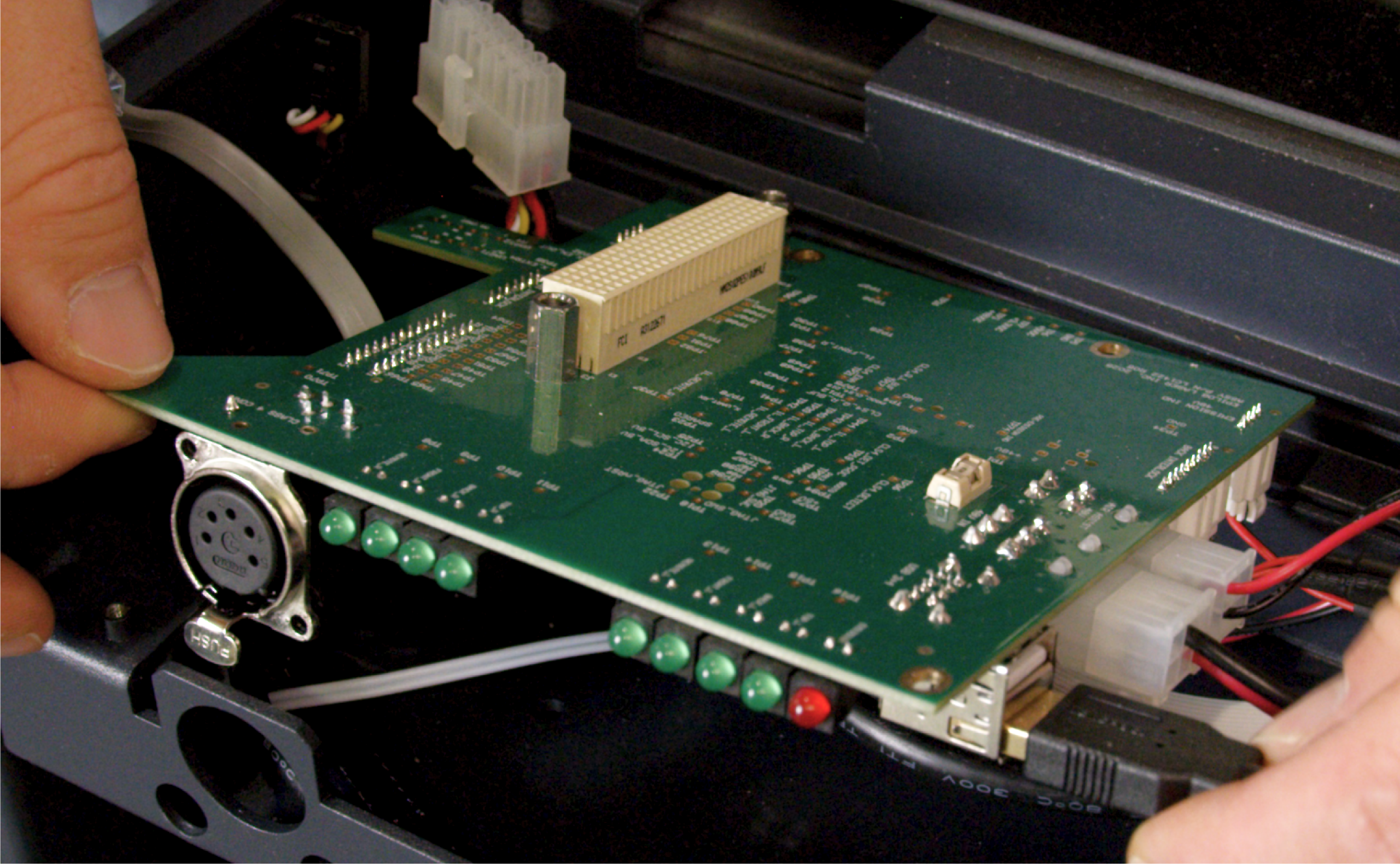
Desconectar los cables
Una vez desenroscada la placa, desconecta con cuidado todos los mazos de cables y los cables que estén conectados a ella. Cuando lo hayas desconectado todo, saca la placa base de la máquina.
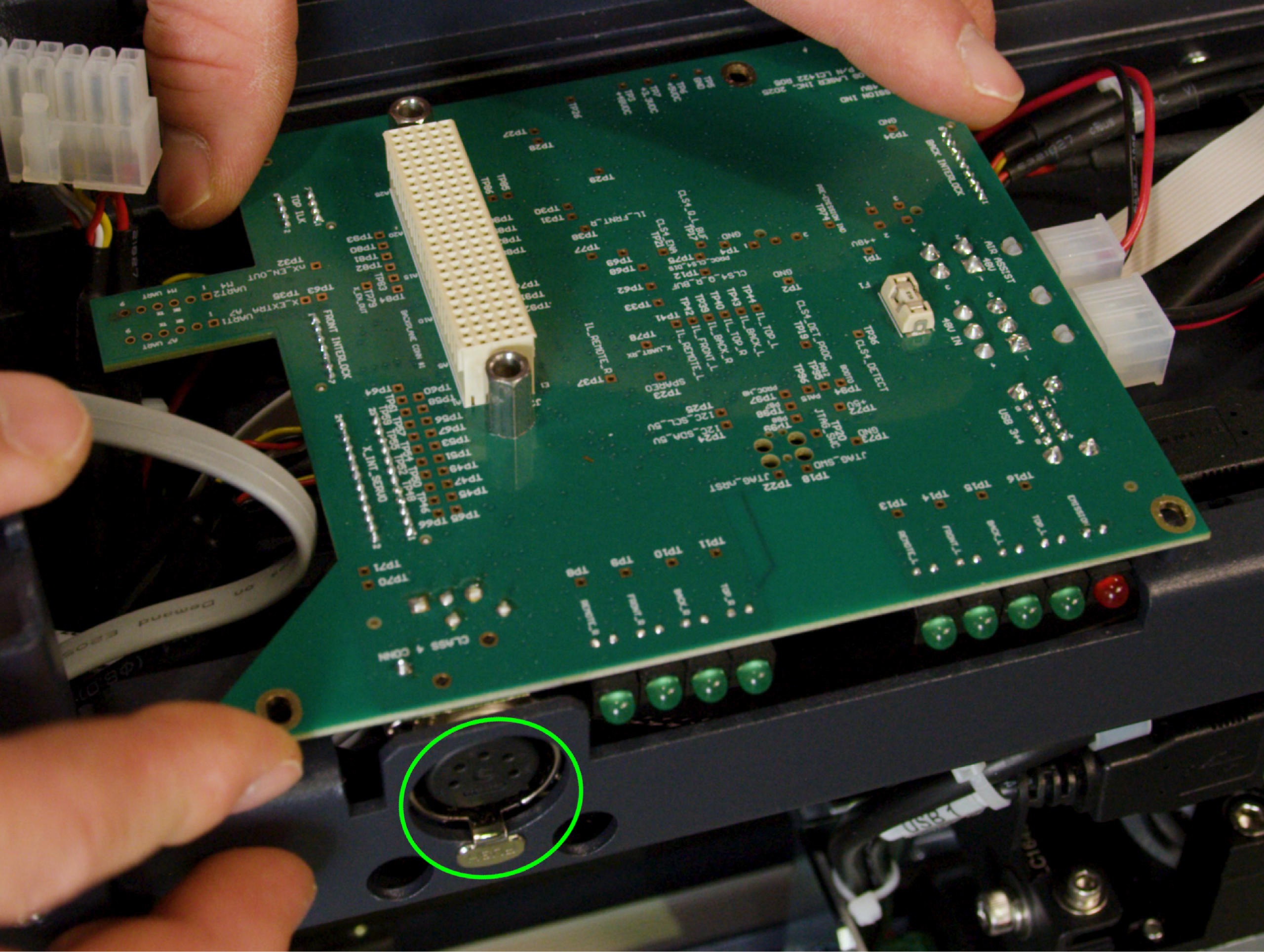
Instalar la placa base de recambio
En primer lugar, vuelve a conectar todos los cables que desconectaste en el paso 9. Una vez que todos los cables estén bien conectados, alinea la placa y vuelve a colocar los 4 tornillos para fijarla al chasis.
Importante: El puerto para el dongle de clase 4 tiene una lengüeta que debe alinearse con el hueco del chasis. Asegúrate de que la lengüeta quede correctamente encajada en el hueco antes de apretar los tornillos, para evitar dañar el puerto o la placa.
Parte 4: Montaje e instalación
Volver a conectar el mazo de cables de la placa de control
Acerca con cuidado la placa de control (con su nueva tarjeta SD y batería) a la zona de montaje y vuelve a conectar los mazos de cables a la placa.
Placa de control del asiento
Centra la placa de control justo encima de los orificios para los tornillos. Presiona hacia abajo de manera uniforme y firme para asegurarte de que la placa quede bien fijada a la placa base recién instalada.
Placa de control segura
Vuelva a colocar y apriete los 4 tornillos para fijar la placa de control, una vez colocada correctamente, al chasis.
Reemplazar panel lateral
Vuelva a colocar y fije el panel lateral derecho de la máquina.
Verificación final
Vuelve a enchufar el aparato a la toma de corriente y enciéndelo. Comprueba que la pantalla táctil se inicie con normalidad y que el aparato se inicialice correctamente, lo que indica que la nueva placa, la tarjeta SD, la batería y la placa base se comunican correctamente entre sí.