
This guide covers removing and installing the top door on the Fusion Pro 32 and 48. The door is held to the chassis by a hinge on each side, and the camera USB cables and a ground lead run through the right-hand hinge, so they must be routed out of the door before it can be removed.
Parts Required
- Replacement Top Door Assembly (Fusion Pro 32 or 48)
Tools Required
- 5/16″ Nut Driver
- 3/8″ Nut Driver
- 3/8″ Wrench
- T8 Torx or 5/64″ Hex Key
- Small Flathead Screwdriver (gas shock clips)
- An assistant to support the door
Safety First: Turn off the engraver and unplug it from power before starting. The top door is large and heavy – have an assistant support it whenever the gas shocks are removed and while lifting it off the machine.
Top Door Removal
Turn Off Engraver
Turn off the engraver.
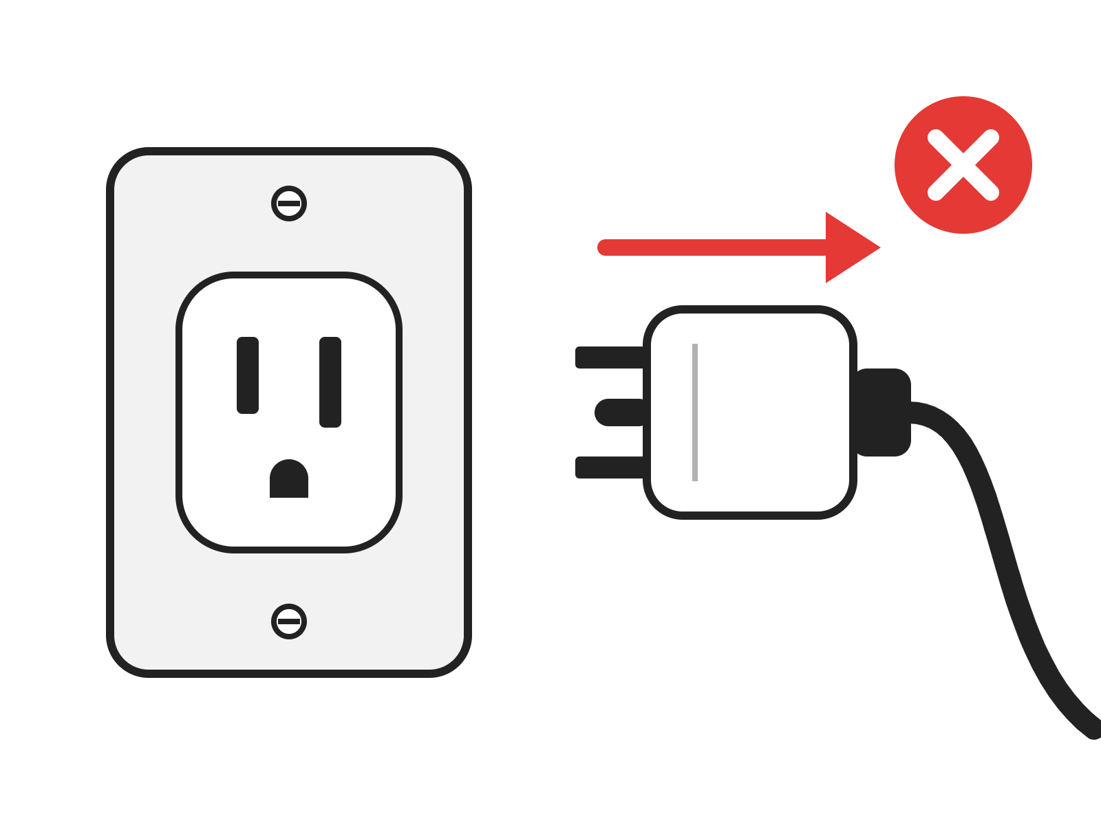
Disconnect from Power
Unplug the engraver from its power source.
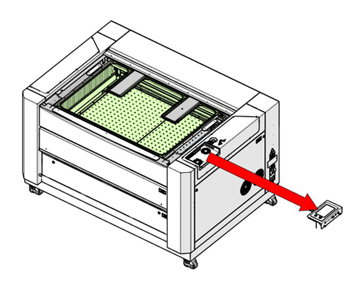
Remove the Control Assembly
Remove the control PCB assembly from the machine.
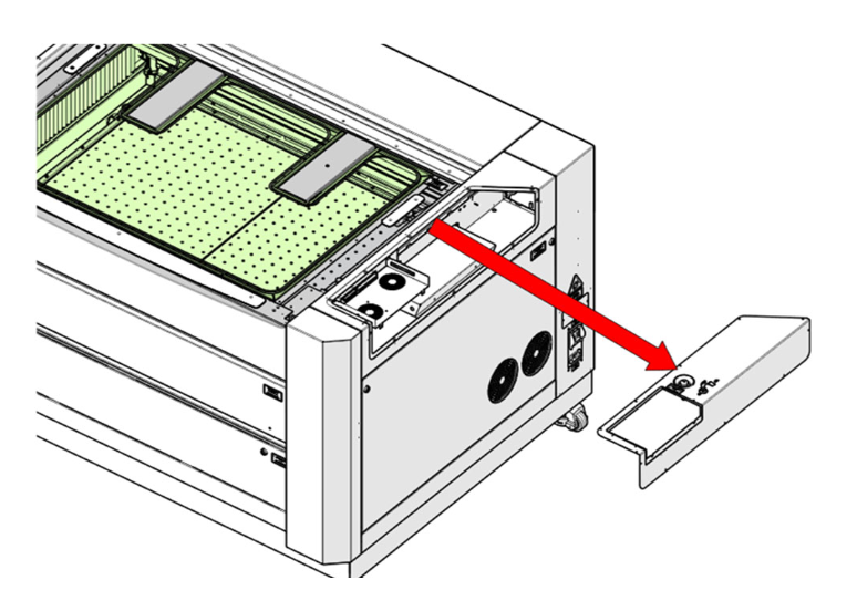
Remove the Right-Hand Bezel
Remove the blue bezel that surrounds the control PCB on the right-hand side of the machine.
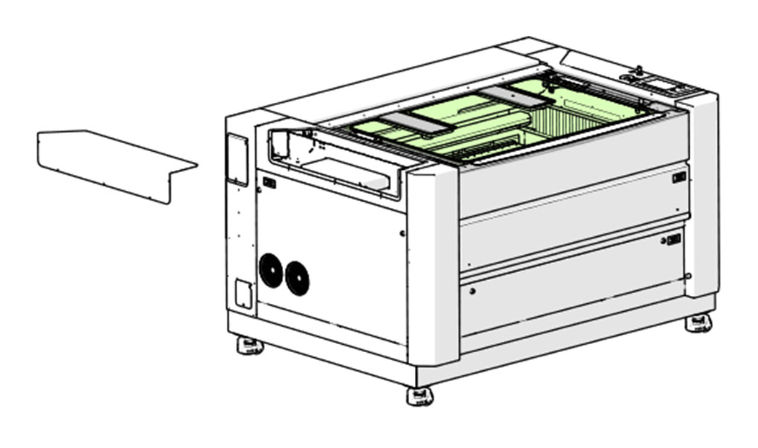
Remove the Left-Hand Bezel
On the left-hand side (facing the machine from the front), remove the left-hand blue bezel.
Open the Top Door
Open the top door.
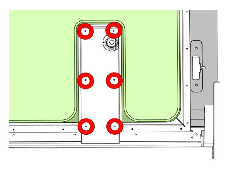
Remove the Camera Covers
Remove the screws (highlighted) and take the cover off each of the two camera assemblies.
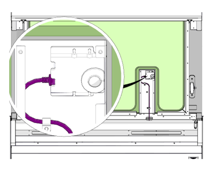
Disconnect the Camera USB Cables
Disconnect the USB cable from each of the two cameras.
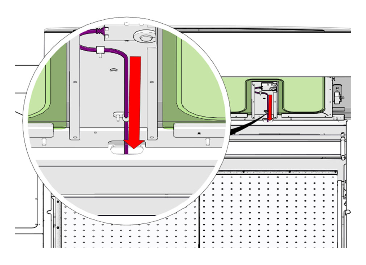
Push the Cables into the Door Slot
Push the USB cables down into the slot in the lower portion of the door.
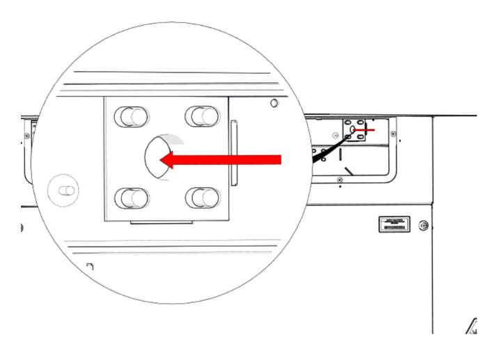
Pull the Cables Through the Hinge
Gently pull the cables out of the door through the right-hand side, where they exit through the door hinge.
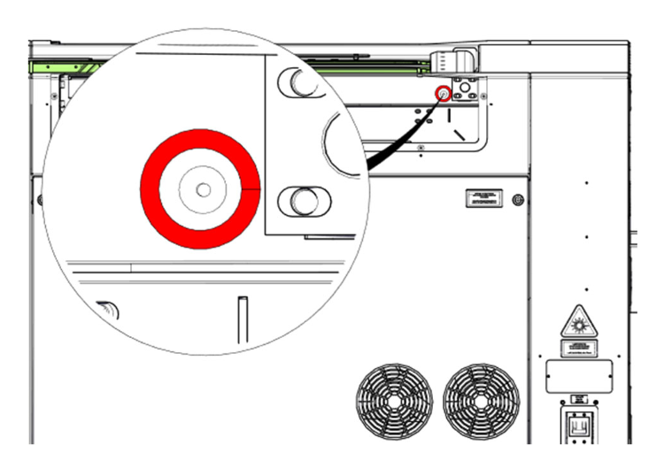
Remove the Ground Lead
On the right-hand side (facing the machine from the front), use a 5/16″ nut driver to remove the ground lead from the stud.
Remove the Gas Shocks and Lower the Door
With an assistant supporting the door, remove both gas shocks as described in the Top Door Gas Shock Replacement article, then lower the top door.
Important: The top door can drop once the gas shocks are removed. Keep it supported until it is fully lowered.
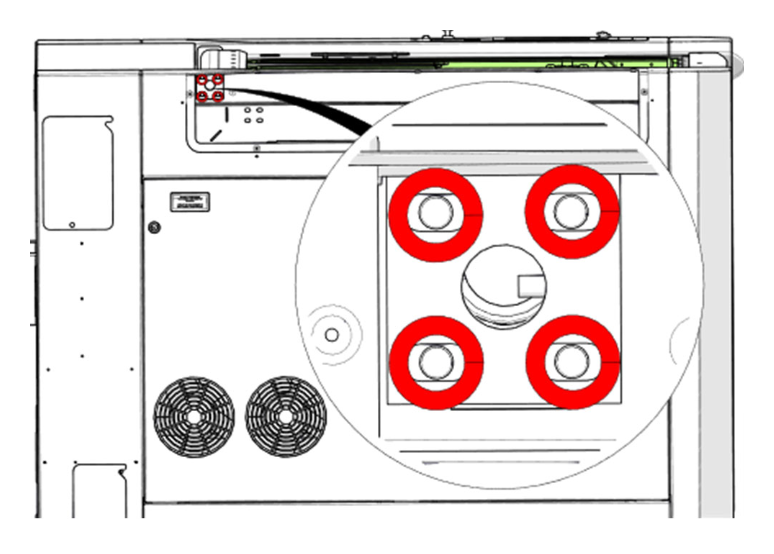
Remove the Left-Hand Hinge
Using a 3/8″ wrench, remove the four nuts and washers that secure the left-hand door hinge to the chassis, then remove the hinge from the machine.
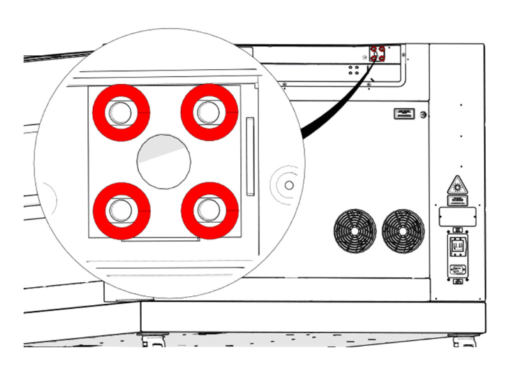
Remove the Right-Hand Hinge
On the right-hand side, use a 3/8″ nut driver to remove the four nuts and washers securing the hinge to the chassis, then remove the right-hand hinge from the machine.
Remove the Top Door
With an assistant, lift the top door off the machine.
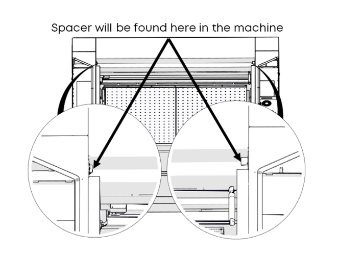
Collect the Door Spacers
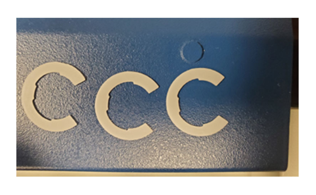
At the rear corners of the machine where the door meets the chassis, collect the door spacers. They set the position of the top door in the machine.
Important: Keep the spacers from each side separate. They must go back on the same side they came from. Spacers may be black or white; both are the same.
Top Door Installation
Position the New Door
Feed the ground wire through the right-hand hinge and position the top door on the machine chassis.
Install the Left-Hand Spacers and Hinge
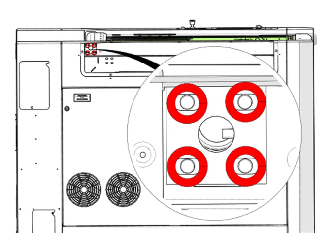
Install the left-hand door spacers and the left-hand door hinge at the same time. Fitting them together makes it easier to keep the spacers in place.
Secure the Left-Hand Hinge
Install the four 3/8″ nuts and washers that secure the left-hand door hinge to the chassis.
Install the Right-Hand Spacers and Hinge
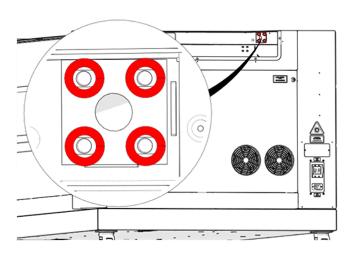
Install the right-hand door spacers and the right-hand door hinge at the same time, then secure the hinge with the four 3/8″ nuts and washers.
Reconnect the Ground Wire
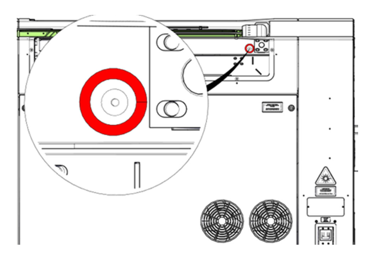
Install the ground wire onto the ground stud.
Install the Gas Shocks
Carefully open the door and have an assistant support it while you install the two gas shocks with the barrel of each shock facing up, as described in the Top Door Gas Shock Replacement article.
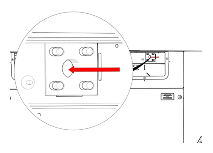
Feed the USB Cables Through the Hinge
Feed the camera USB cables in through the opening in the right-hand door hinge, left-hand camera cable first, then the right-hand camera cable.
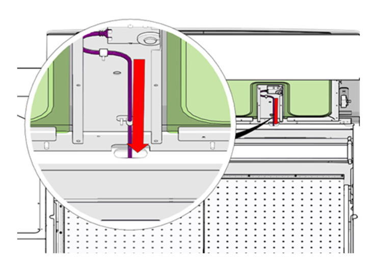
Route the Cables to the Cameras
Continue feeding each cable until it reaches its camera opening in the top door assembly.
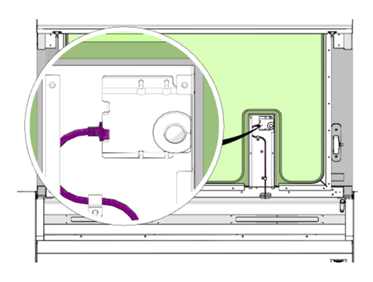
Connect the Camera USB Cables
Connect each USB cable to its camera.
Replace the Camera Covers
Reinstall both camera covers and their screws.
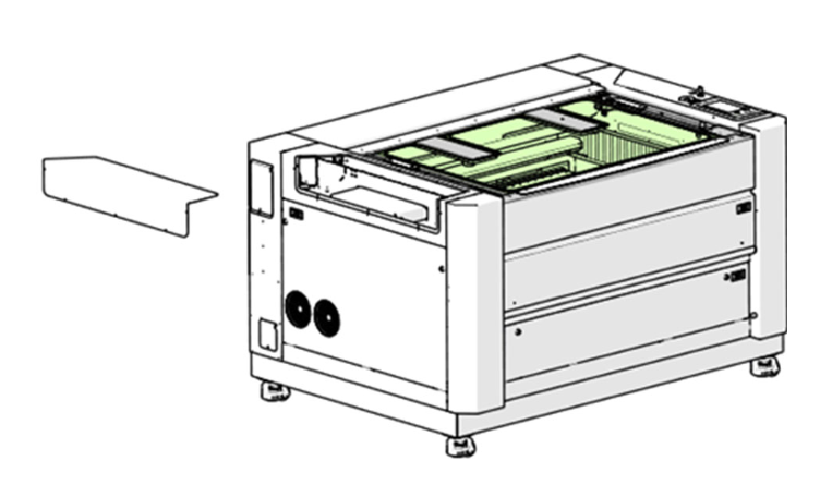
Replace the Left-Hand Bezel
Replace the left-hand blue bezel.
Replace the Right-Hand Bezel
Replace the right-hand blue bezel.
Replace the Control Assembly
Reinstall the control assembly.
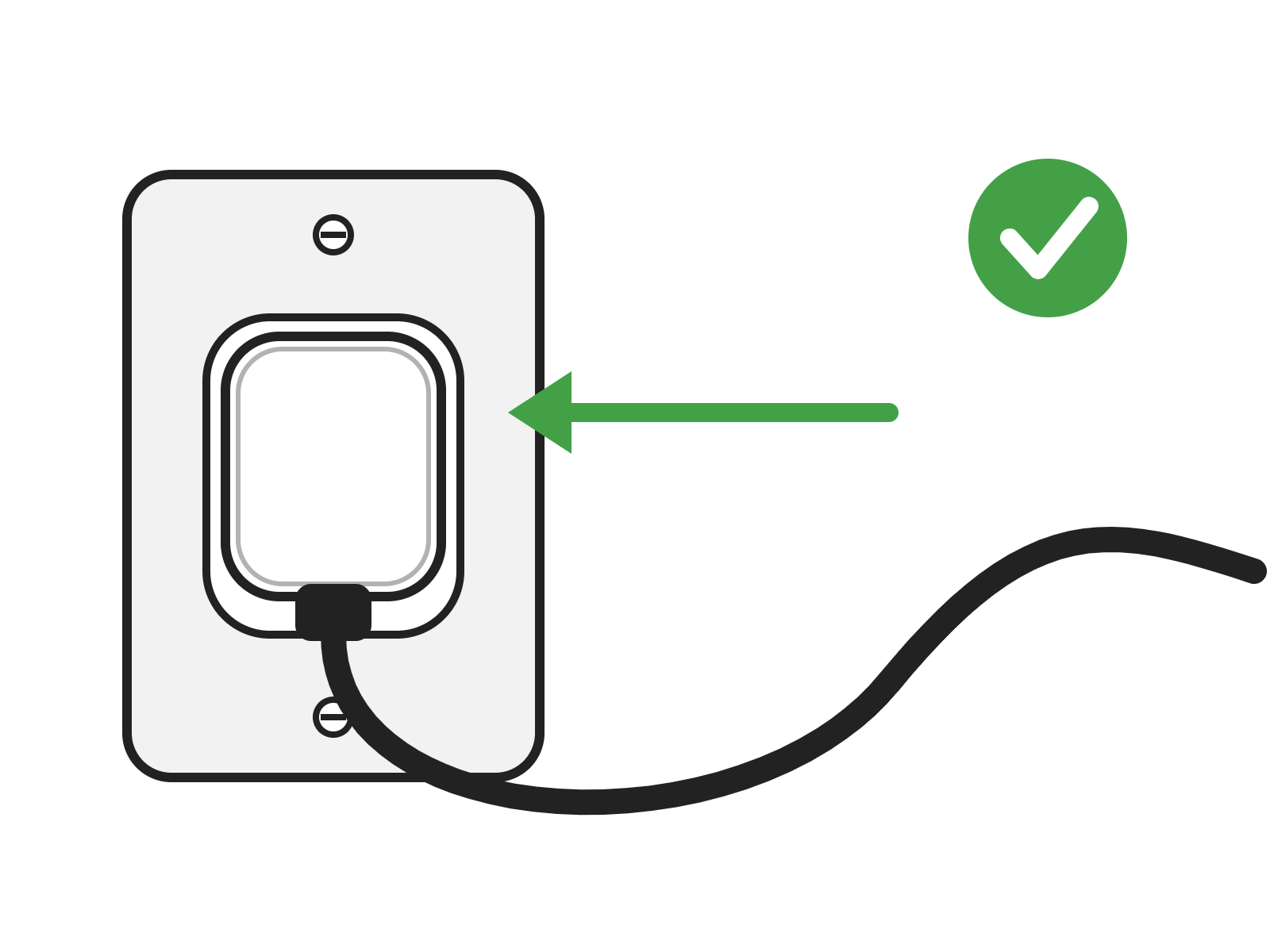
Power On
Reconnect the engraver to its power source and turn it on.
Check the Door and Interlocks
Carefully open and close the door a couple of times to check that it moves properly. Interlock A and B should be on when the door is closed and off when it is open.
Recalibrate the Cameras
After installing the replacement door, recalibrate the cameras. Follow the Camera Calibration article to complete this.