
This guide provides step-by-step technical instructions for replacing the air assist solenoid assembly on your Ascent laser system.
Safety First: Ensure the laser system is completely powered off and the main power cord is unplugged from the wall outlet before touching or disconnecting any internal electronics. Do not touch any exposed power supply components.
Removal Procedure
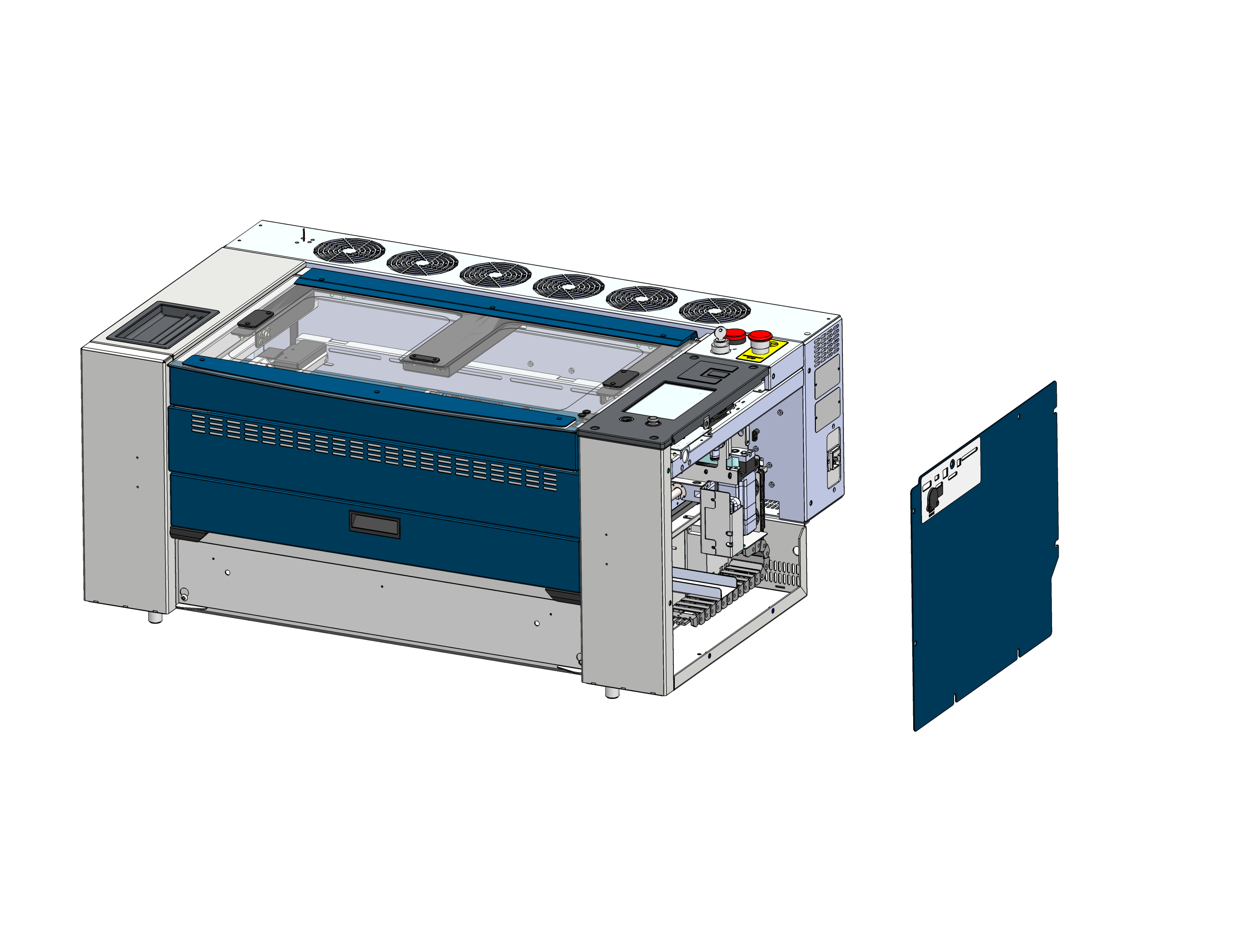
Remove Panel
Locate and remove the right side panel of the laser chassis.
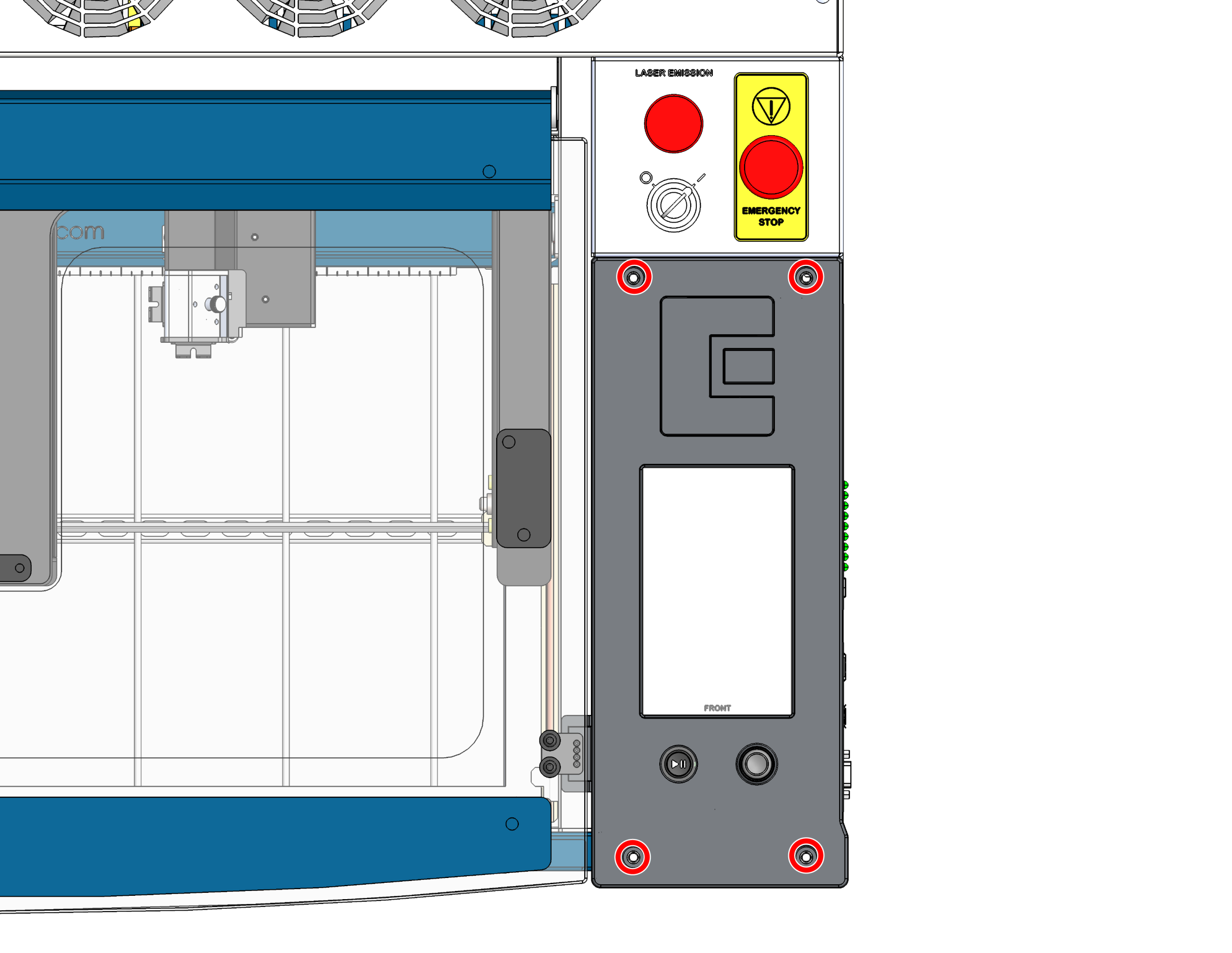
Remove Control Board Screws
Remove the 4 screws securing the control board to the chassis.
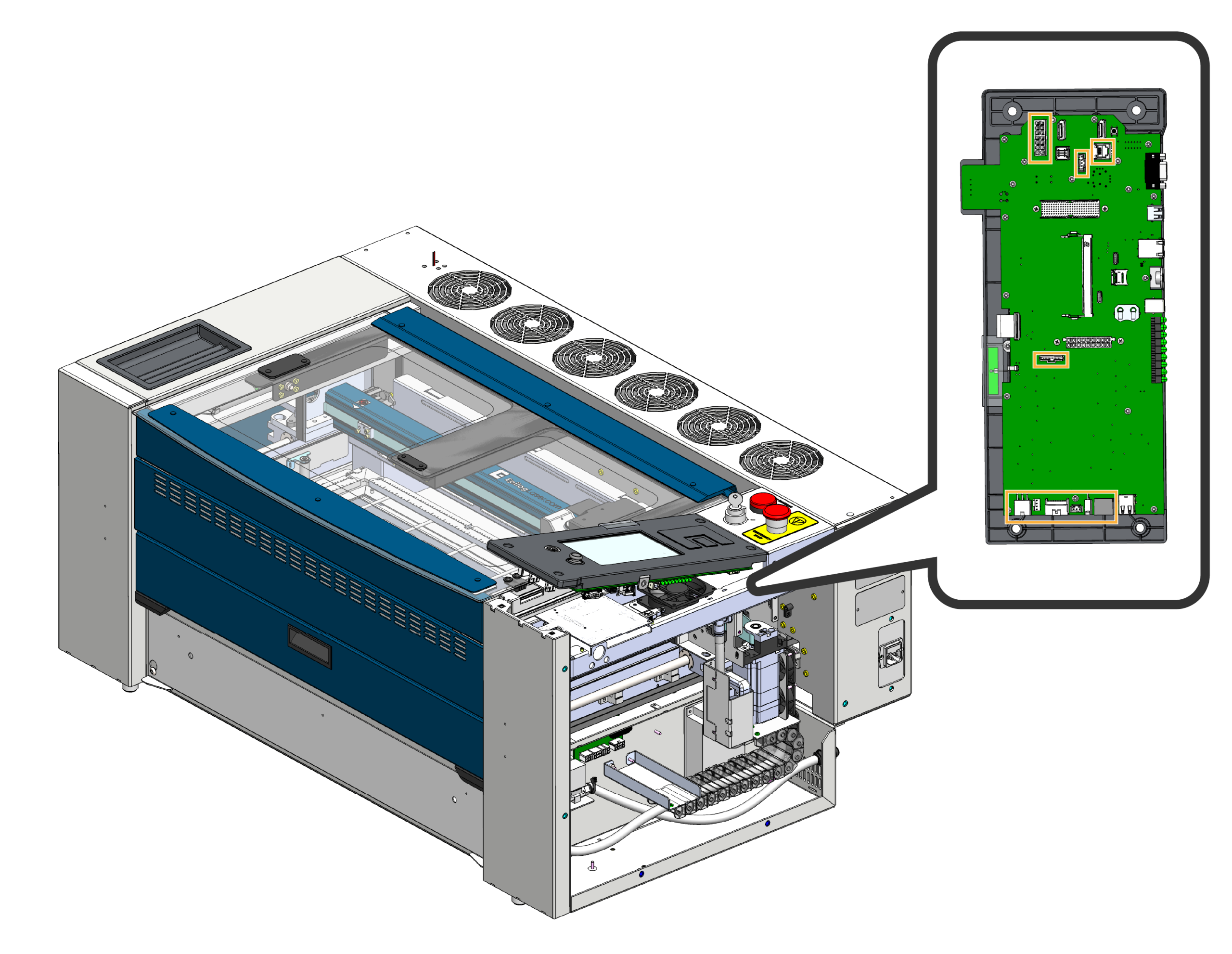
Disconnect Harnessing
Carefully tilt the front of the control board up and disconnect the wiring harnesses plugged into the control board.
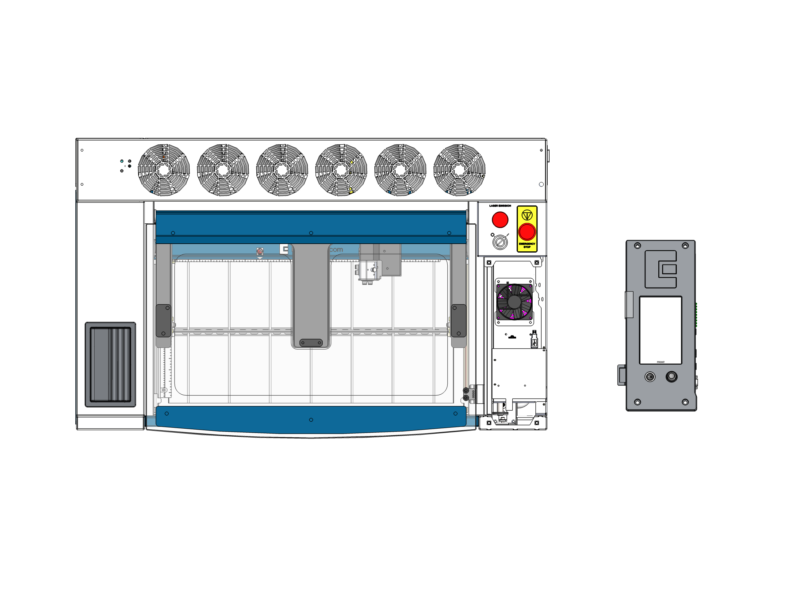
Remove Control Board
Unseat and fully remove the control board from the machine.
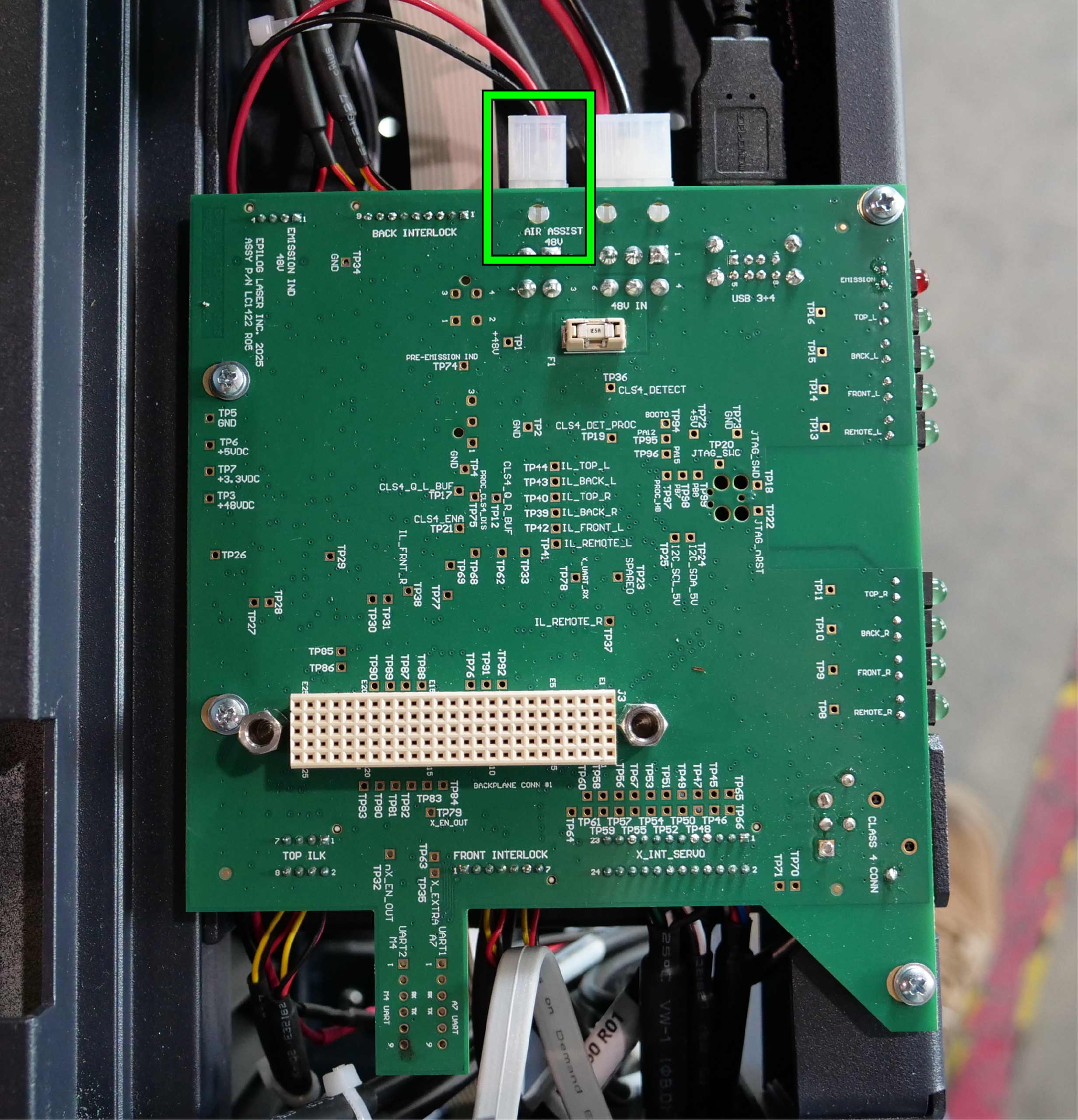
Disconnect Solenoid
Disconnect the air assist solenoid from the backplane. It is labeled “Air Assist Solenoid” on the backplane.
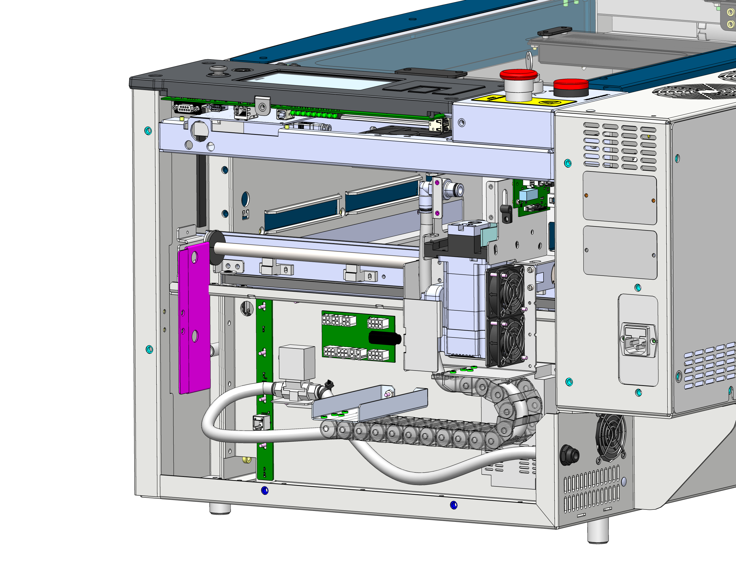
Remove Cable Cover Panel
Locate and remove the internal cable cover panel to reveal the chassis wire harnessing bundles.
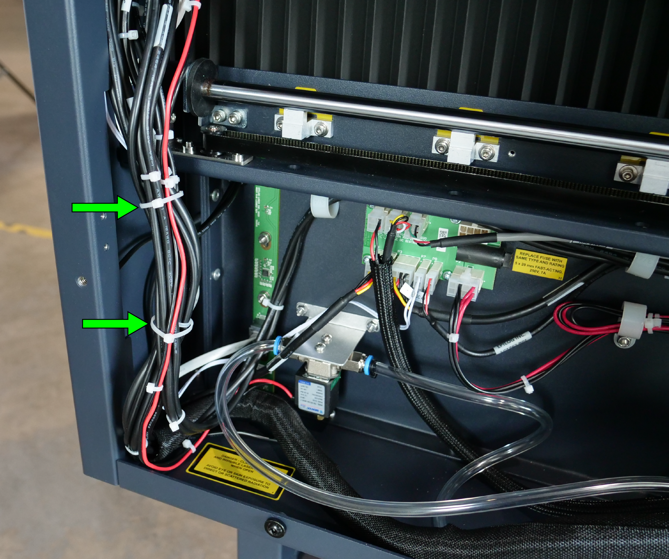
Cut Zip Ties
Carefully cut the zip ties on the harnessing bundle, ensuring you do not nick any of the surrounding wires.
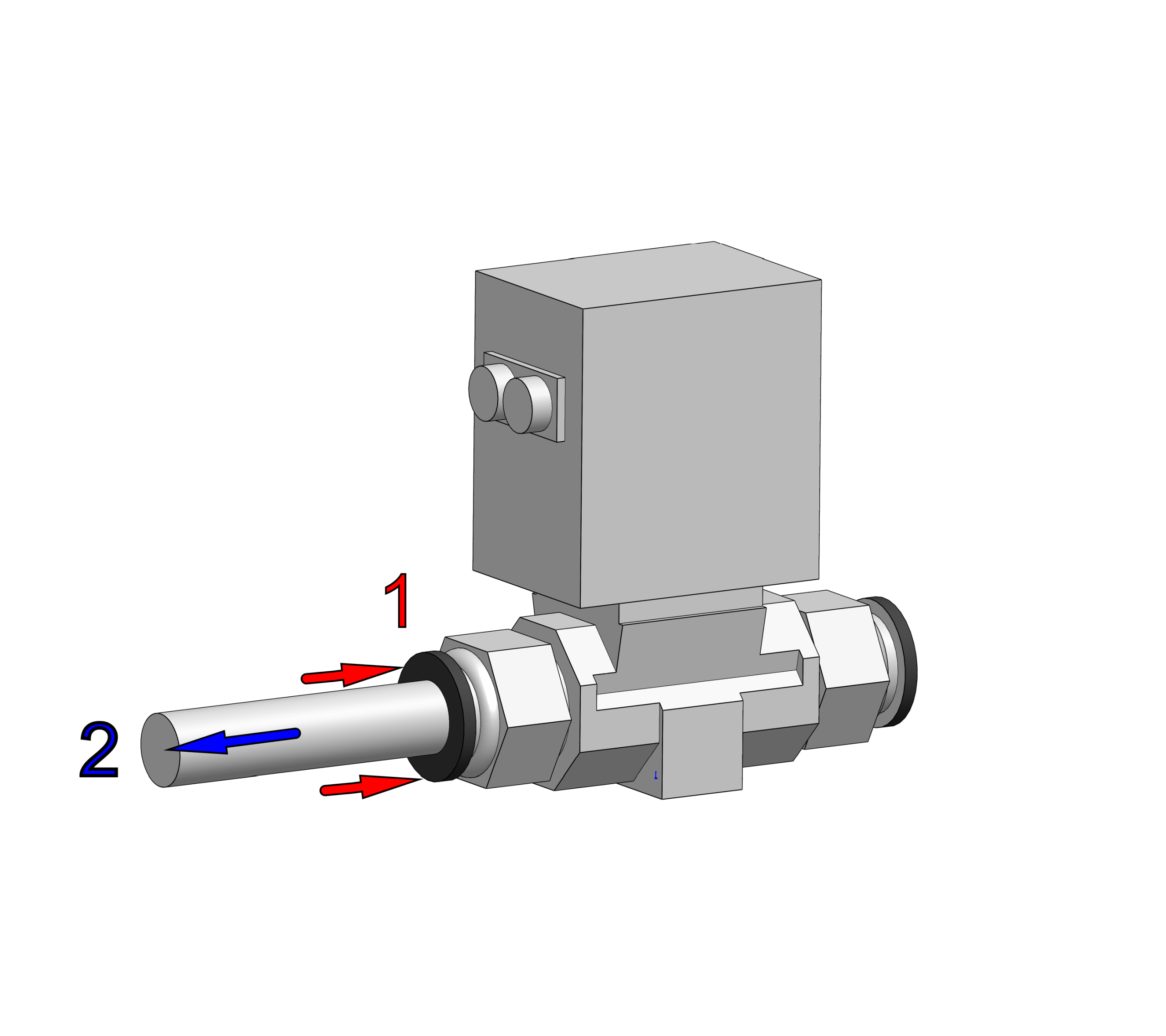
Disconnect Tubing
Press the collar and pull the tubing to disconnect.
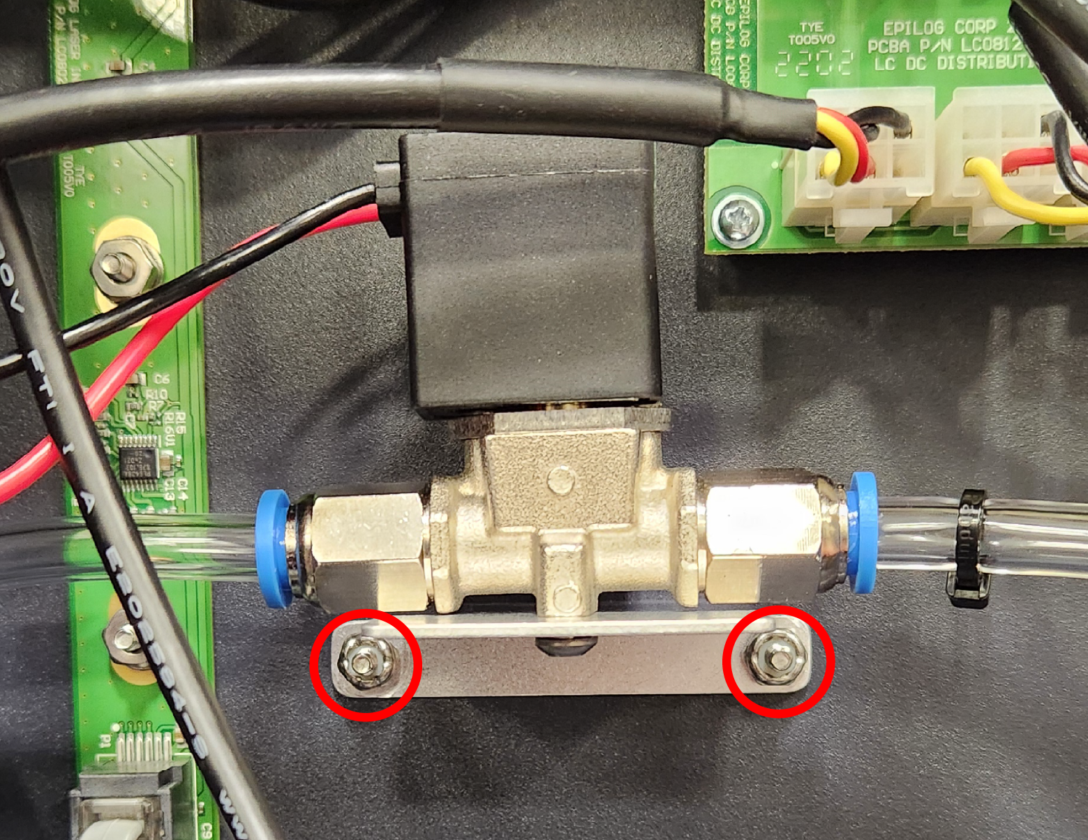
Remove Solenoid
Remove the nuts securing the solenoid bracket and lift the damaged solenoid assembly out of the chassis.
Installation Procedure
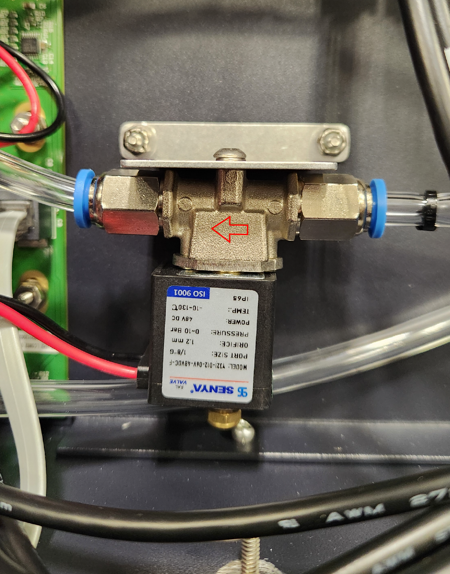
Install Replacement Assembly
Position the replacement solenoid assembly onto the chassis mounting studs and firmly tighten the securing nuts.
Note:
The replacement solenoid should be oriented with the bracket on top of the solenoid. The original solenoid may have had a different orientation. Make sure that the imprinted arrow on the solenoid is facing the front of the machine.
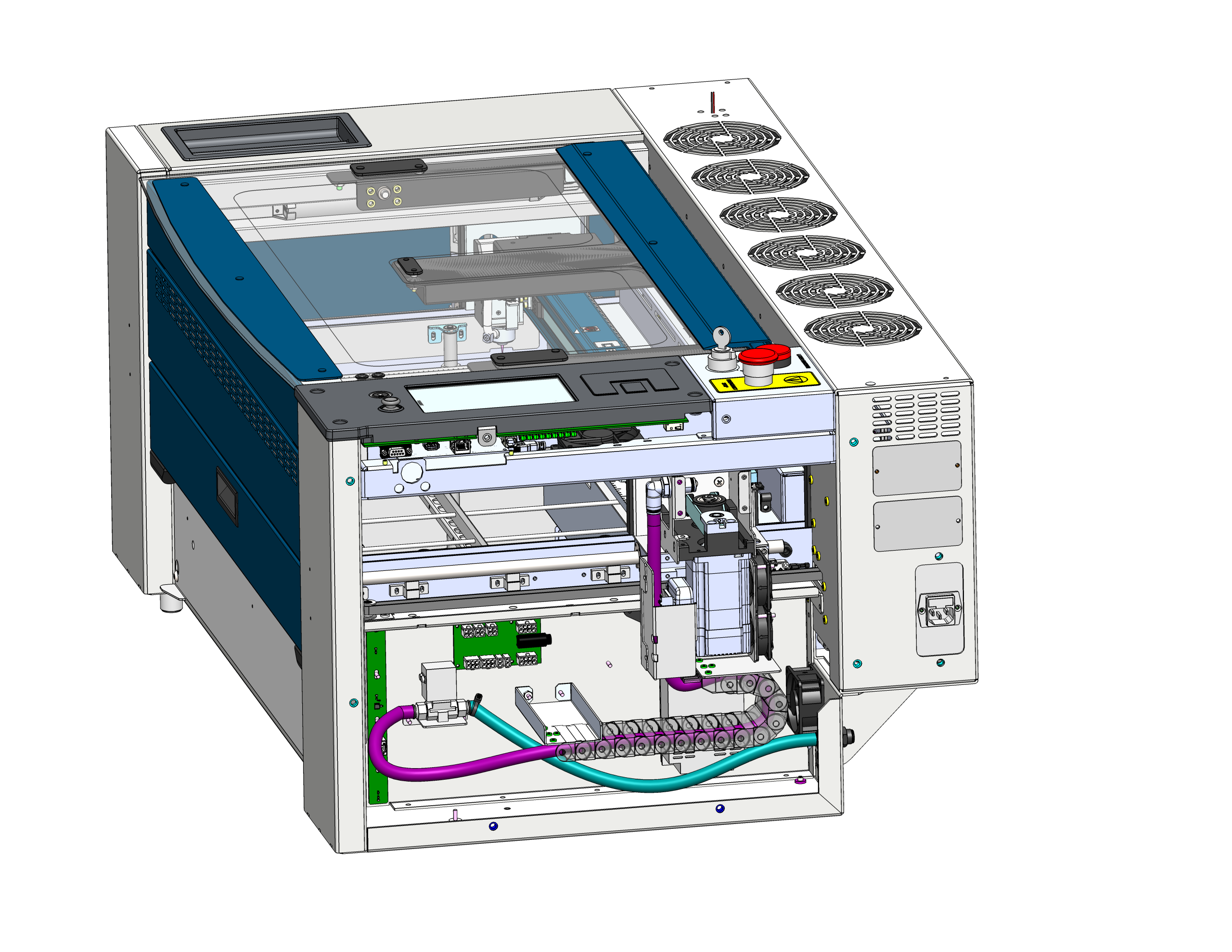
Attach Tubing
Attach the tubing to the solenoid. If using a standard air assist pump the tubing with the zip tie should be attached to the right-side of the solenoid. For more details on how to attach the tubing, please refer to the “Default to Shop Air Conversion” document linked on the right.
Reconnect Solenoid
Route the new wiring harness and plug the air assist solenoid connector securely back into the backplane.
Reconnect Harnessing
Carefully bring the control board close and reconnect the wiring harnesses to the board.
Seat Control Board
Center the control board directly above the screw holes. Press down evenly and firmly to ensure the board makes a solid connection to the backplane.
Secure Control Board
Reinstall and tighten the 4 screws to secure the fully seated control board to the chassis.
Secure Harnessing
Now that everything is connected, apply fresh zip ties to cleanly secure the solenoid wiring alongside the main bundle.
Reinstall Cable Cover
Reattach and secure the internal cable cover panel over the wiring bundles.
Replace Side Panel
Reinstall and secure the right side panel of the machine.
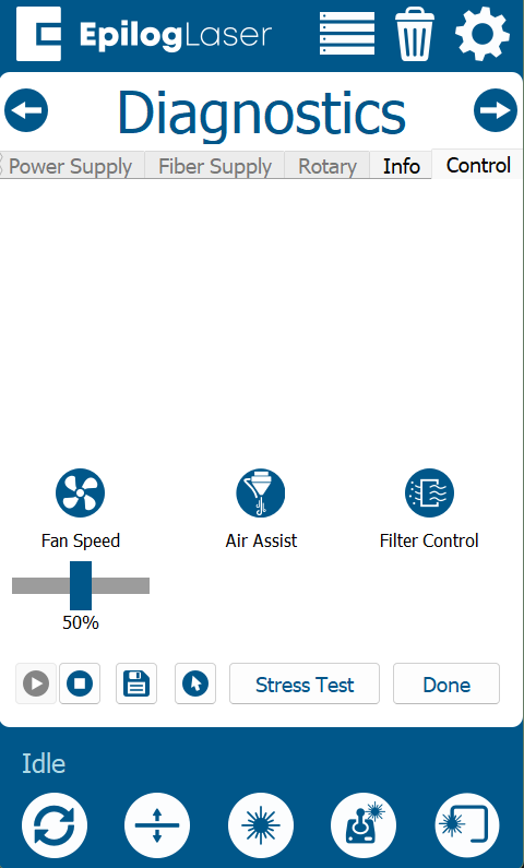
Final Verification Test
Plug the machine back into the wall outlet and power it on. Navigate to the Diagnostics environment to perform a digital test cycle:
Gear Icon Long-press “Settings” Diagnostics “Control” Tab Click Air Assist.
Manually toggle the control and verify that pressurized air completely opens and closes at the laser carriage nose cone.