Important: All focus calibration procedures must be completed before performing a camera calibration to ensure accurate results.
Click the tabs below to switch between machine types. Each tab shows the camera calibration procedure specific to that machine.
-
The IRIS camera calibration ensures accurate artwork placement and reliable print-to-cut operations. It should only be completed when specific issues occur or after hardware changes.
Perform if you observe:
- Black camera feed or semi-circle overlay.
- Feed rotated 90–180 degrees.
- Artwork alignment offset.
Perform after changing:
- Overhead or carriage camera.
- Laser focus calibration.
- Machine home position.
-
Overhead Camera Calibration (Fusion Edge)
3 Calibrate Cameras
Choose the path that matches your current firmware version:
1.1.2.8 or olderSelect Calibrate Cameras.
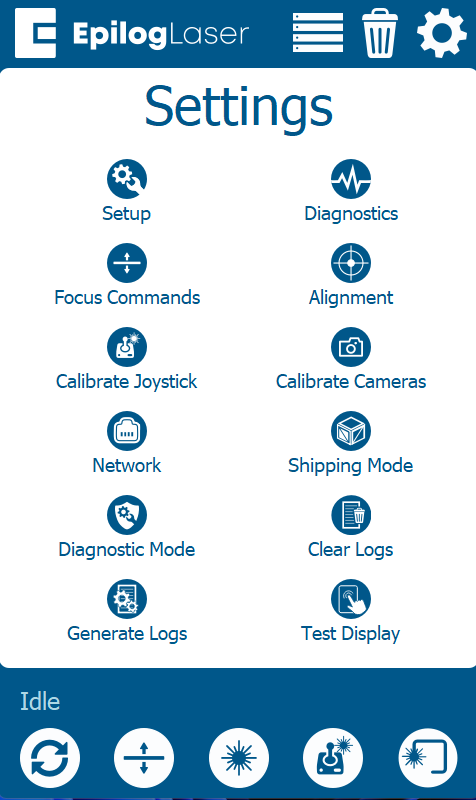 1.1.3.2 or newer
Select Calibration → Calibrate Cameras.
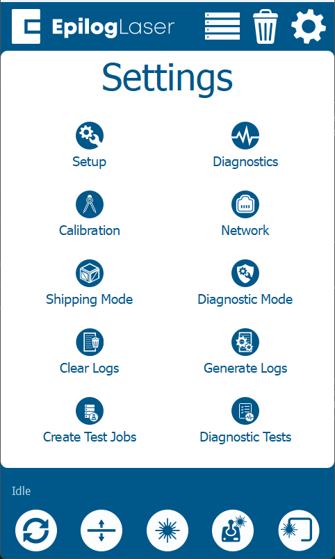
4 Run Calibration
- Place Anodized Aluminum: Use 24×12″ sheets (Edge 12: 1, Edge 24: 2, Edge 36: 3).
- Start Process: Close the door and press OK.
- Wait: Allow 15–30 minutes for analysis.
- Verify: Follow prompts to complete calibration.
-
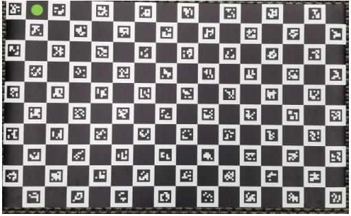
Calibration Mat Required
Note: If the mat is curled, allow it to sit on a flat surface until it is perfectly flat. An unrolled, flat mat is essential for accurate results.
First complete the carriage camera calibration. After finishing, switch to the Overhead tab below.
-
3 Select Calibration Path
Choose the path that matches your current firmware version:
1.1.2.8 or olderTap: Calibrate Cameras
1.1.3.2 or newerTap: Calibration → Calibrate
4 Engrave Pattern
- Place an 8″ × 5″ piece of anodized aluminum in the upper-left corner.
- Close the door and press OK to engrave the pattern.
- Follow prompts to complete calibration.
-
Overhead Calibration Process
- Install Mat: Place calibration mat in the upper-left.
- Positioning: Ensure the green circle is in the corner.
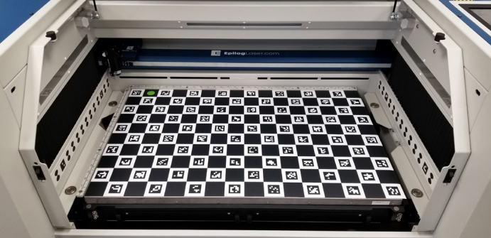
- Run: Close doors and press OK.
- Verify: Follow prompts to complete calibration.
-