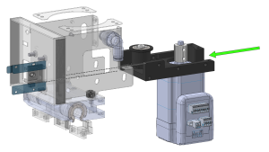
This guide covers replacing the X-axis linear guide (the rail and its bearing block) on the Fusion Ascent 24×12 and 24×24. The lens carriage is unbolted and moved aside, the carriage plate comes off the bearing block at the right-hand end of the X-axis assembly, and the linear guide is unscrewed and lifted out of the front of the X-axis assembly. Read through the whole procedure before you start. Directions such as left-hand and right-hand are given as if you are facing the front of the machine. In the images, orange marks parts to remove, green marks parts to install, blue marks screws to loosen, and yellow arrows show parts to slide or move.
Parts Required
- LC0094 Linear Guide
Tools Required
- 5/32″ Allen Wrench
- 3/32″ Allen Wrench
- Epilog Belt Tensioning Tool
Safety First: Turn off the engraver and unplug it from power before removing any panels. Wear safety glasses throughout this procedure.
Linear Guide Removal
Turn Off Engraver
Turn off the engraver.
Disconnect from Power
Unplug the engraver from its power source.
Open the Top Door
Open the top door of the engraver.
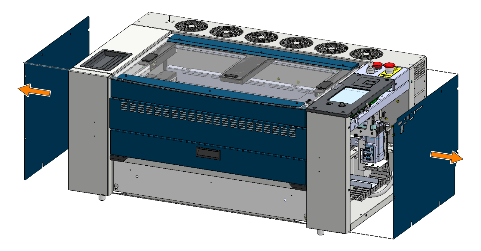
Remove the Side Panels
Remove the left-hand and right-hand side panels.
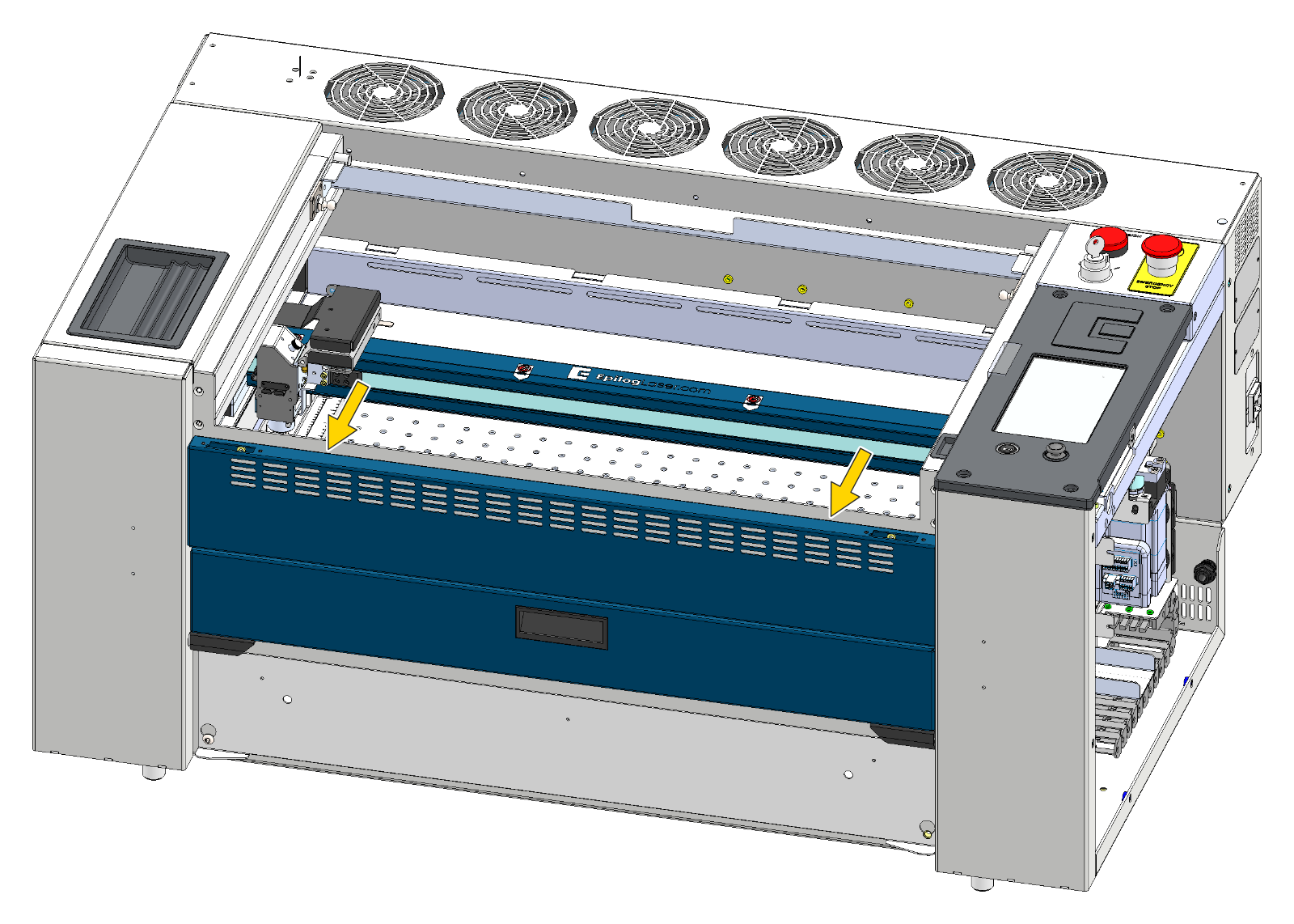
Move the X-Axis to the Front
With the top door open, pull the X-axis assembly by hand toward the front of the machine.
Center the Lens Carriage
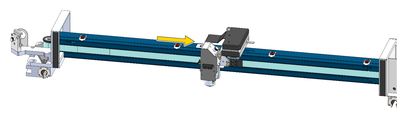
Slide the lens carriage by hand to the center of the X-axis assembly.
Release the Belt Tension
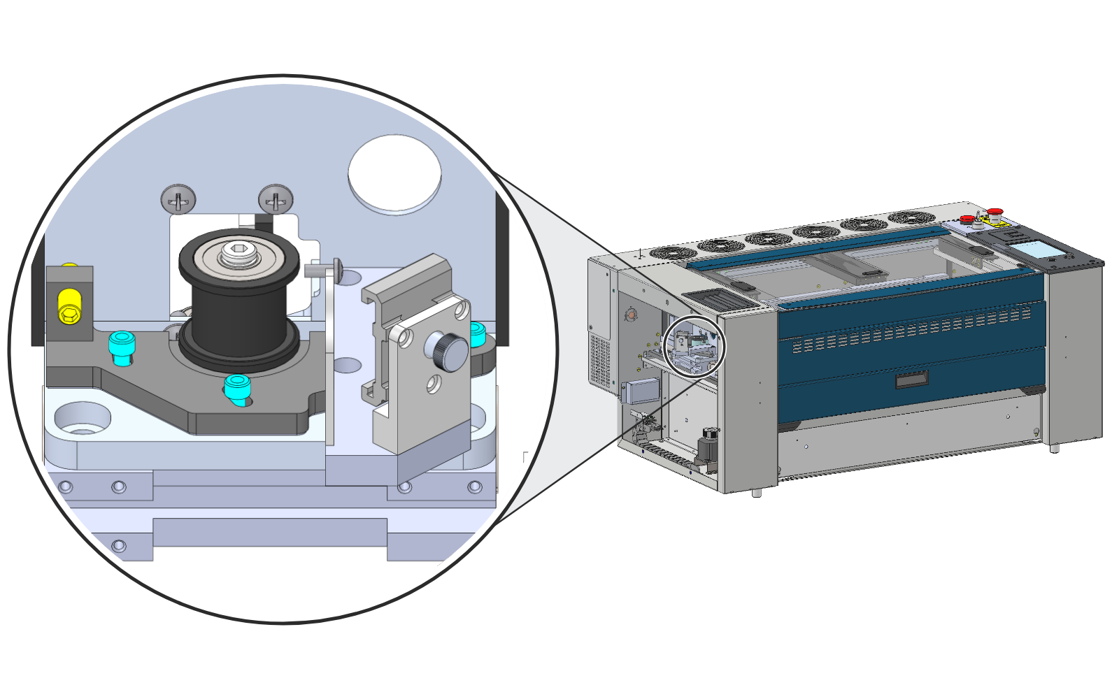
At the left-hand side of the machine, loosen the three Allen screws (blue), then loosen the tensioner screw (yellow) to take the tension off the X-axis belt.
Remove the Air Assist Cone
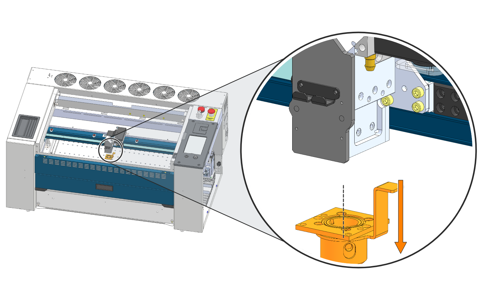
Remove the air assist cone (orange) from the bottom of the lens carriage and set it aside.
Remove the Lens Carriage Screws
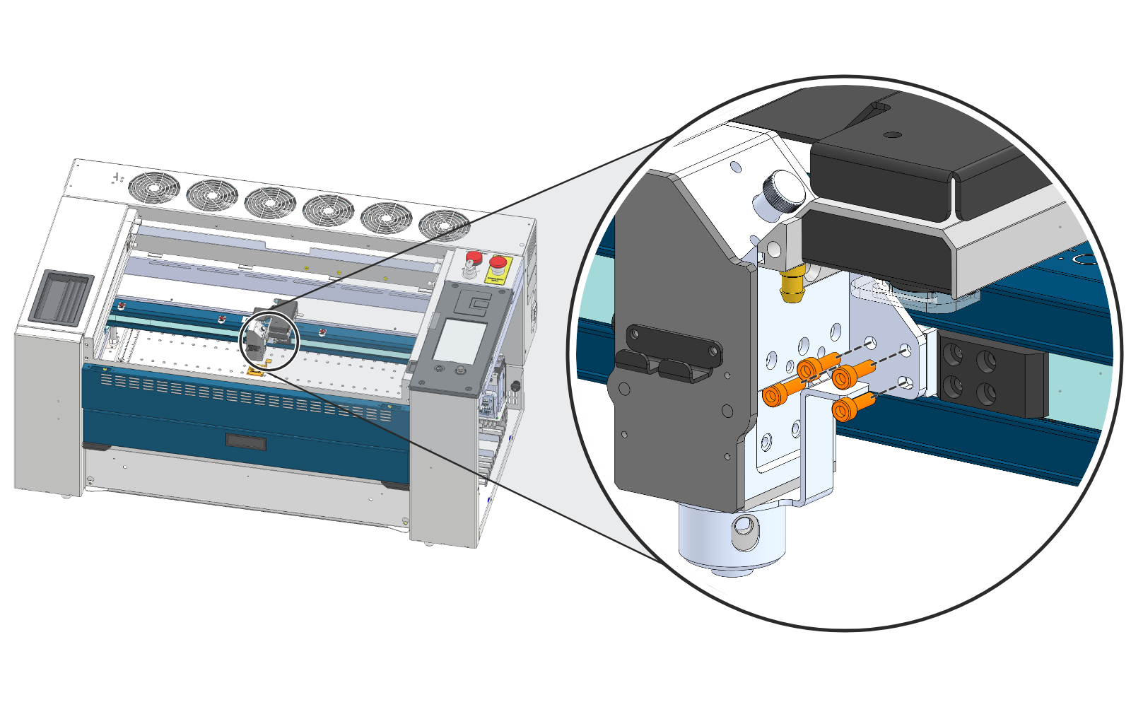
Remove the four screws (orange) that secure the lens carriage to the carriage plate.
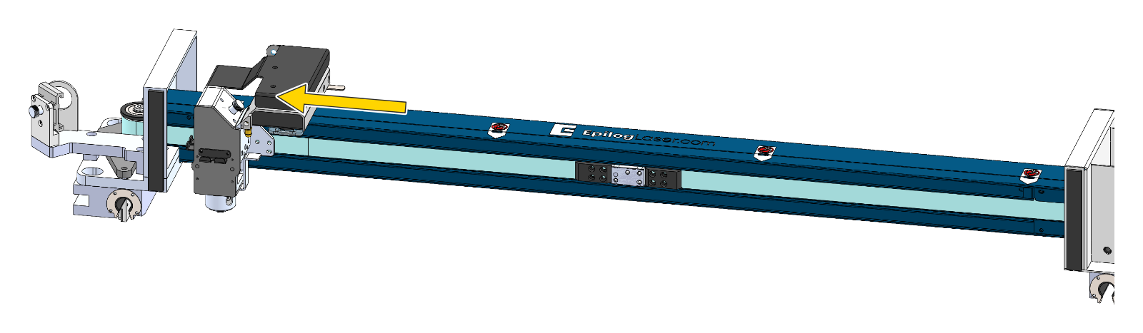
Slide the Lens Carriage to the Left
Slide the lens carriage to the left-hand side, away from the carriage plate, and leave it out of the way. The carriage plate and belt clamps stay at the center. The lens carriage is not shown in the following images.
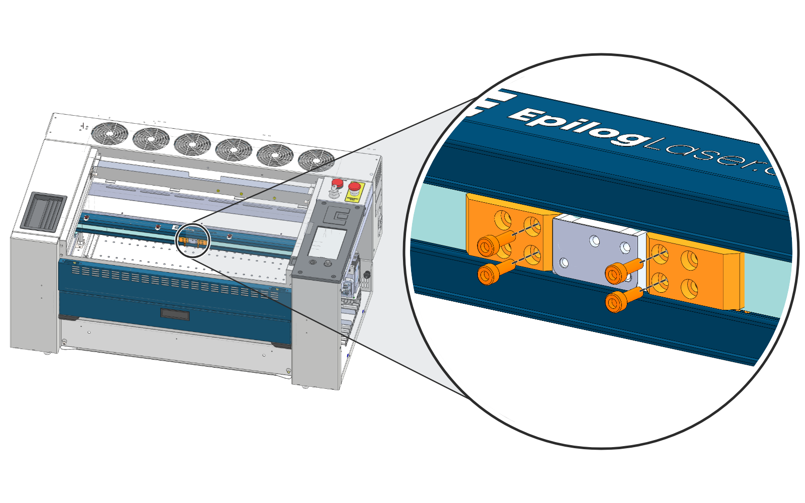
Remove the Belt Clamp Screws
Remove the four screws (orange), two in each belt clamp, that secure the belt clamps to the carriage plate.
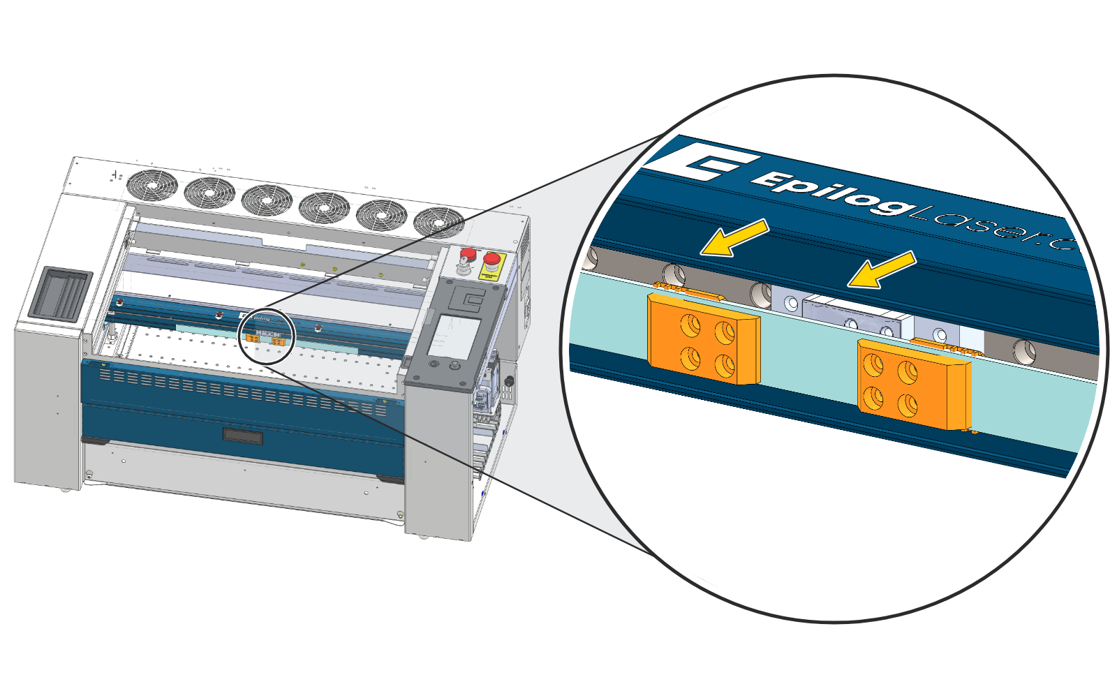
Pull the Belt Out of the Groove
Using the belt clamps as handles, pull the X-axis belt forward and out of its groove in the front of the X-axis assembly. This exposes the linear guide. Let the belt and clamps hang in front of the X-axis assembly.
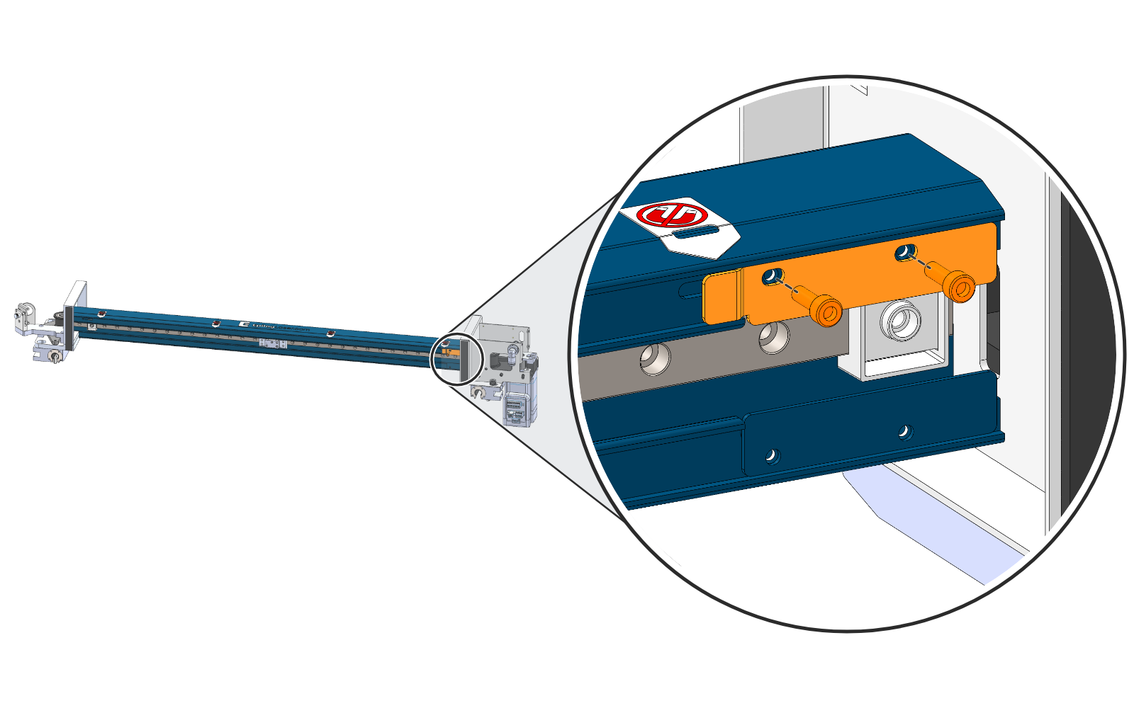
Remove the Encoder Strip Clamp Screws
At the right-hand end of the X-axis assembly, remove the two screws (orange) that secure the upper encoder strip clamp.
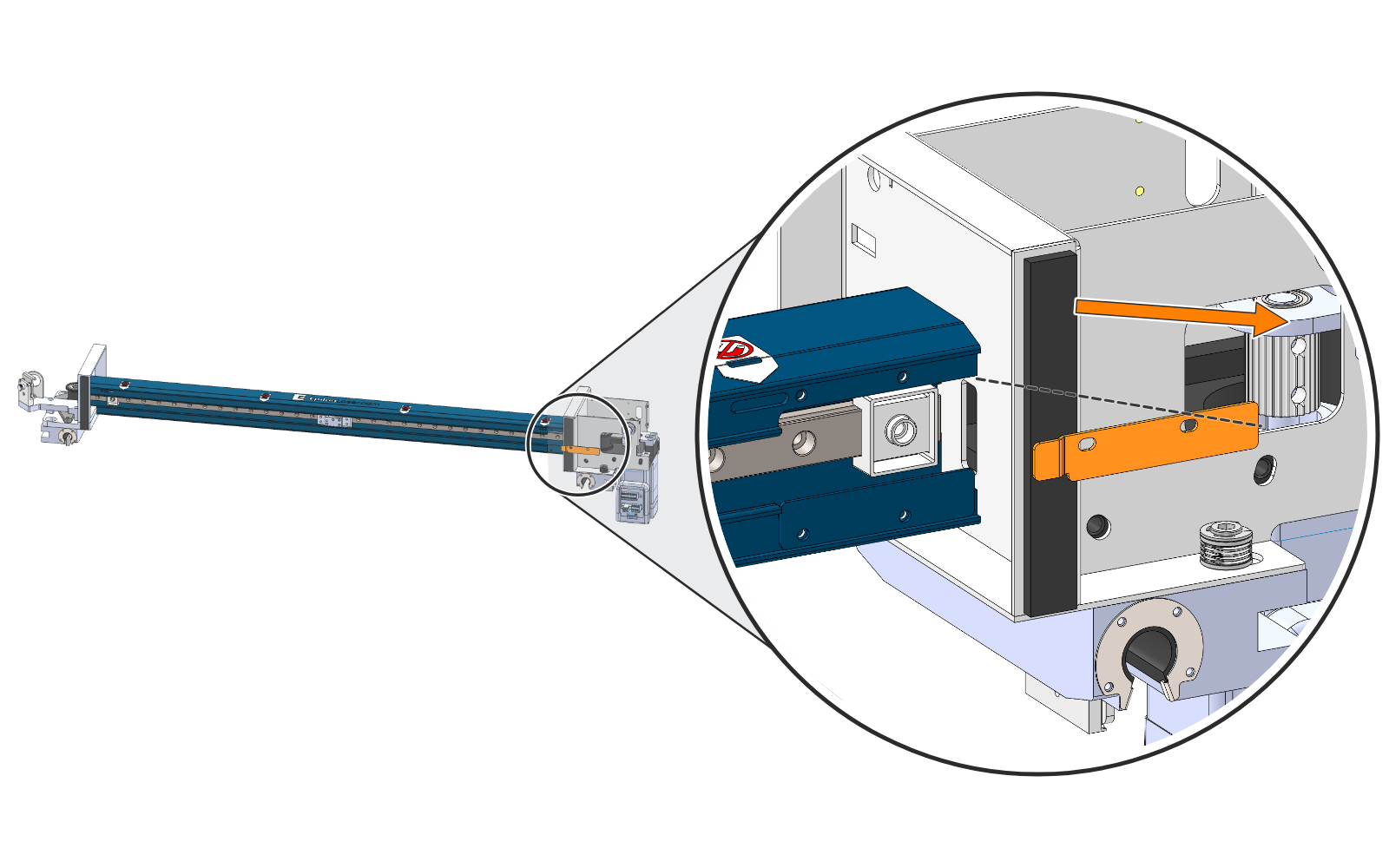
Remove the Encoder Strip Clamp
Slide the encoder strip clamp out toward the right-hand side.
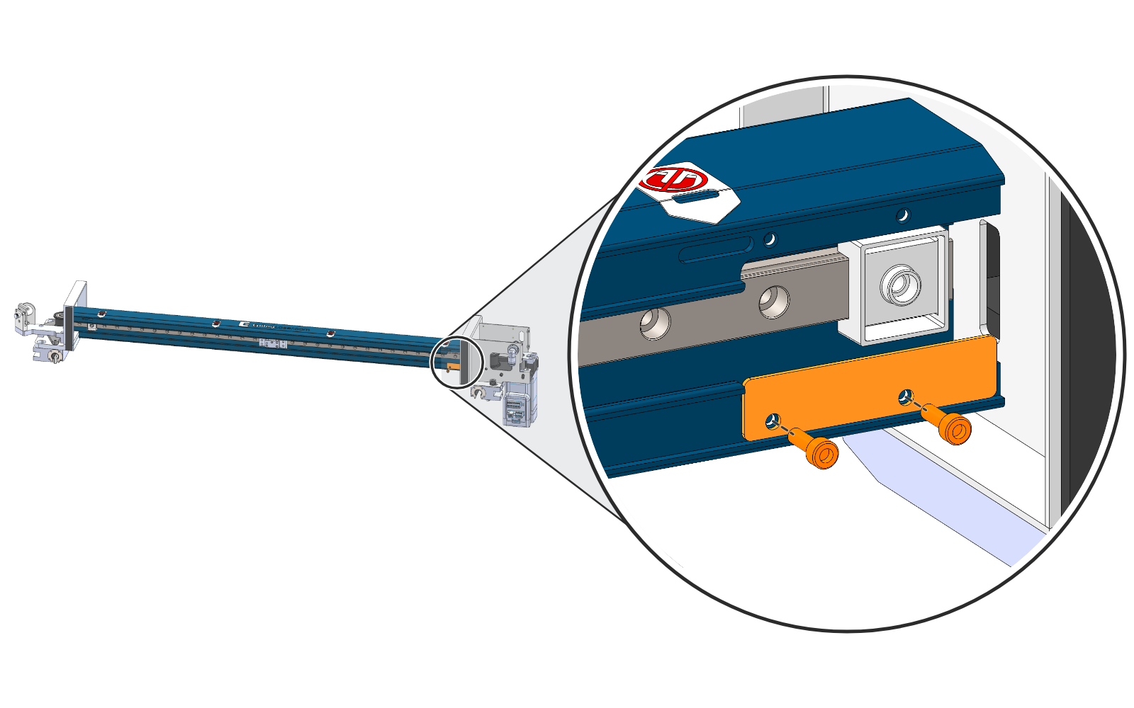
Remove the Lower Shield Screws
Remove the two screws (orange) that secure the lower shield.
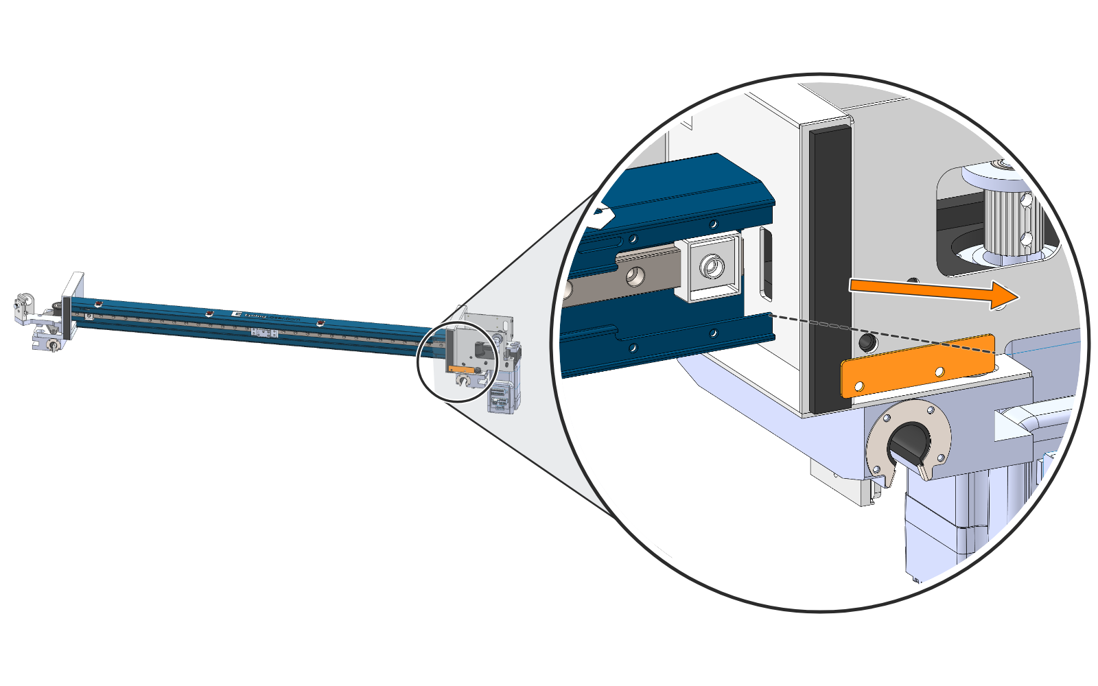
Remove the Lower Shield
Slide the lower shield out toward the right-hand side.
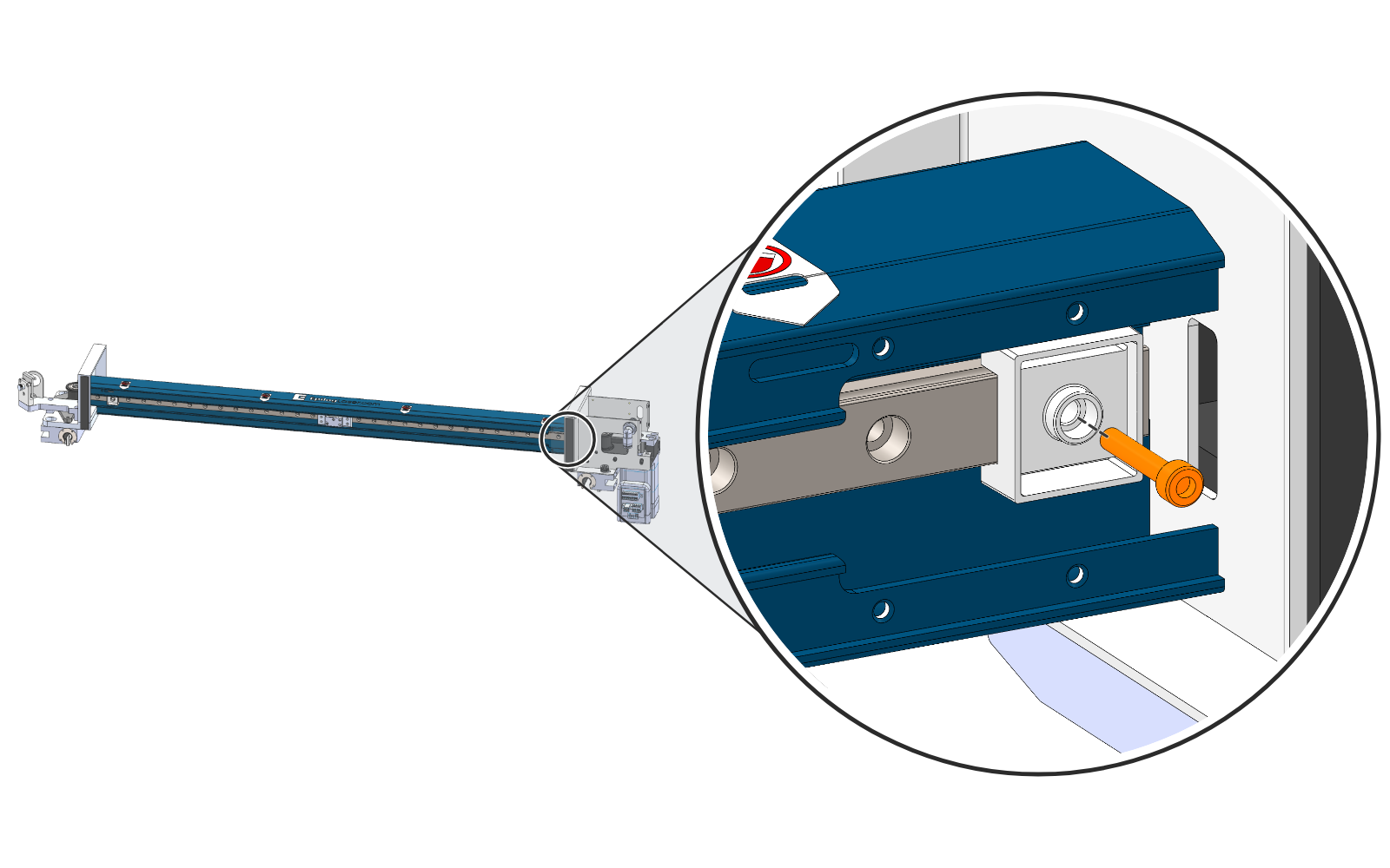
Remove the Right Hard Stop Screw
Remove the screw (orange) that secures the right-hand hard stop.
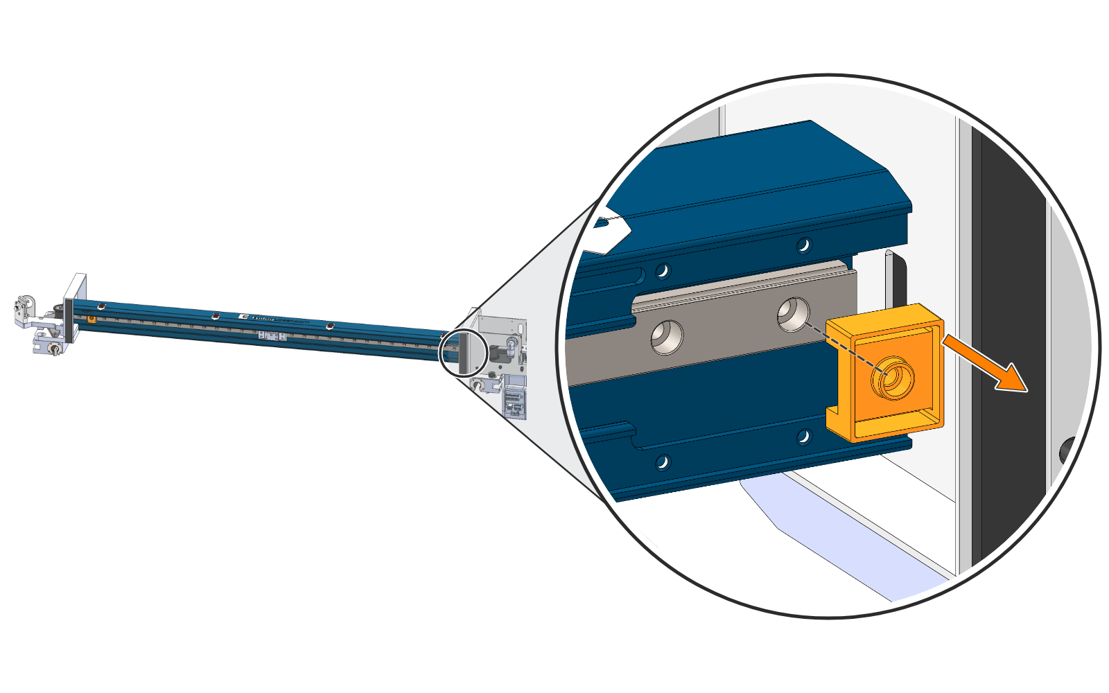
Remove the Right Hard Stop
Remove the right-hand hard stop.
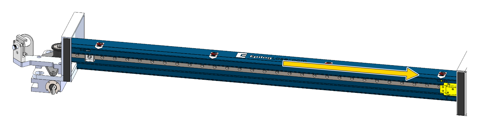
Move the Carriage Plate to the Right
Slide the carriage plate and bearing block to the right-hand end of the X-axis assembly, into the opening left by the encoder strip clamp and lower shield.
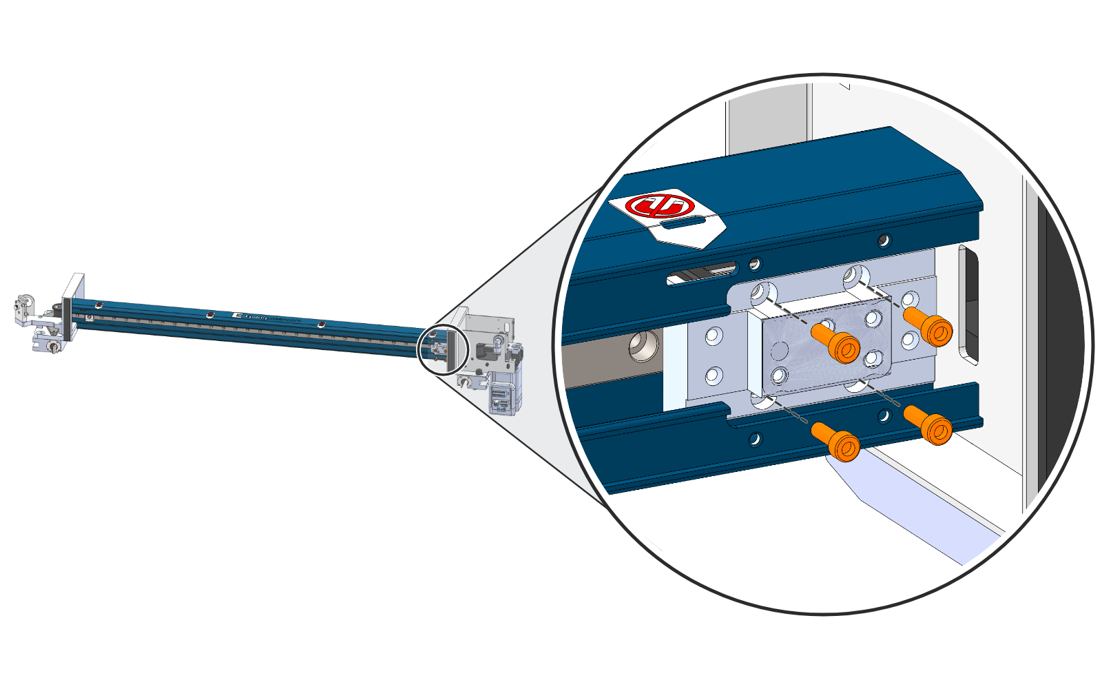
Remove the Carriage Plate Screws
Remove the four screws (orange) that secure the carriage plate to the bearing block.
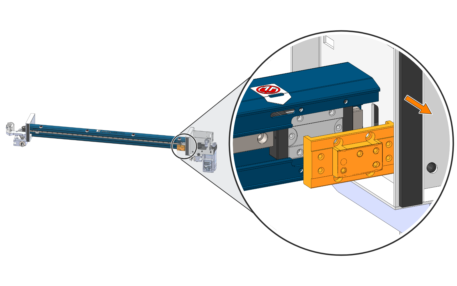
Remove the Carriage Plate
Pull the carriage plate off the bearing block and out through the opening. The bearing block stays on the rail.
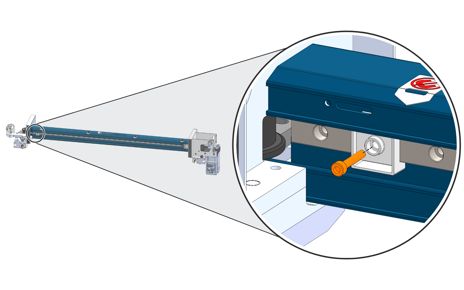
Remove the Left Hard Stop Screw
At the left-hand end of the X-axis assembly, remove the screw (orange) that secures the left-hand hard stop.
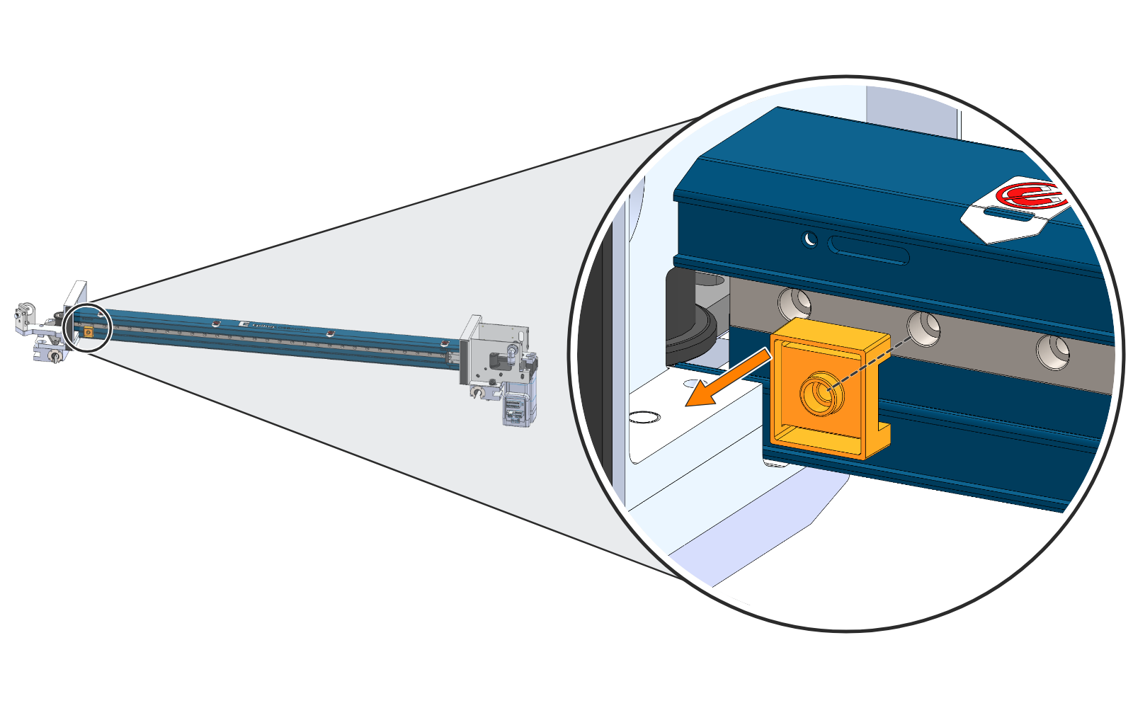
Remove the Left Hard Stop
Remove the left-hand hard stop.
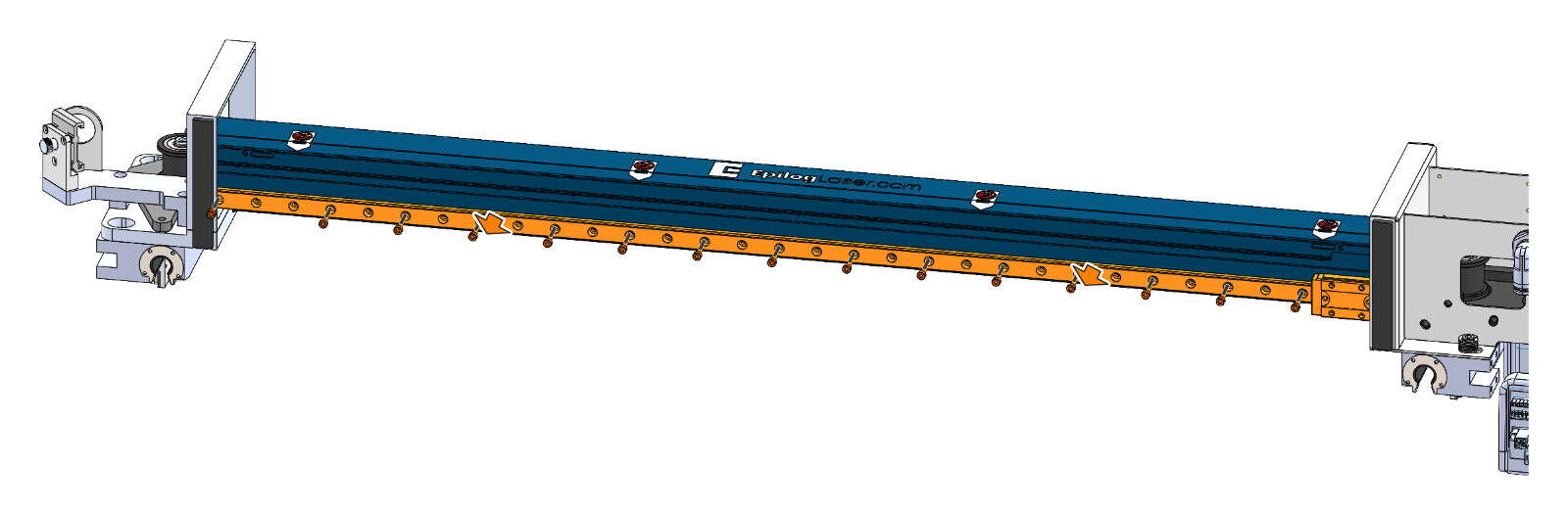
Remove the Linear Guide
Remove the screws (orange) that secure the linear guide rail to the X-axis assembly, then lift the linear guide out of the front of the X-axis assembly.
Linear Guide Installation
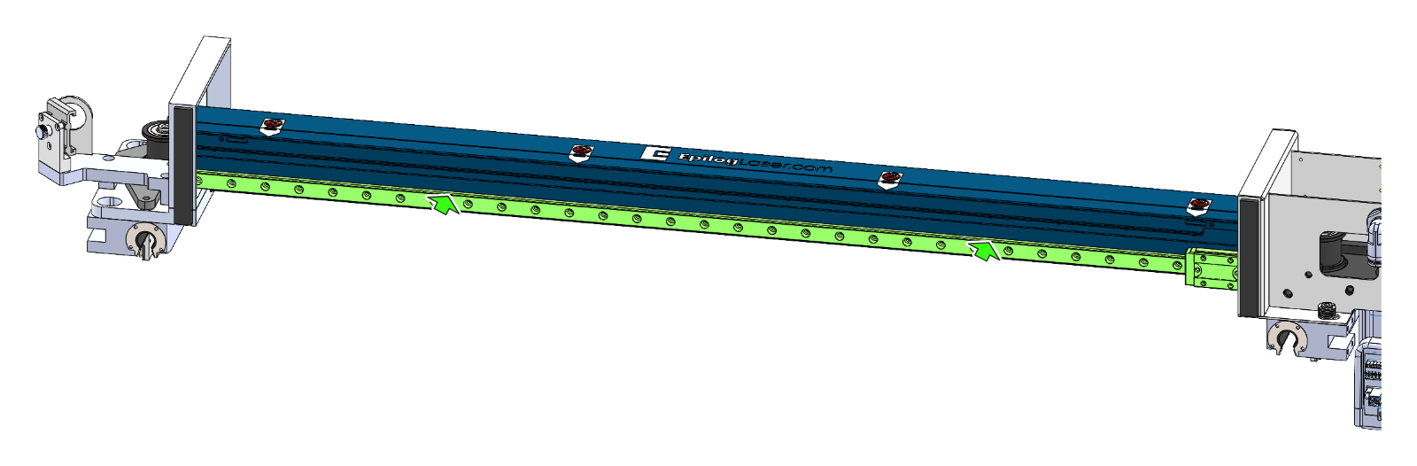
Install the New Linear Guide
Remove the new linear guide from its packaging. Slide the bearing block to the right-hand end of the rail, lined up with the opening at the right-hand end of the X-axis assembly, and set the linear guide into the X-axis assembly.
Caution: Do not let the bearing block slide off the end of the rail. The balls inside the block can fall out.
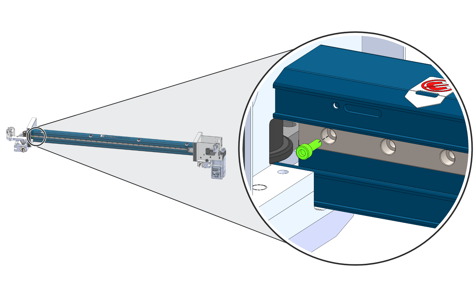
Install the First Screw
At the left-hand end, install the screw (green) in the first hole of the rail.
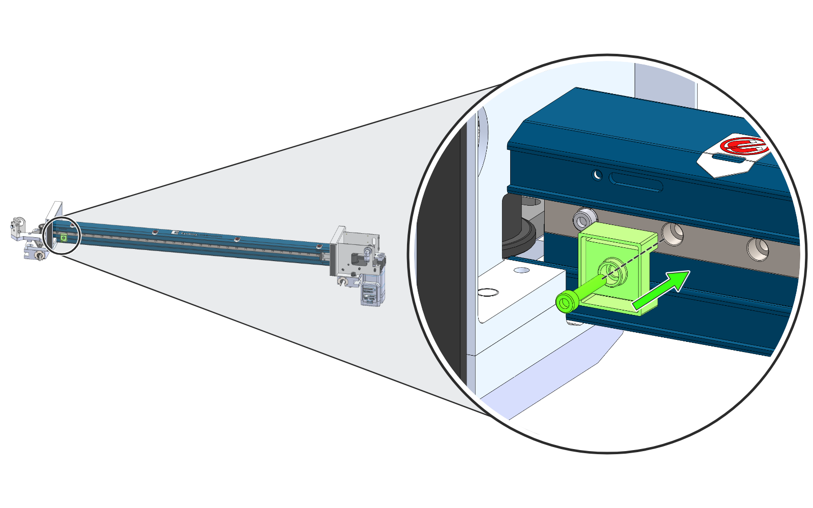
Install the Left Hard Stop
Install the left-hand hard stop over the second hole of the rail, and secure it with its screw (green).
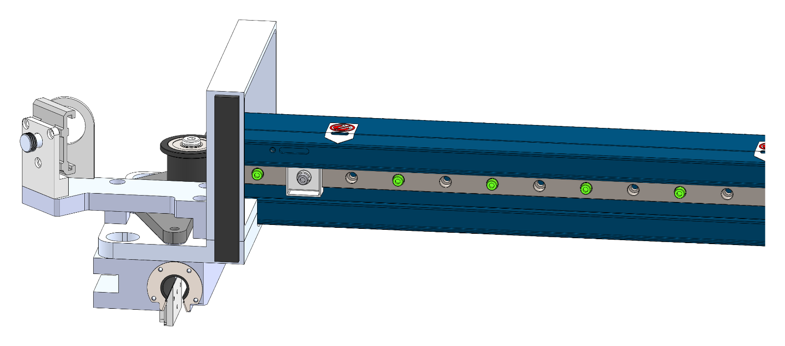
Install the Remaining Rail Screws
Install the remaining screws (green) in an alternating pattern: skip the third hole and install a screw in the fourth, then continue to skip every other hole all the way to the right-hand end.
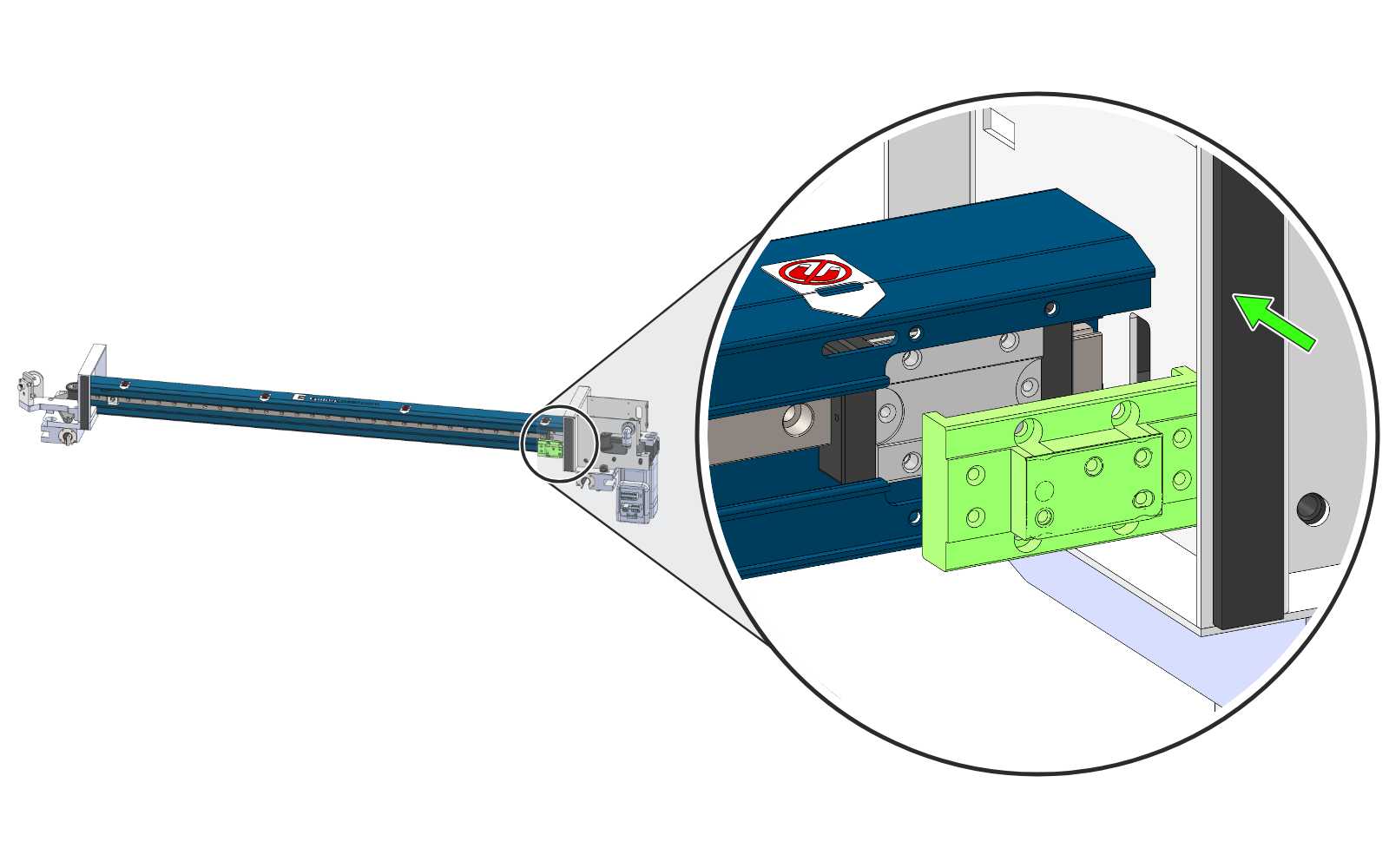
Install the Carriage Plate
At the right-hand end, fit the carriage plate onto the bearing block through the opening.
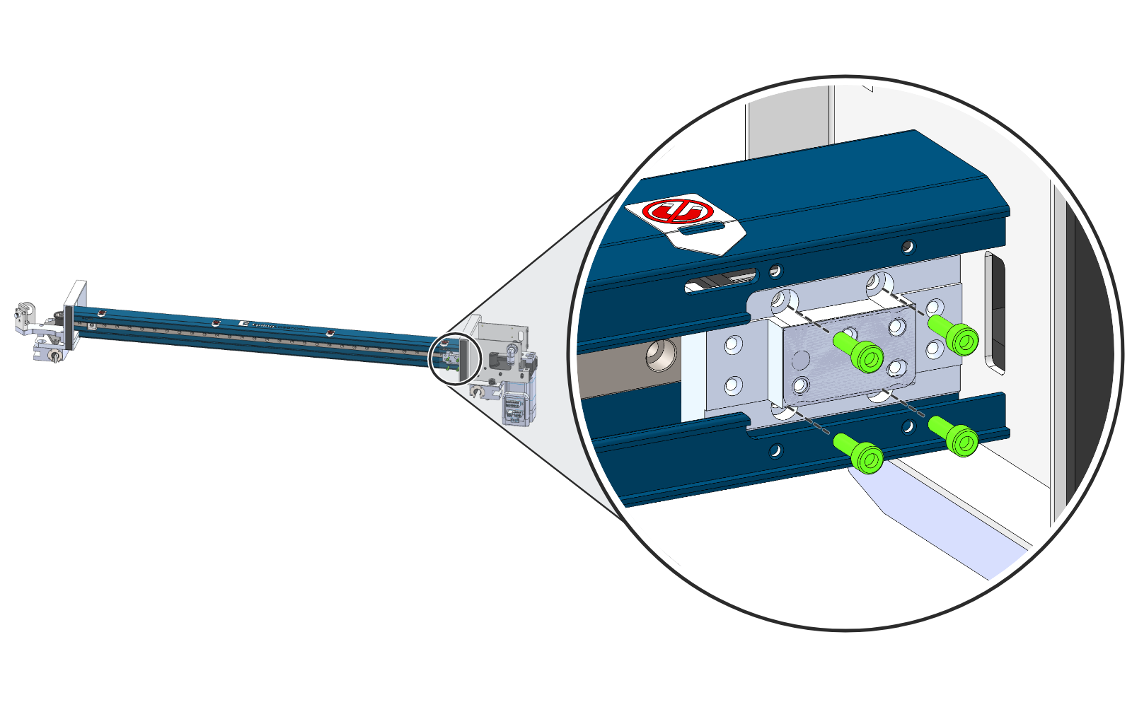
Install the Carriage Plate Screws
Install the four screws (green) that secure the carriage plate to the bearing block.
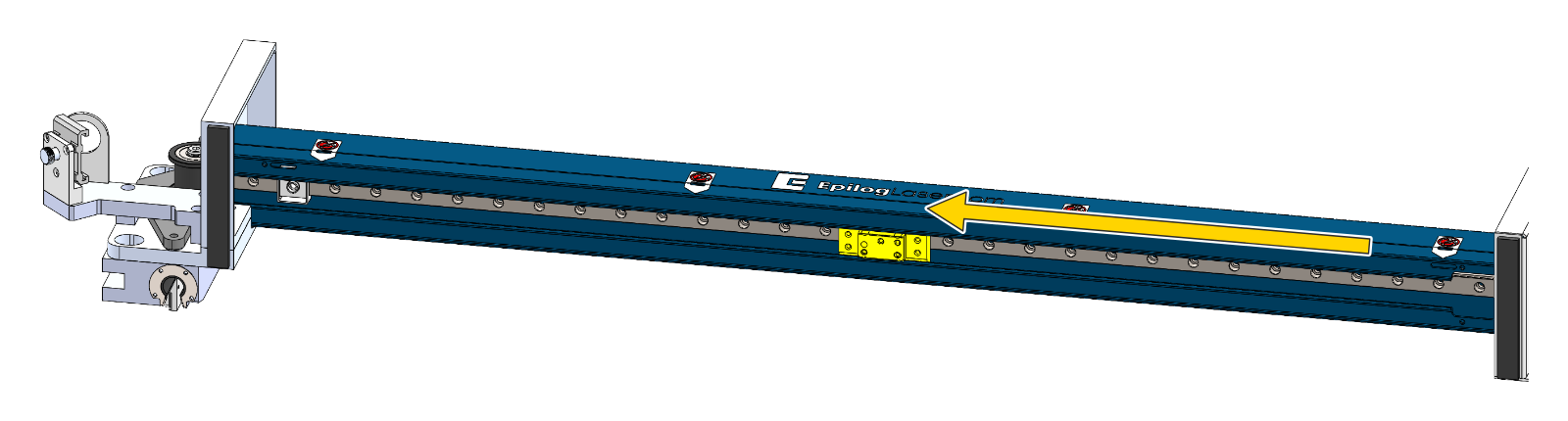
Move the Carriage Plate to the Center
Slide the carriage plate and bearing block back to the center of the X-axis assembly.
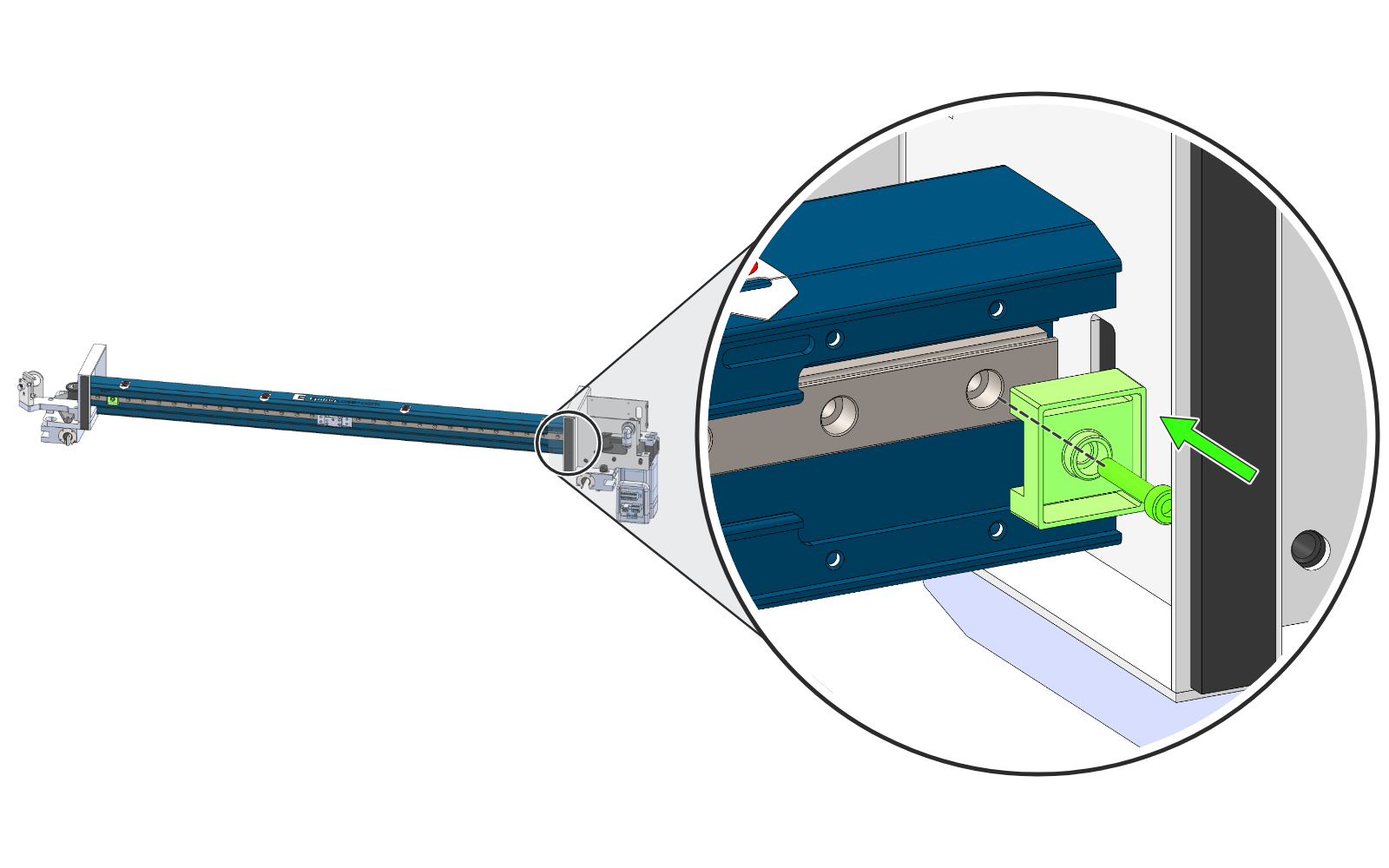
Install the Right Hard Stop
Install the right-hand hard stop over the second-to-last hole of the rail, and secure it with its screw (green).
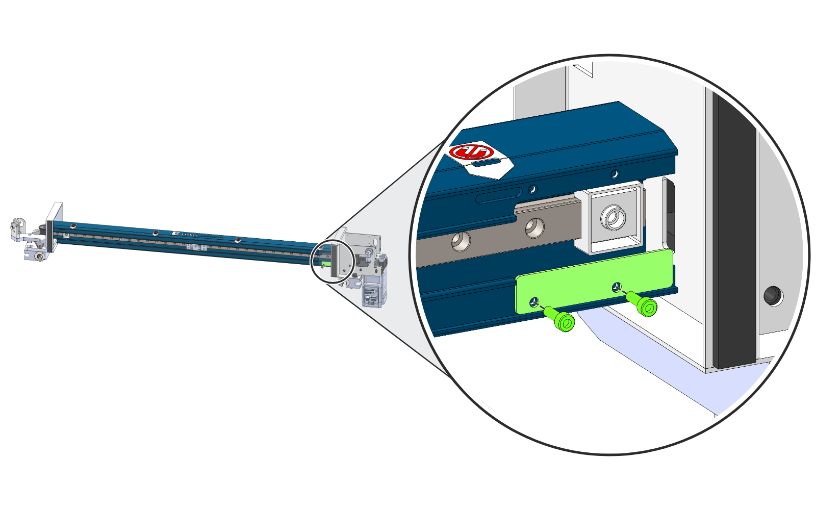
Install the Lower Shield
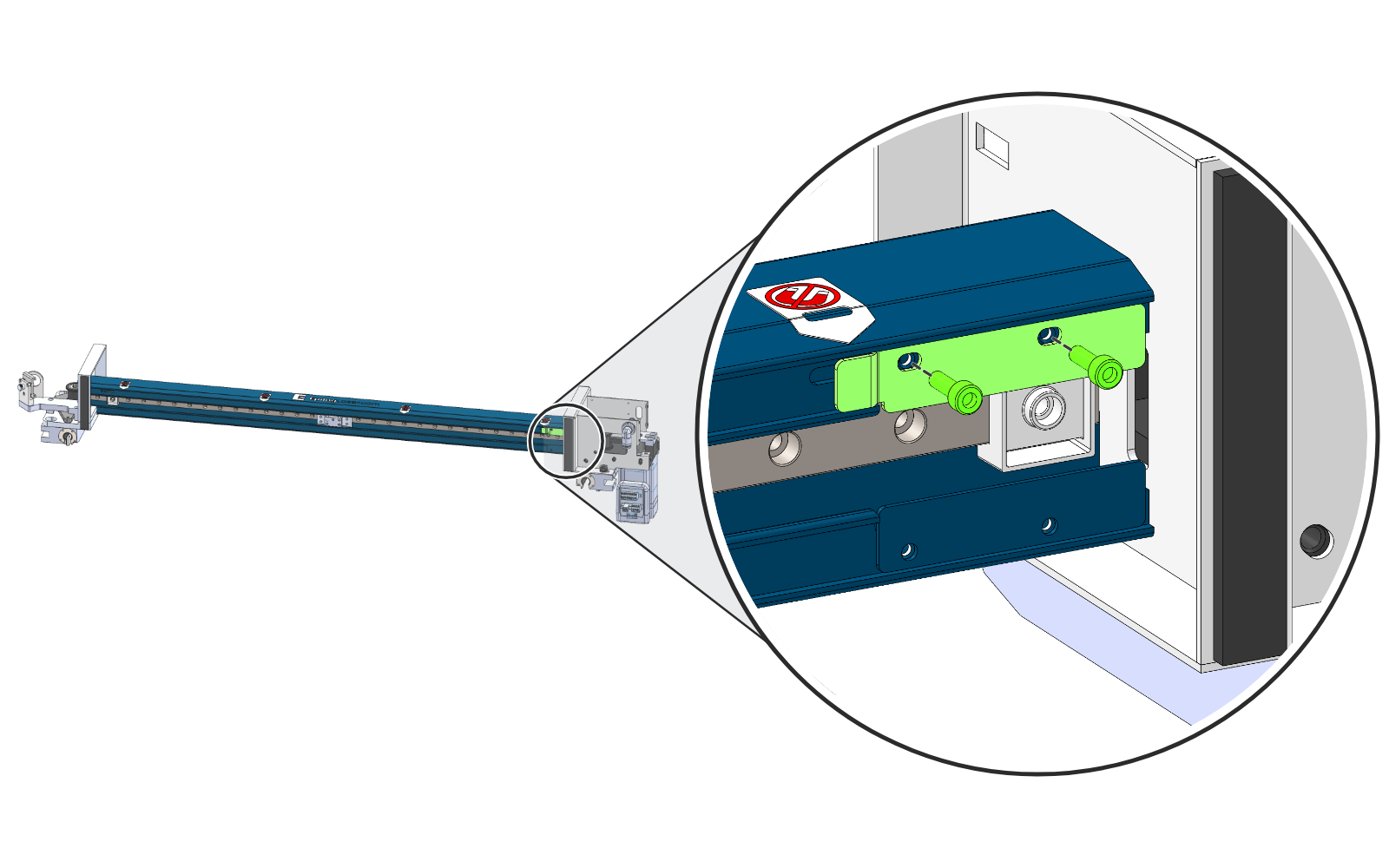
Slide the lower shield back in from the right-hand side and install its two screws (green).
Install the Encoder Strip Clamp
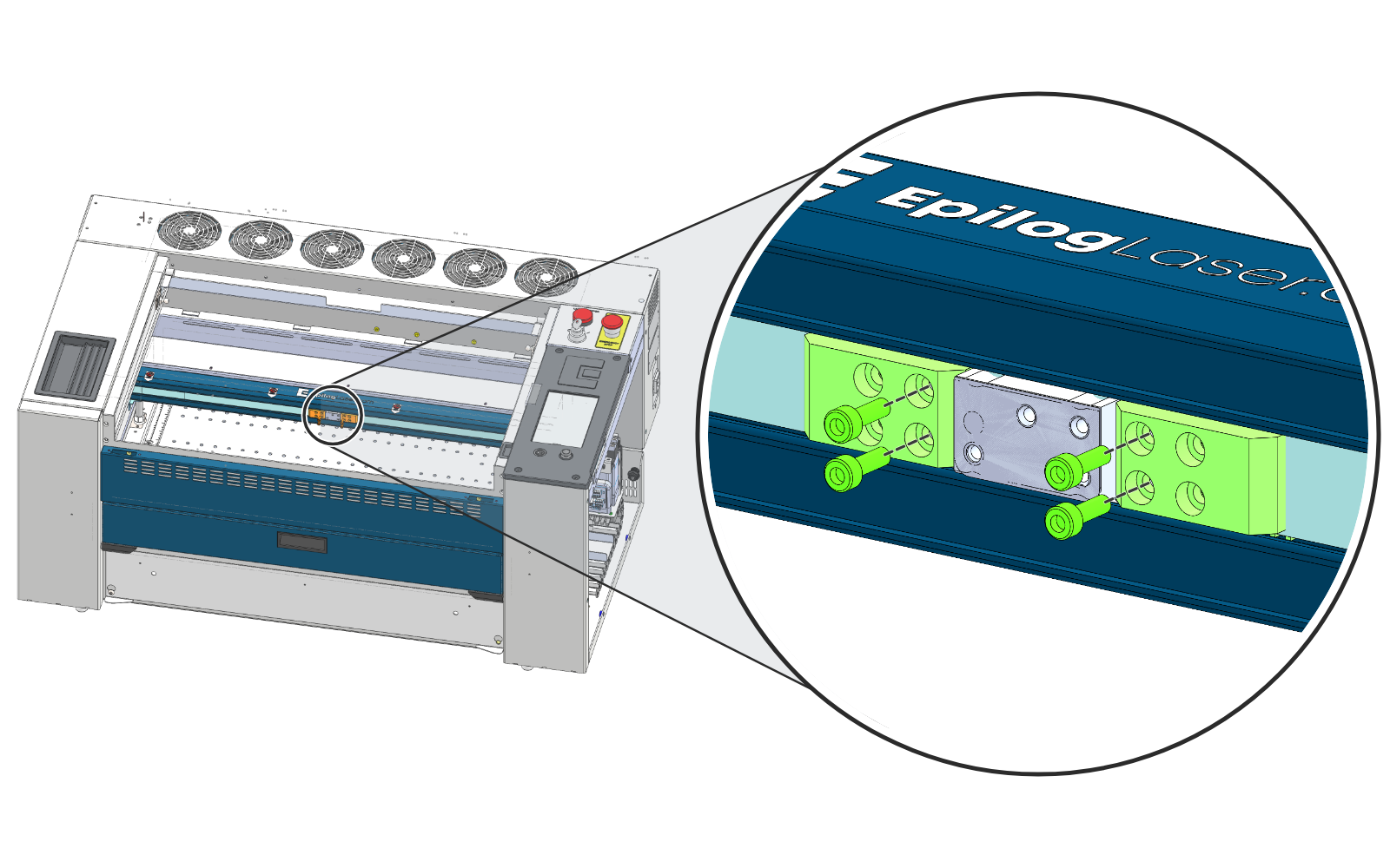
Slide the encoder strip clamp back in from the right-hand side and install its two screws (green).
Install the Belt Clamps
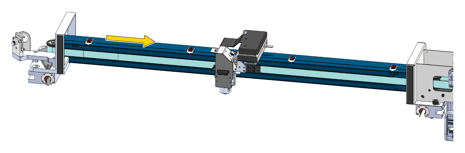
Feed the X-axis belt back into its groove in the front of the X-axis assembly, then install the belt clamps onto the carriage plate with their four screws (green).
Slide the Lens Carriage onto the Plate
Slide the lens carriage to the right, onto the carriage plate.
Install the Lens Carriage Screws
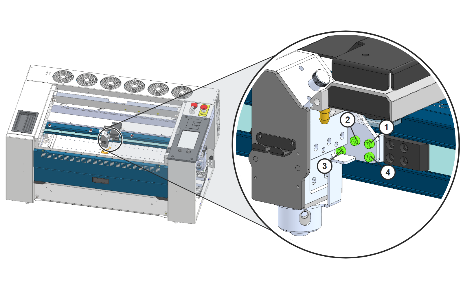
Align the lens carriage with the carriage plate and install the four screws (green) in the order shown, 1 to 4.
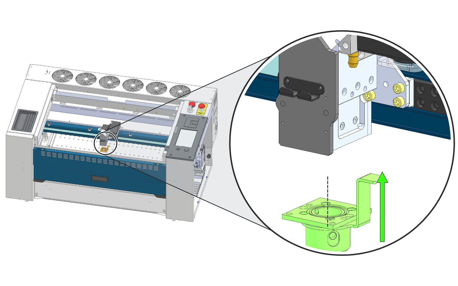
Install the Air Assist Cone
Install the air assist cone on the bottom of the lens carriage.
Finishing Up
Tension the X-Axis Belt
Tension the X-axis belt using the Epilog belt tensioning tool, then tighten the three Allen screws. See the X-Axis Belt Tensioning Guide for the full procedure.
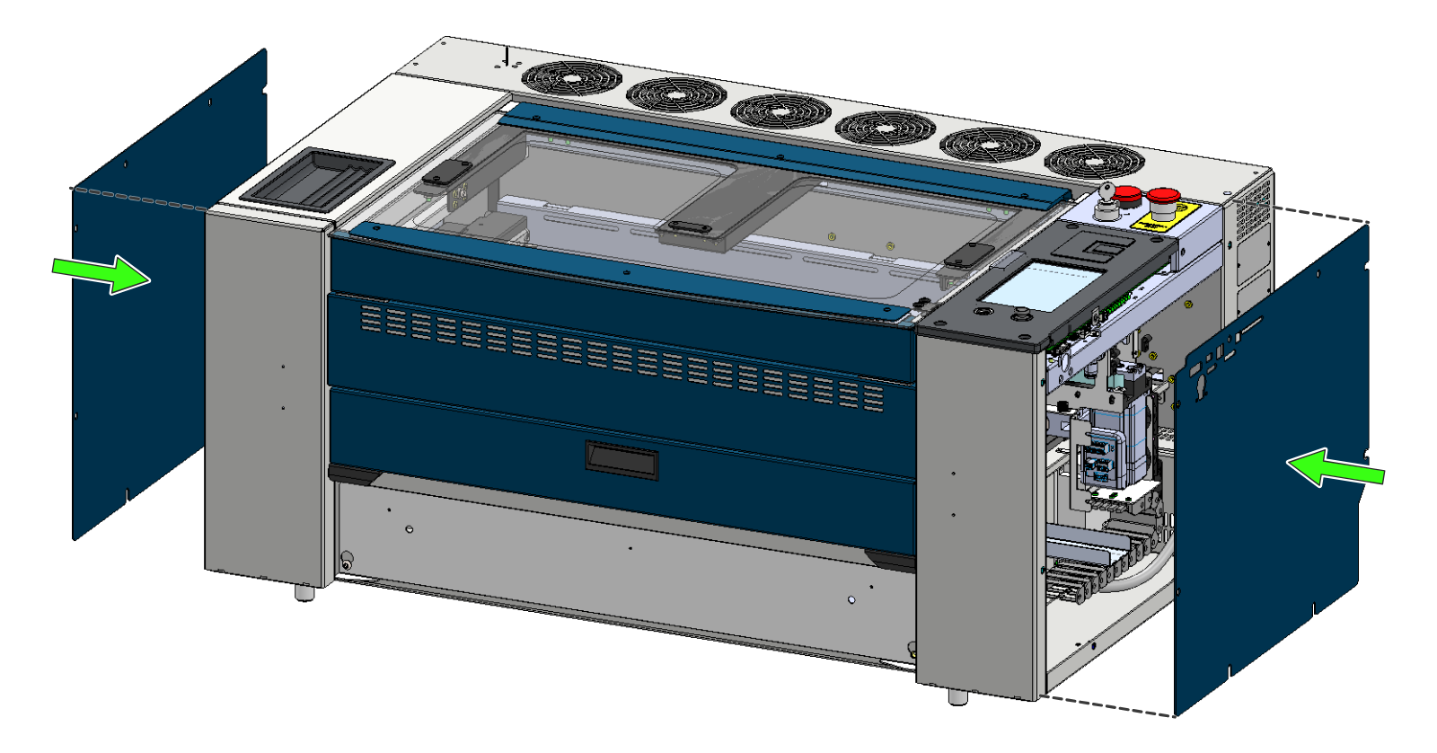
Install the Side Panels
Install the left-hand side panel, then the right-hand side panel, and close the top door.