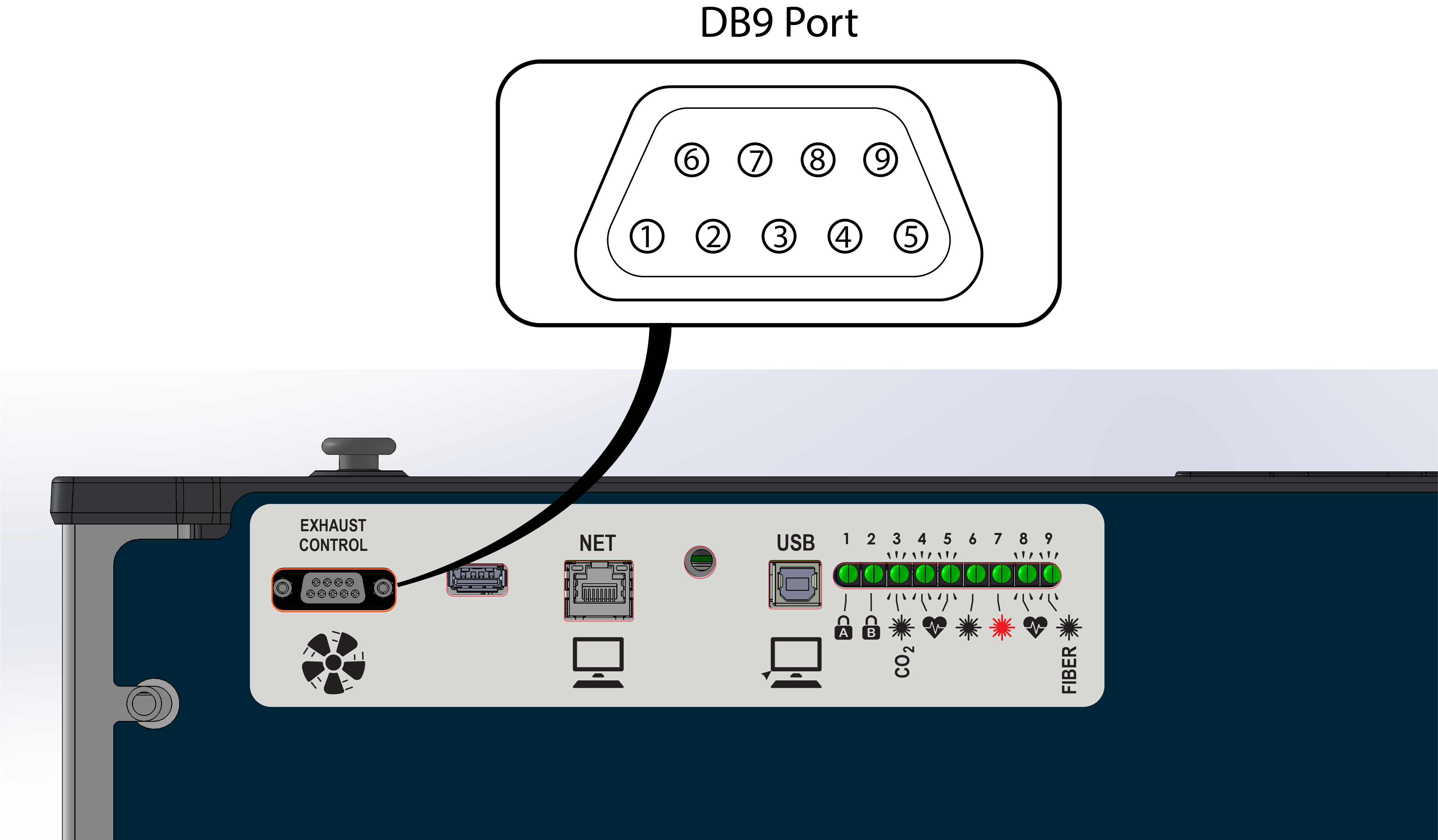
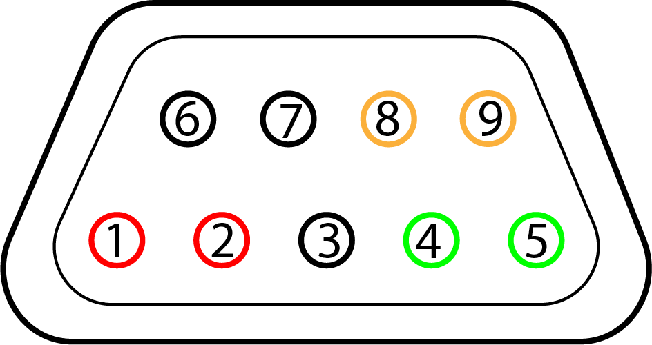
Epilog Fusion Maker, Edge, Pro, and Galvo laser systems include a DB9 port on the right side of the control panel for managing external filtration systems. These signals are automatically assigned based on the selected filter type in the Epilog control panel.
Currently, Epilog officially supports two filtration systems: Filtrabox and BOFA. Other filter systems may be compatible as long as you know the pin requirements and wiring logic of the unit you’re integrating.
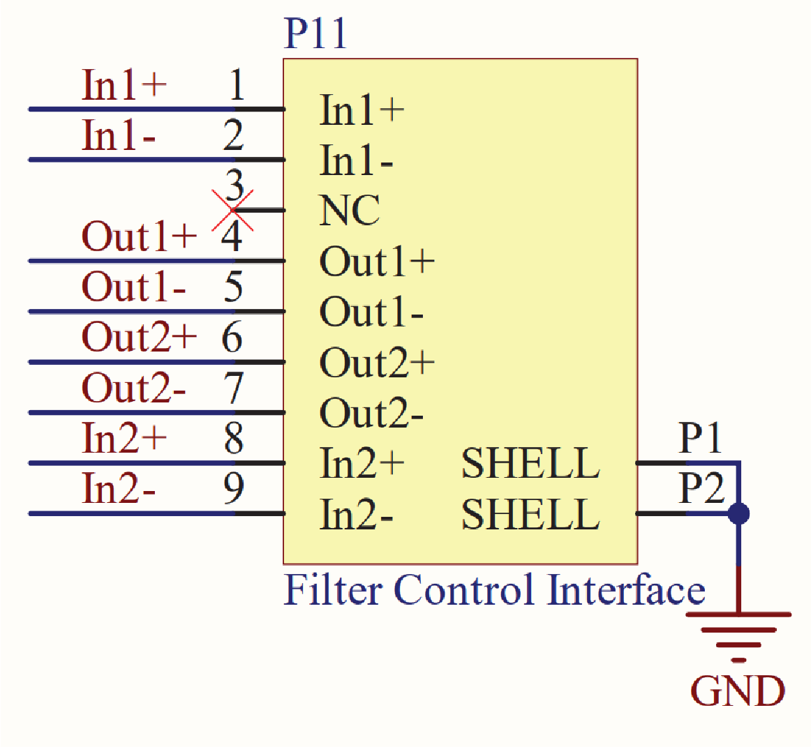
Connector Pinout and Layout
Each pin on the DB9 port is labeled 1–9, with functions that change based on the selected filter type.
DB9 Pin Reference Table (General)
| Pin | Signal Name | Type | Typical Usage (Varies by Configuration) |
|---|---|---|---|
| 1 | Input 1 (IN1+) | Input | Critical Error or “System Failure” input from filter (e.g. BOFA) |
| 2 | Input 1 Return (IN1−) | Input GND | Return for Input 1 |
| 3 | N/C | Reserved | Do Not Connect |
| 4 | Output 1 (OUT1+) | Output | Start filter signal (e.g. Filtrabox / BOFA start command) |
| 5 | Output 1 Return (OUT1−) | Output GND | Return for Output 1 |
| 6 | Output 2 (OUT2+) | Output | Optional/custom use output |
| 7 | Output 2 Return (OUT2−) | Output GND | Return for Output 2 |
| 8 | Input 2 (IN2+) | Input | Low Pressure Detected or “Check Filter” signal (e.g. Filtrabox / BOFA) |
| 9 | Input 2 Return (IN2−) | Input GND | Return for Input 2 |
Note: Signal directions are relative to the Epilog system. Assignments change based on the selected filter type.
Warning: Do not apply voltage to any of the input pins on the DB9 connector. These are monitored by the laser system using low-current sensing circuits. Applying external voltage may cause permanent damage.
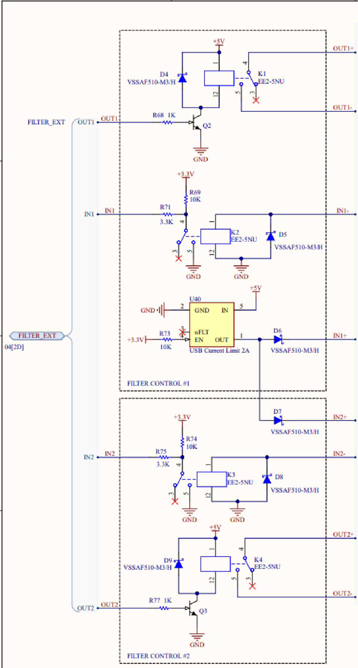
The output pins are controlled by internal relay contacts (EE2-5NU). These contacts are rated for low-voltage control signals. To prevent damage and ensure reliable operation, do not exceed 24V AC/DC and 100 mA across any output pin pair.
Wiring Diagram – Epilog Controller
Filter-Specific Pin Configurations
Filtrabox and BOFA
Both Filtrabox and BOFA filtration systems use the same pin assignments for filter activation and status monitoring.
| Pin Pair | Function |
|---|---|
| 1 & 2 | “Critical Error” signal to Epilog (connected together when filter needs attention) |
| 4 & 5 | Start filter (closed when job begins) |
| 6 & 7 | Reserved output pins (not used by BOFA or Filtrabox systems) |
| 8 & 9 | “Low Pressure” signal to Epilog (connected together when filter needs attention) |
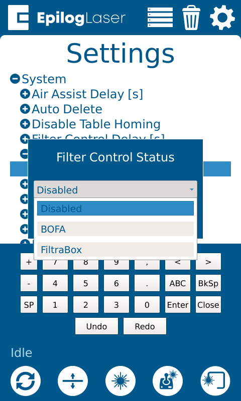
Selecting Filter Type in the Epilog Control Panel
Follow these steps to configure your machine for external filter control:
-
From the home screen, tap the Gear icon to open Settings.
-
Select the Gear + Wrench + icon.
-
Select System.
-
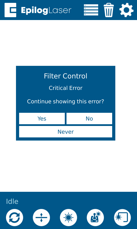
Select Filter Control Status.
-
Select Disabled.
-
Select Filter Type from the list of options.
-
The system will apply the correct pin configuration for the selected model.
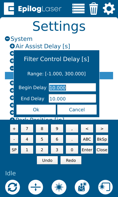
Behavior and Timing
-
When a job starts, pins 4 & 5 close to start the filter.
-
When the job ends or is canceled, the connection opens to shut the filter off.
-
In the same settings menu, you can configure a Filter Control Delay to run the filter before/after jobs.
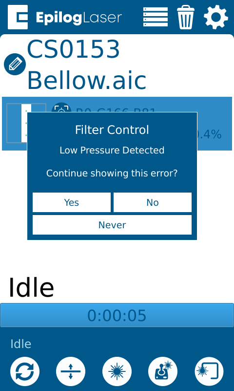
-
When a filter issue is detected, the filtration unit will connect pins 8 & 9, triggering a “Low Pressure Detected” message on the Epilog UI.
-
-
When a filter failure is detected, the filtration unit will connect pins 1 & 2, triggering a “Critical Error” message on the Epilog UI.
-