
Estimated time: 60–90 minutes • Skill: Intermediate
This guide outlines the procedure for replacing CO₂ and 120-Watt laser tubes, as well as the RF unit, on Epilog laser systems. Following these steps ensures the components are removed, installed, and connected safely and correctly.
For this procedure, you will need the replacement parts: CO₂ Laser Tube, 120-Watt Laser Tube, or RF Unit. You will also need the following tools: Phillips Head Screwdriver, and a 5/32″ Hex Wrench.
CO₂ Laser Tube Replacement
Removal
- Power off and disconnect.
Turn off the engraver and disconnect it from power.
- Remove the laser bay access panel.
- Disconnect the data cable.
Located on the left side of the laser tube.
- Disconnect the main harness connection.
Follow the laser harness and disconnect it from the engraver’s main electrical harness. Do not unscrew the harness from the tube; it stays connected when sent to the factory.
- Loosen the mounting screws.
Three green-capped Phillips captive screws (one left, two right). These screws are captive and will pop away from the bracket when loosened.
- Slide the tube left to disengage guide pin.
- Remove the tube.
Carefully lift the tube from the engraver.

Image 1: Access panel removed.
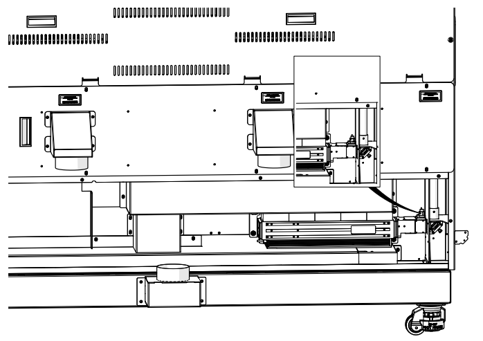
Image 2: Red dot harness disconnected.
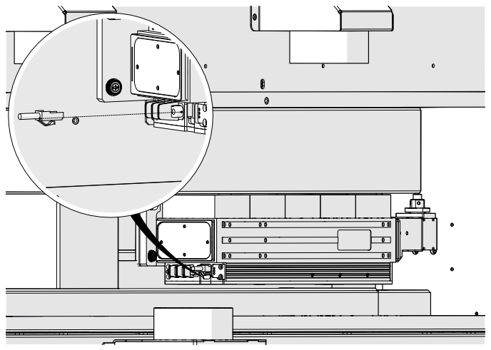
Image 3: Data cable disconnected.
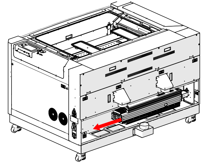
Image 4: Disconnect electrical harness.
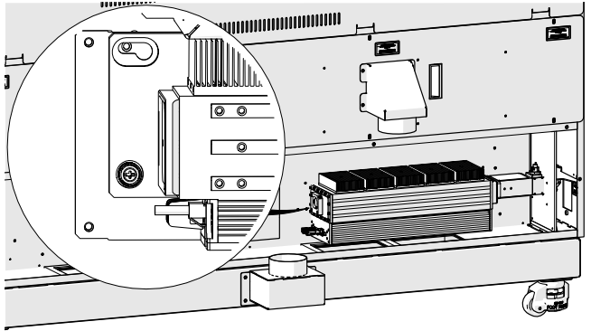
Image 5: Left bracket screw loosened.
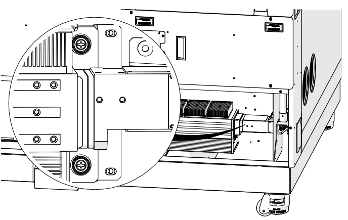
Image 6: Right bracket screws loosened.
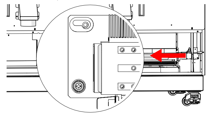
Image 7: Tube cleared from guide pin.
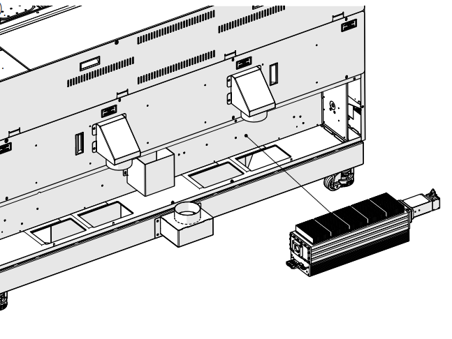
Image 8: Tube removed.
Installation
- Install the tube.
Align the guide pin with the left bracket opening.
- Engage the guide pin.
Slide the tube right to lock it in place.
- Tighten mounting screws.
Three green-capped screws (one left, two right).
- Connect power harness.
Connect the laser harness to the main electrical harness.
- Connect data cable.
- Reconnect power and turn on engraver.
Complete the laser alignment and focus calibration procedures.
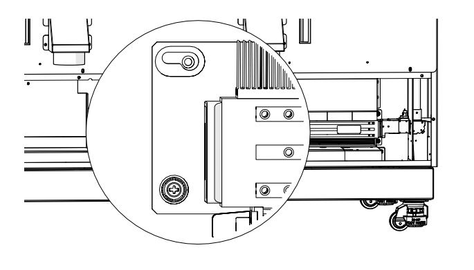
Image 9: Tube installed.
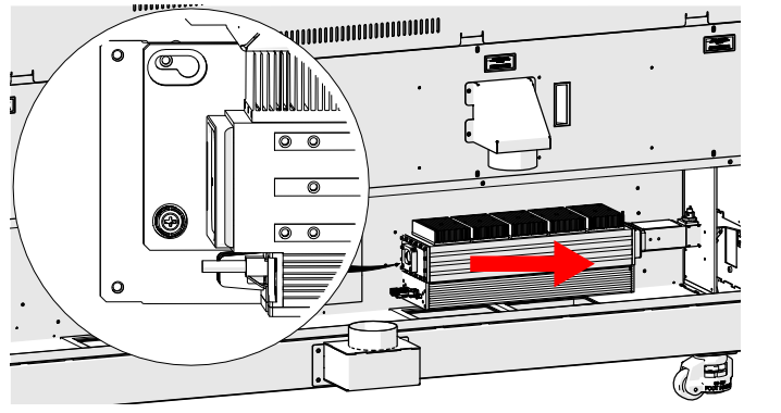
Image 10: Tube on guide pin.
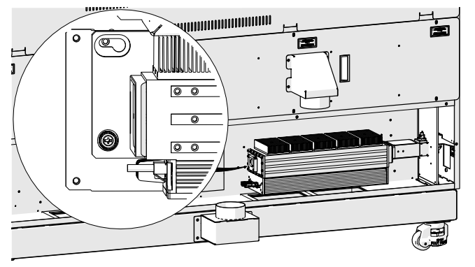
Image 11: Left bracket screw.
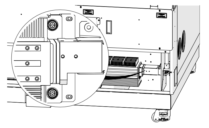
Image 12: Right bracket screw.
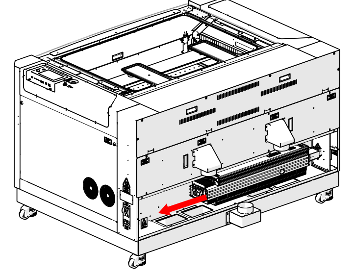
Image 13: Electrical harness connected.
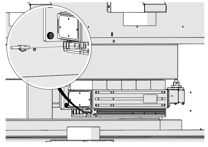
Image 14: Data cable connected.
120-Watt Laser Tube Replacement
Removal
- Power off and disconnect.
- Remove laser bay access panel.
- Disconnect red dot harness.
- Loosen and remove coaxial cable.
- Loosen mounting screws.
Six green-capped Phillips screws (three left, three right).
- Remove the tube.
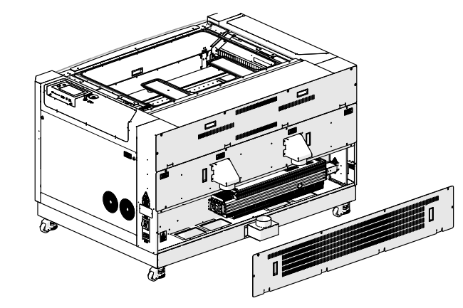
Image 15: Access panel removed.
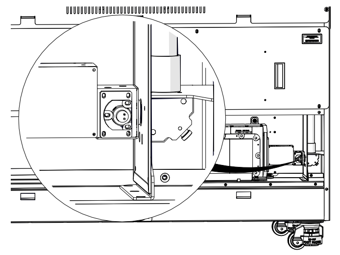
Image 16: Red dot harness disconnected.
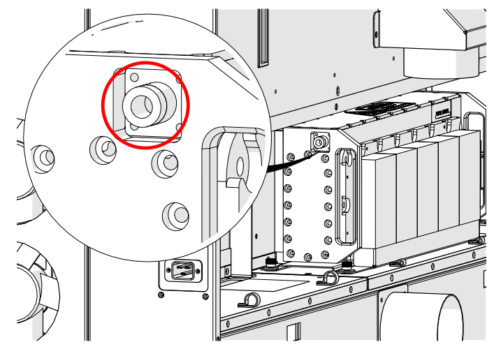
Image 17: Coaxial cable location.
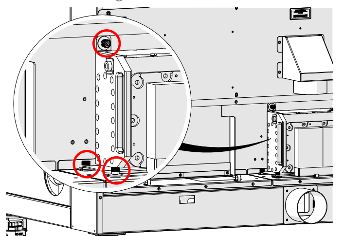
Image 18: Left captive screw locations.
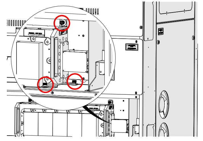
Image 19: Right captive screw locations.
Installation
- Place tube in engraver.
Align screws over chassis openings.
- Tighten mounting screws.
- Connect coaxial cable.
Finger tight, rock side to side to secure.
- Connect red dot harness.
- Reconnect power and turn on engraver.
Complete laser alignment and focus calibration procedures.
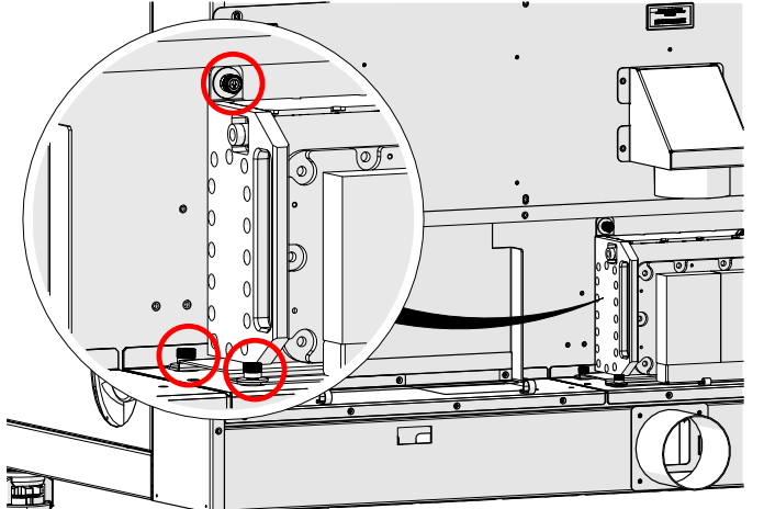
Image 20: Left captive screw locations.
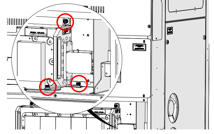
Image 21: Right captive screw locations.
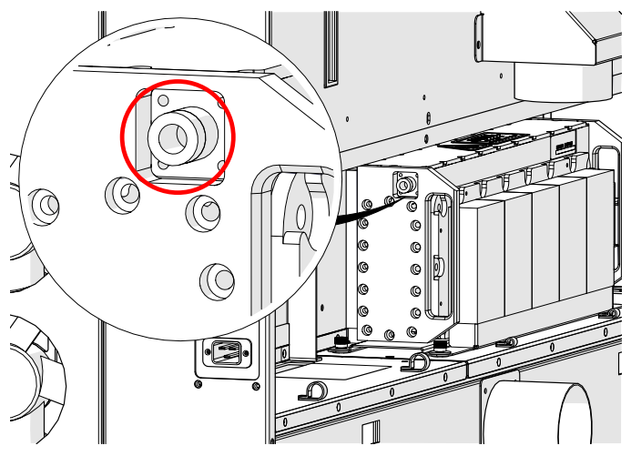
Image 22: Access panel removed.
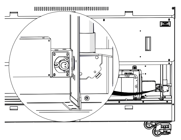
Image 23: Red dot harness connection.
RF Unit Replacement
Removal
- Power off and disconnect.
- Remove laser bay access panel.
- Disconnect data cable.
- Disconnect power harness.
Remove three Allen screws securing grounding wires. Positions are interchangeable.
- Loosen coaxial cable.
- Loosen mounting screws. Two green-capped Phillips screws.
- Remove RF unit.
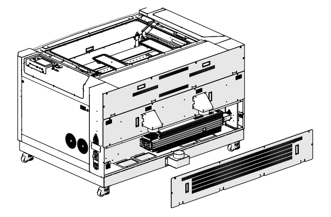
Image 24: Laser bay panel removed.
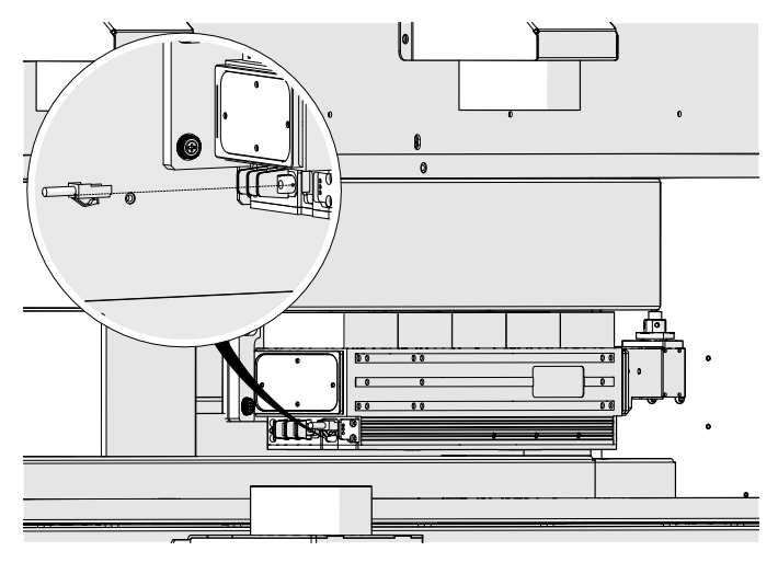
Image 25: Data cable connection.
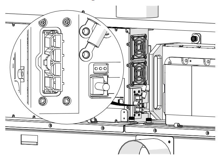
Image 26: Red dot harness connection.
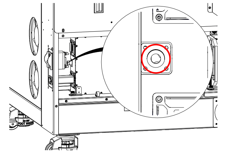
Image 27: Coaxial cable connection.
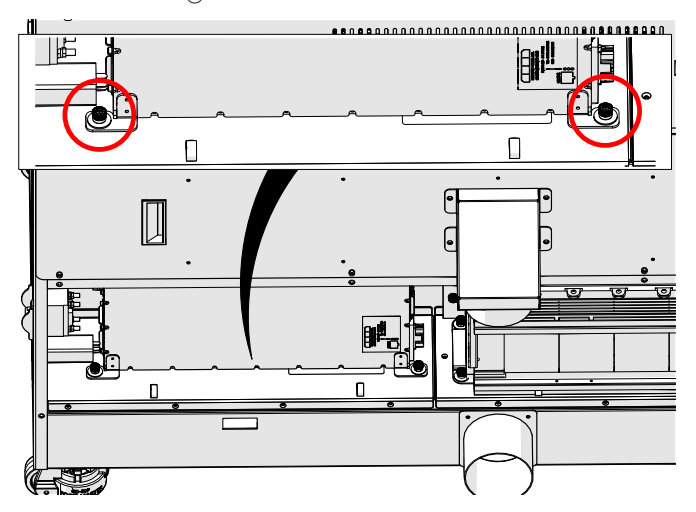
Image 28: Green RF mounting screws.

Image 29: RF removed.
Installation
- Place RF unit in engraver.
Align screws over chassis openings.
- Tighten mounting screws.
- Connect coaxial cable.
Finger tight, rock side to side to secure.
- Connect power harness.
Install and tighten three Allen screws for grounding wires.
- Connect data cable.
- Install laser bay access panel.
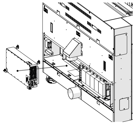
Image 30: RF Installed.
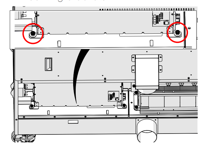
Image 31: RF mounting screws.
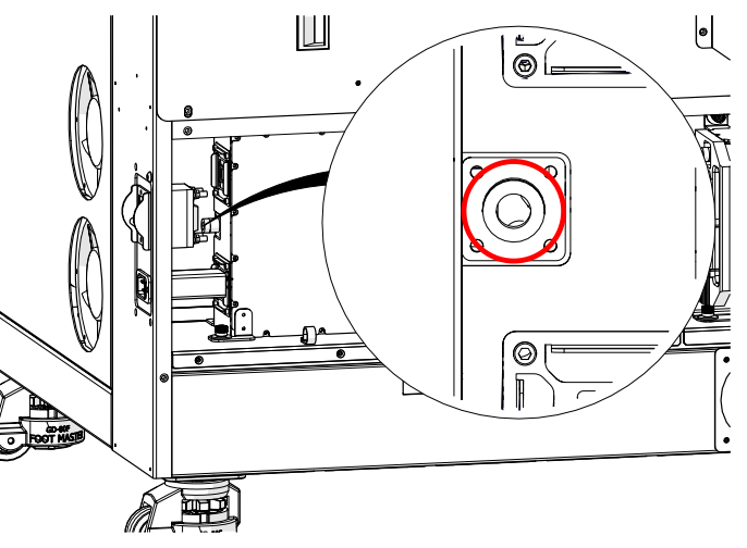
Image 32: Coaxial cable on RF.
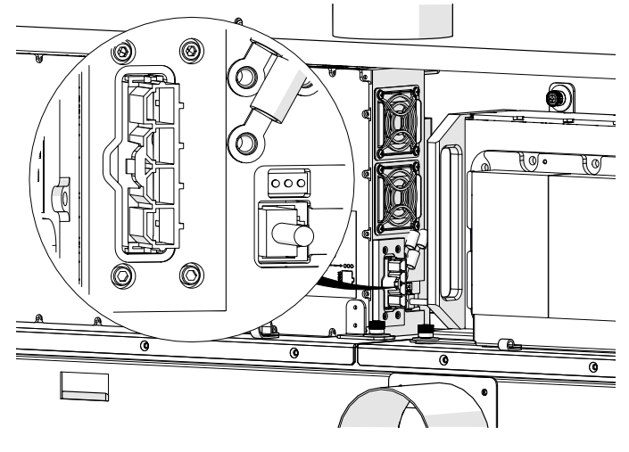
Image 33: RF power harness connection.
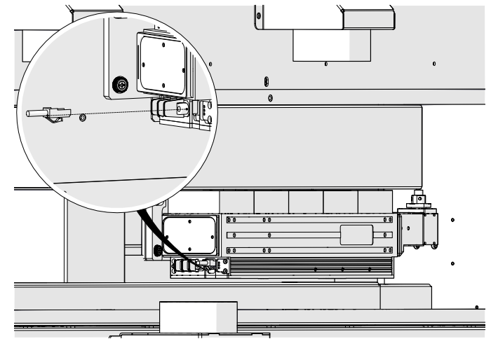
Image 34: RF data cable connection.
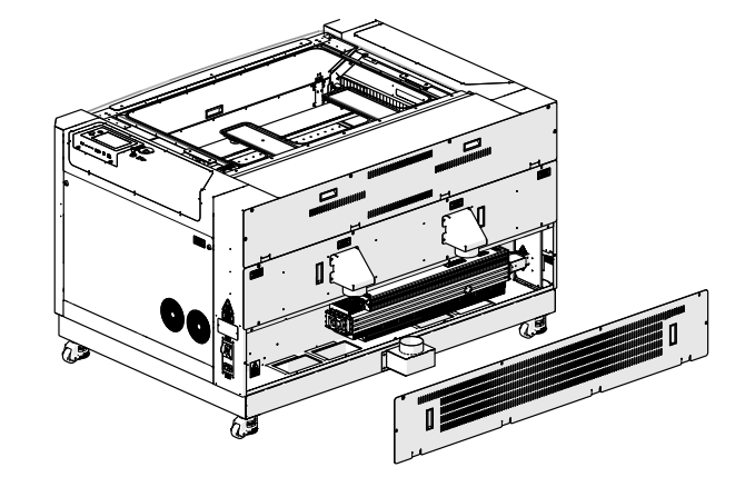
Image 35: Panel installation.
