Estimated time: 20–30 minutes • Skill: Intermediate
This procedure will guide you through the process of removing and replacing the main controller board in a Legend EXT laser system. Following these steps ensures safe handling of sensitive electronics, proper reconnection, and minimal downtime after installation.
Important: Always wear the included anti-static wrist strap when handling the controller board. Static discharge can permanently damage sensitive components.
Note: If your machine can still boot, complete Step 1 before removing the board to save setup time. If it does not boot, skip directly to Step 2 — the new board is pre-programmed with your system settings.
Preparation
-
Record system settings (if the machine boots).
Before removing the controller board, record the following values from the Function and Configuration menus. These will need to be re-entered after installation:To access the Function menu on the engraver, press and hold both the GO and Pointer buttons on the control panel. Press the GO button repeatedly to cycle through the available menu headings.
Setting Current Value Serial Number IP Address Subnet Mask Gateway From the Configuration menu, record the following settings for later re-entry. To cycle through the Configuration menu, press the Right Arrow (▶) on the control panel.
Setting Current Value X-Home Y-Home
Controller Board Removal
-
Power down the engraver.
Turn off the machine and unplug it from the power source before beginning. -
Remove the left side panel.
This provides access to the controller board assembly. -
Disconnect all five electrical connectors.
Carefully unplug each cable from the controller board. -
Remove the controller board screws.
Use a screwdriver to remove the four corner screws securing the board. -
Remove and replace the controller board.
Lift the old board out of the chassis, place the new board in position, and secure it with the four screws.
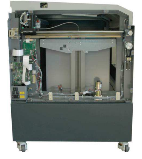
Image 1: Left side panel removed.
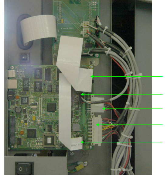
Image 2: Disconnecting electrical connections.
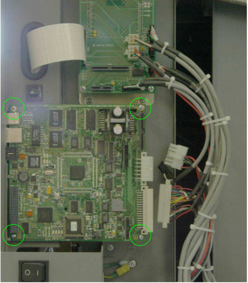
Image 3: Removing controller board screws.
Image 4: New controller board installed.
Controller Board Installation
-
Reconnect all five electrical connectors.
Ensure each cable is firmly seated in its correct port. -
Reinstall the side panel.
Secure the left panel back onto the engraver chassis. -
Power on the machine.
Reconnect power and turn the engraver back on. -
Re-enter saved settings.
Use the values recorded earlier to restore your network and configuration parameters.
Image 5: Reconnecting electrical connections.