In this lesson we’ll walk through replacing the Epilog Mini/Helix Controller Board.
Record Settings
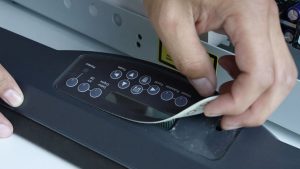
If your machine will boot up, we’ll start by writing down some settings that will save you time later. Press the Go and Pointer button at the same time to access the Function menu and cycle through the headings by pressing the Go button. Write down the Serial Number, IP Address, Subnet Mask and Gateway.


Next, press the Configuration button on the display panel and cycle through the menu by pressing the right arrow. Write down the X-Home, Y-Home, Laser Match, Stamp Match and System Unit.


Remove Right Side Panel
Shut off the laser and remove the power cord from the machine.

Remove the right side panel by removing the 6 screws, 4 located on the side of the machine, two located on the back of the machine.


Equip Static Strap
Put on the anti-static strap. Always wear the anti-static strap when handling the control board to avoid damaging the unit through static discharge. Clip the strap on to any metal part of the machine.


Remove Old Controller Board
Depending on the type of connection you are using to print to the laser, you will need to either disconnect the Ethernet cable or USB cable from the back of the engraver where it plugs into the controller board.

Locate the Controller Board on the right side of the machine towards the rear. Unplug the 4 connectors on the controller board mainly located along the left side if you are looking directly at it.

On newer machines, one of those 4 connectors will have a bracket with 2 Phillips head screws holding the connector in place to secure it to the board. If you have the newer machine, use a Phillips head screw driver to remove the 2 Philips head screws from the bracket so you can unplug the connector.

The older machine does not have that bracket, and only requires removing the light grey connector located on upper left side of the board.


To remove the Controller Board, use the Phillips head screw driver to remove the 4 Philips head screws located on each corner of the board.


Install New Controller Board
Install the new Controller Board, replacing all 4 Philips head screws to each corner of the board.


Reconnect all 4 connectors to the controller board. If you have a newer machine, tighten the 2 Philips head screws on the bracket of the last connector.


Reconnect either the Ethernet cable or USB cable into the Controller Board, whichever you are using to connect to the laser.

Reinstall Right Side Panel
Replace the right panel, tightening all 6 screws.


Plug the machine in and turn it on.