
Estimated time: 60–90 minutes • Skill: Advanced
This guide outlines the procedure for aligning the laser beam inside the Epilog Zing 24 engraver. Following these steps will ensure the optics are properly aligned for consistent laser performance and engraving quality.
SAFETY GLASSES REQUIRED: Always wear safety glasses or protective eyewear throughout this procedure.
Overview
The laser alignment procedure should be performed if you are experiencing any of the following:
- General loss of power.
- Fading in one corner of the table.
- Loss of power in certain table positions.
- Replacement of the X-axis rail, laser tube, or mirror.
- The engraver has been moved or transported.
Safety
Warning: Operating the Zing 24 engraver without side panels installed is hazardous. Always wear protective eyewear and avoid exposure to open laser paths.
Before Starting
Direction:
Unless otherwise stated, all directions (left-hand, right-hand, etc.) are given from the perspective of facing the machine from the front.
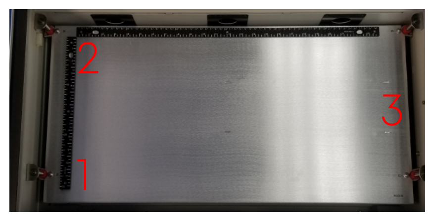
Table Positions:
The table is divided into three alignment positions based on distance from the laser source.
Mirror Locations:
The Zing 24 uses three mirrors and a red dot pointer located under the left side panel.
Note: The Zing 24 alignment procedure is specific to this model. Do not use procedures for other Epilog systems (e.g., Zing 16), as they will result in incorrect alignment.
Pre-Alignment Procedure
- Disable the gantry.
Press the X/Y OFF button on the Zing keypad to unlock the gantry and move it to an accessible area.
- Prepare the target.
Place masking tape over the front side of the alignment target and insert it into the lens assembly.
- Return to park position.
Press the RESET button to move the gantry and lens carriage to the park position.
- Create a test file.
In your design software, create a new 24″ × 12″ file. Draw a ½” × ½” vector square near the lower left corner (1–2″ from both edges). Set speed to 10% and power to 10%.
Note: If using the Epilog Software Suite, the file will import with correct dimensions automatically.
- Send the job to the engraver.
- Run the job and pause.
While keeping one hand on the lid, press GO to start. When a burn mark appears on the tape, open the lid to stop the laser and press STOP.
Note: The laser only fires when the lid is closed.
- Pause the job.
Press STOP once to pause, leaving the carriage in the lower-left position (Position #1).
- Inspect the burn mark.
If centered, proceed to Adjusting Mirror #2. If off-center, continue to Adjusting Mirror #1.
Adjusting Position / Mirror #1
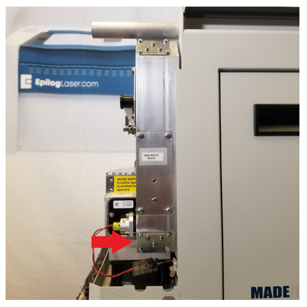
- Remove the left side panel.
Remove four Phillips screws—three on the side and one at the rear. Pull the bottom of the panel out and lift up to remove it.
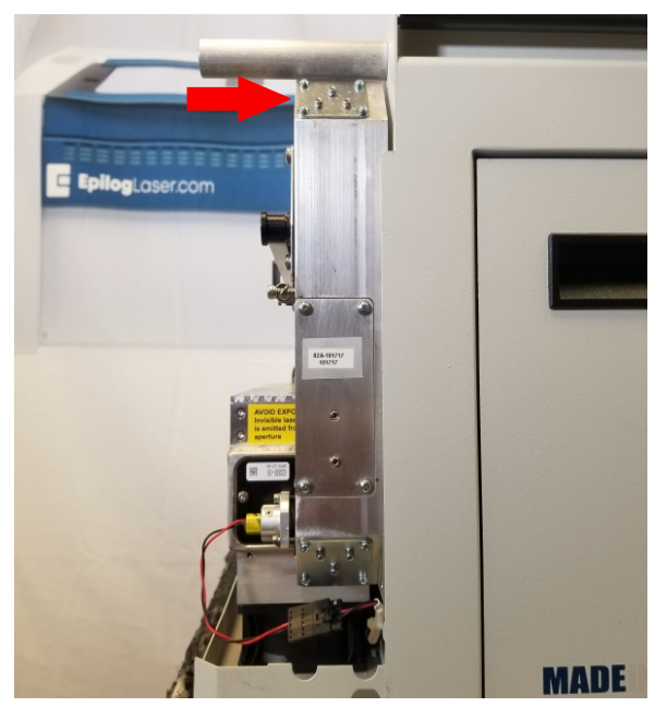
- Locate Mirror #1.
Found at the bottom of the laser periscope.
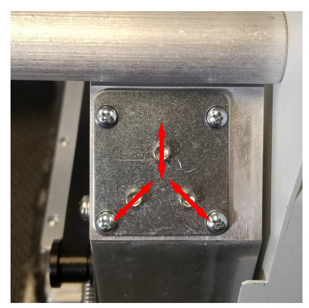
- Adjust Mirror #1.
Use the three 3/32″ Hex screws to move the laser/red dot on the target. Each screw moves the beam in a specific direction.
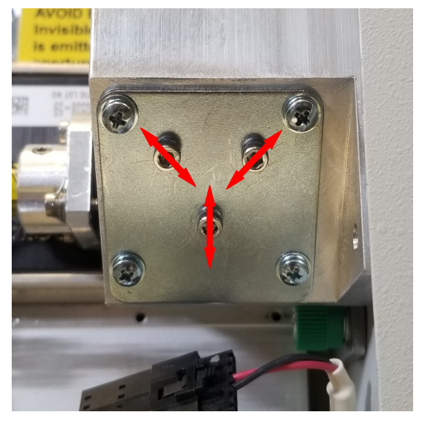
Image 6:Mirror #1 location beneath the laser periscope. Note: Make small adjustments. Large movements may cause the red dot or laser beam to go off target. If the laser is lost, contact Epilog Support.
- Turn on the red dot diode.
Press POINTER on the keypad. Use the red dot’s position to gauge mirror adjustments. Move the red dot half the distance of the laser offset to correct aim.
- Re-test and refine.
After each adjustment, replace the tape, run the test file again, and observe the burn mark. Repeat until centered.
- Lock in alignment.
Once centered, apply a small dab of super glue to each adjustment screw to secure the setting.
Adjusting Position / Mirror #2 & Red Dot
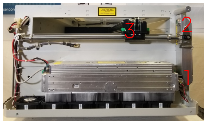
- Locate Mirror #2.
At the top of the laser periscope.
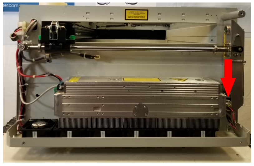
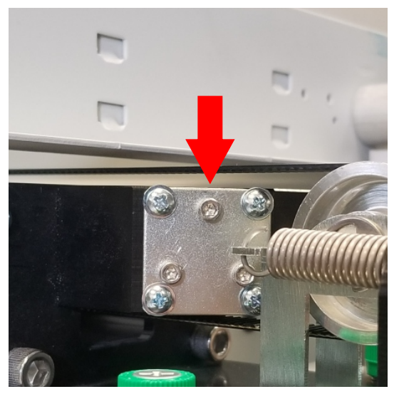
- Locate the red dot diode.
Located at the front of the laser tube.
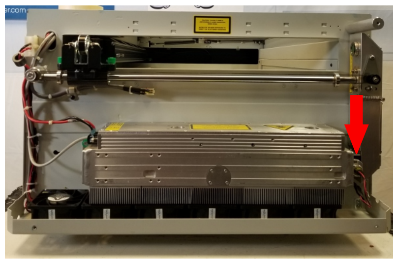
Image 9:Red dot diode locations. 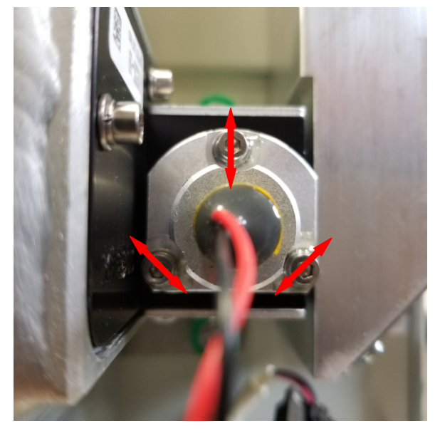
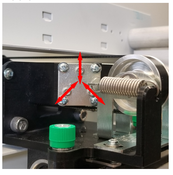
Image 10:Red dot diode adjustment screw locations. - Create a new test file.
24″ × 12″ file with ½” vector square near the top-left corner. Use 10% speed and power.
- Run the job and pause.
When the burn appears, open the lid to stop laser fire and press STOP to leave the carriage in Position #2.
- Align the red dot.
Turn on the red dot diode and adjust its screws so the dot aligns with the burn mark.
- Center the beam.
Use Mirror #2’s screws to move both the red dot and CO₂ beam to the target center. Then secure the screws with adhesive.
Adjusting Position / Mirror #3
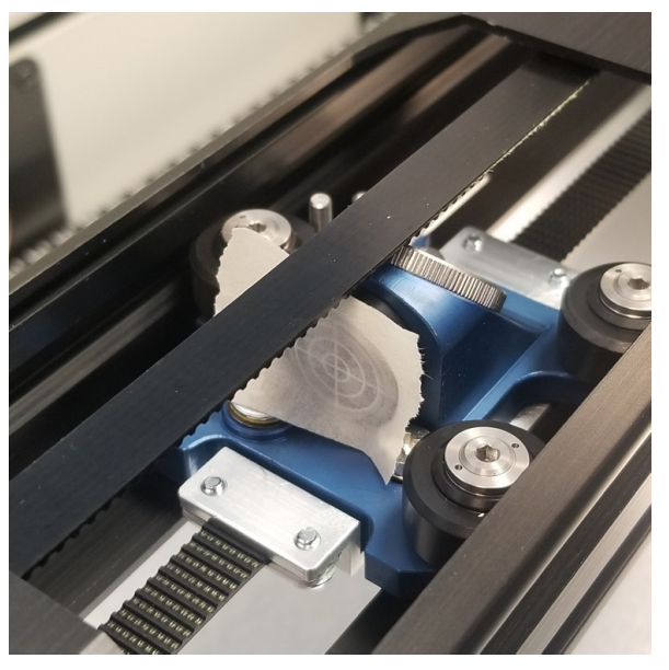
- Locate Mirror #3.
On the left side of the gantry.
- Move to Position #3.
Press X/Y OFF and manually move the carriage to Position #3.
- Adjust Mirror #3.
Use the 3/32″ Hex screws on mirror #3 to align the red dot to the target center, then secure with adhesive.
- Turn off the red dot.
Press POINTER to disable the diode.
- Reinstall the side panel.
Reattach the left side panel and secure with screws.
Conclusion
This completes the CO₂ laser alignment procedure for the Epilog Zing 24 engraver. Verify consistent burn marks at all three table positions to confirm proper alignment.
