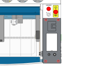
Sicherheit geht vor: Stellen Sie sicher, dass das Lasersystem vollständig ausgeschaltet ist und das Netzkabel aus der Steckdose gezogen wurde, bevor Sie interne Elektronikteile berühren oder trennen. Berühren Sie keine freiliegenden Komponenten des Netzteils.
Wichtig: Die Steuerplatine, die Backplane und andere elektronische Komponenten sind empfindlich gegenüber elektrostatischer Entladung (ESD). Tragen Sie vor dem Umgang mit diesen Komponenten stets ein antistatisches Armband, das mit dem blanken Metallgehäuse des Geräts geerdet ist, um Schäden zu vermeiden.
Teil 1: Ausbau der Steuerplatine
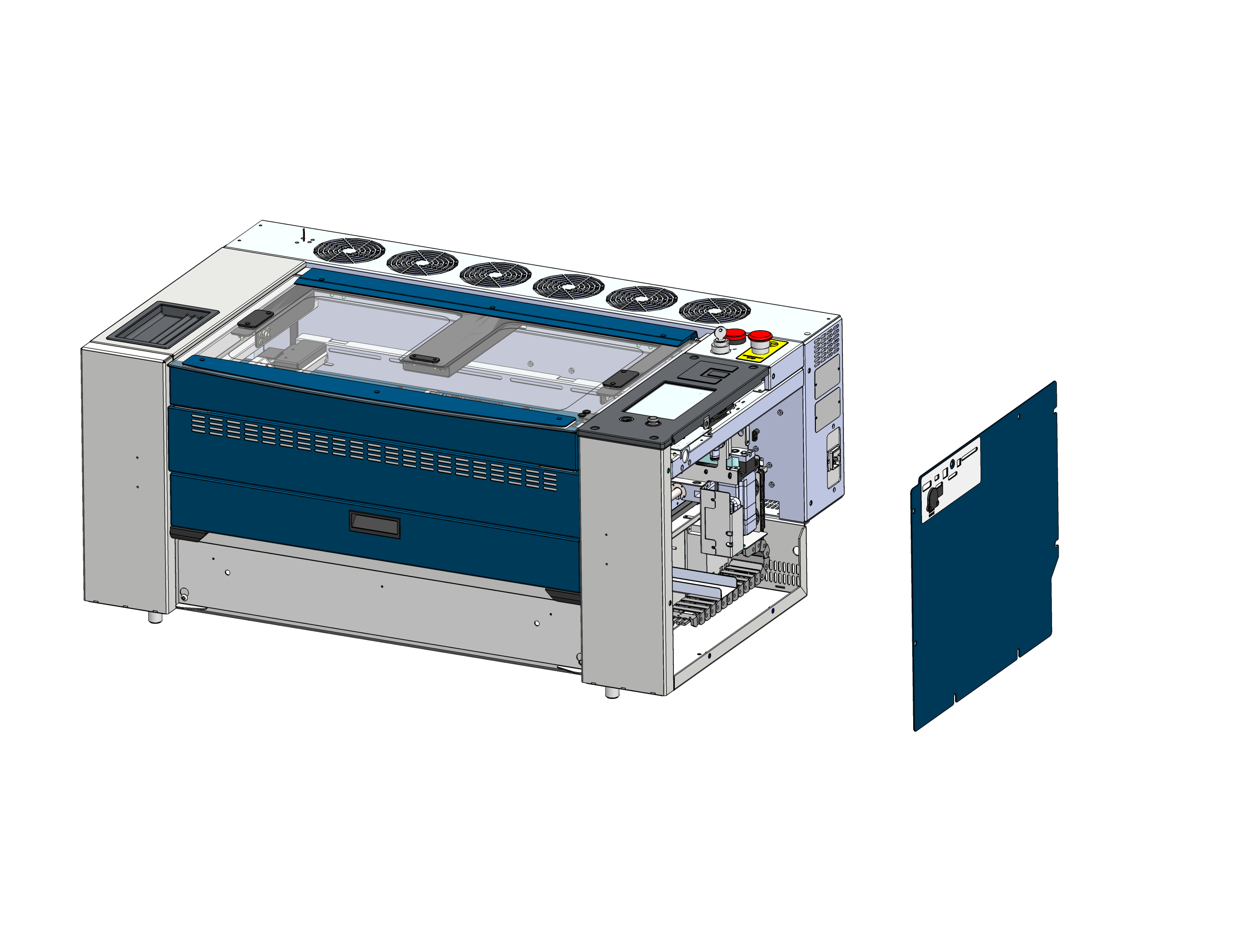
Seitenteil entfernen
Suchen Sie die rechte Seitenabdeckung des Lasergehäuses und entfernen Sie sie, um Zugang zur Elektronik zu erhalten.
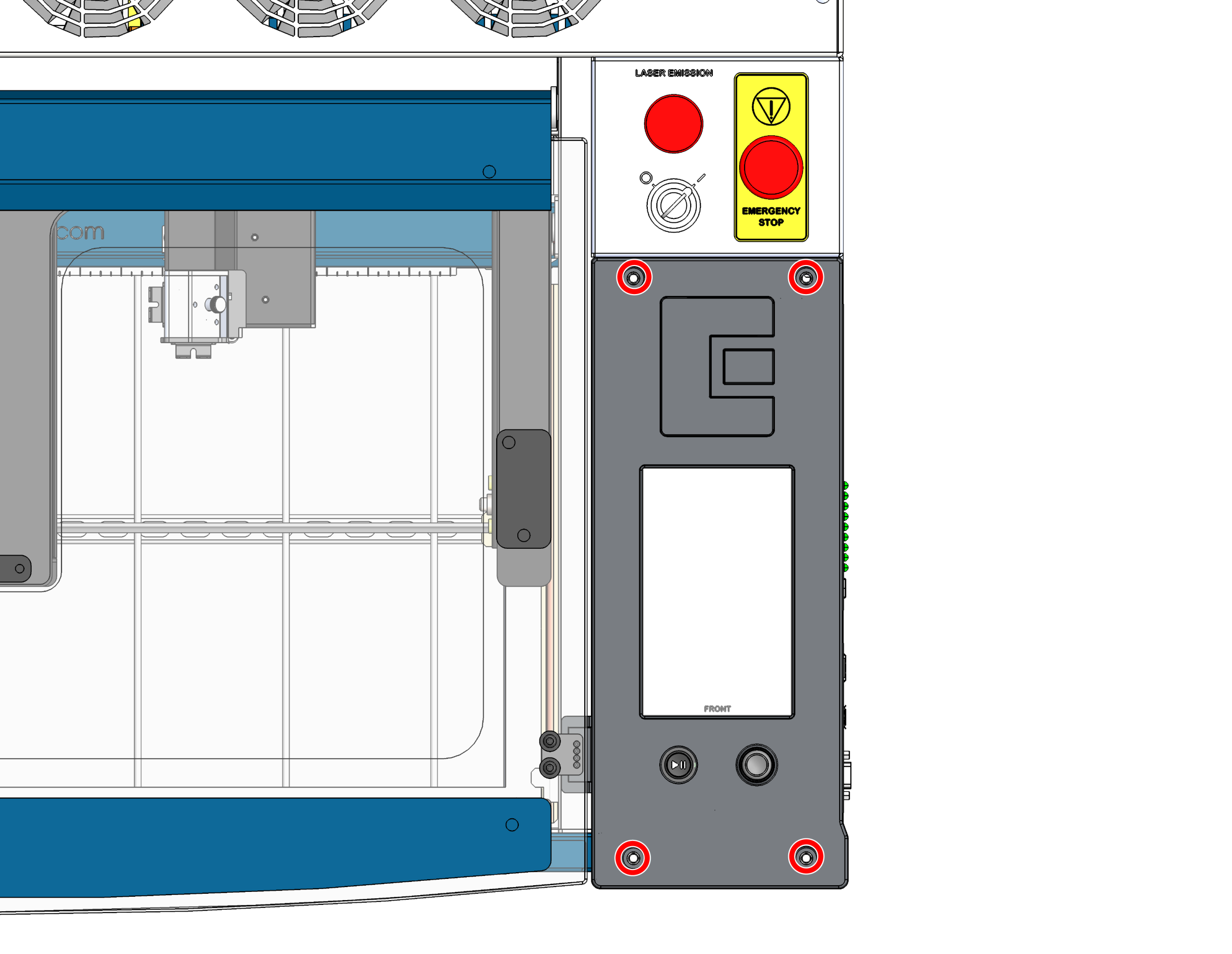
Schrauben der Steuerplatine entfernen
Lösen Sie die 4 Schrauben, mit denen die Steuerplatine am Gehäuse befestigt ist.
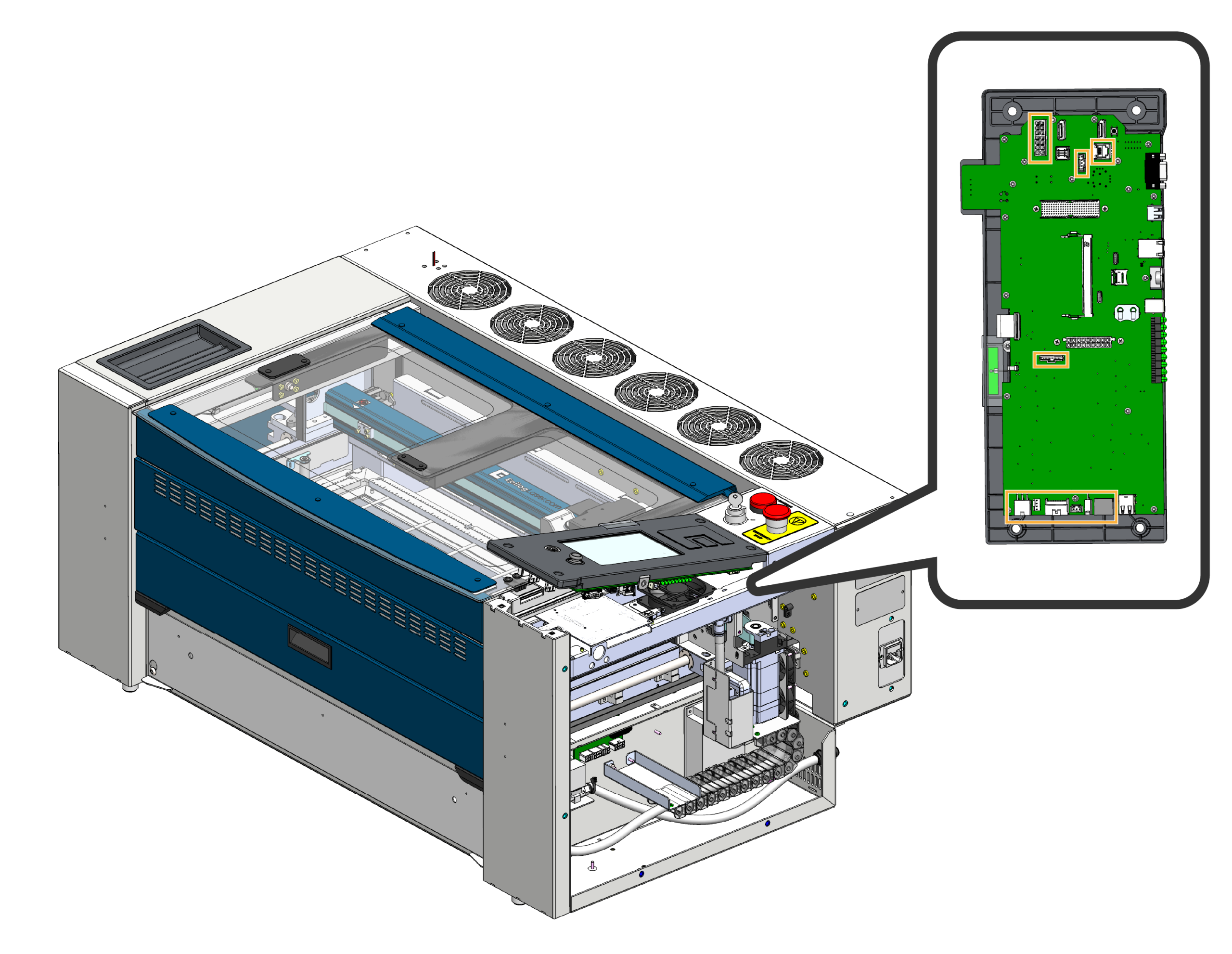
Kabelbaum abklemmen
Kippen Sie die Vorderseite der Steuerplatine vorsichtig nach oben und ziehen Sie die an der Steuerplatine angeschlossenen Kabelbäume ab.
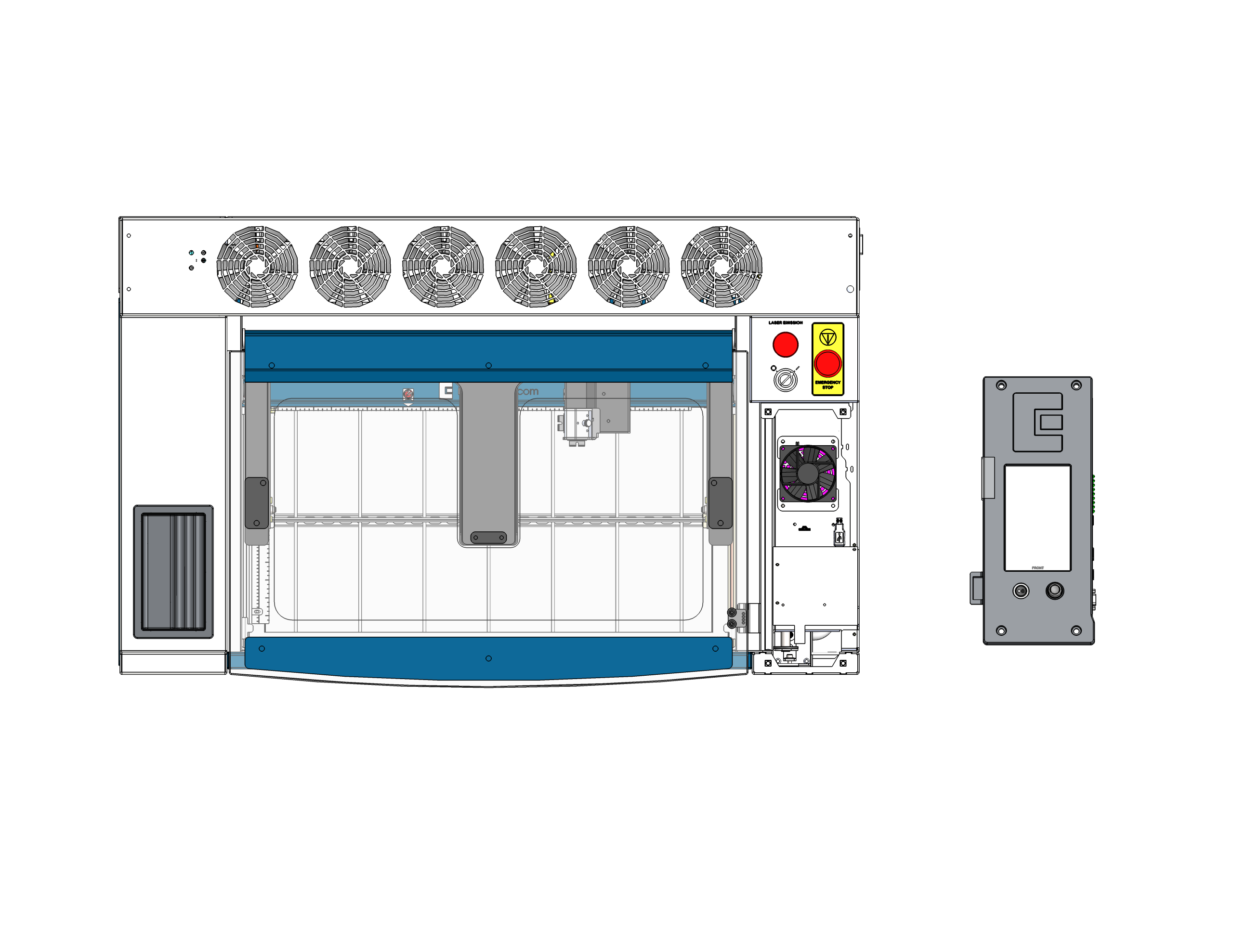
Steuerplatine entfernen
Entnehmen Sie die Steuerplatine aus dem Gerät und nehmen Sie sie vollständig heraus. Legen Sie sie mit der Vorderseite nach unten auf eine sichere, antistatische Oberfläche. Wichtig: Achten Sie darauf, dass der Joystick entweder über den Rand der Oberfläche hinausragt oder auf einem weichen Material liegt, damit er nicht gequetscht oder beschädigt wird, während Sie an der Rückseite der Platine arbeiten.
Teil 2: Austausch der SD-Karte und der Knopfzelle
Wenn die Steuerplatine sicher mit der Vorderseite nach unten aufliegt, können Sie nun problemlos auf die SD-Karte und die Knopfzelle zugreifen, die sich auf der Platine befinden, und diese austauschen.
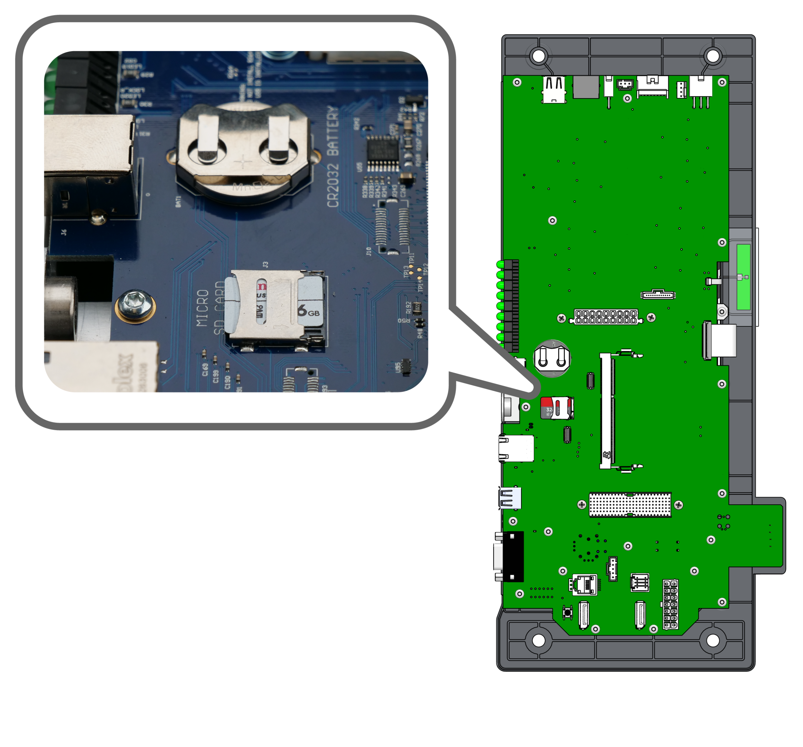
Komponenten suchen
Suchen Sie die Micro-SD-Karte und das Gehäuse der CR2032-Knopfzelle auf der Rückseite der Steuerplatine.
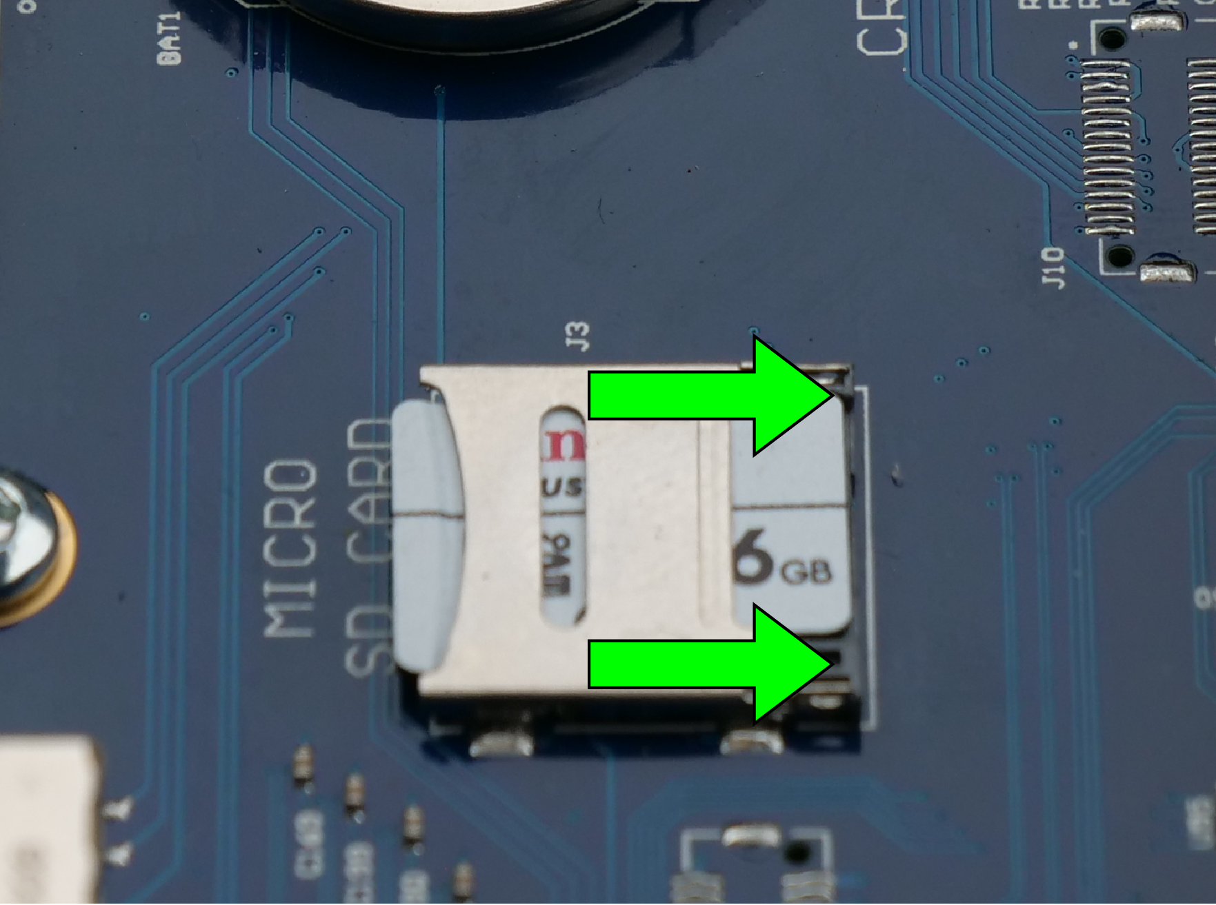
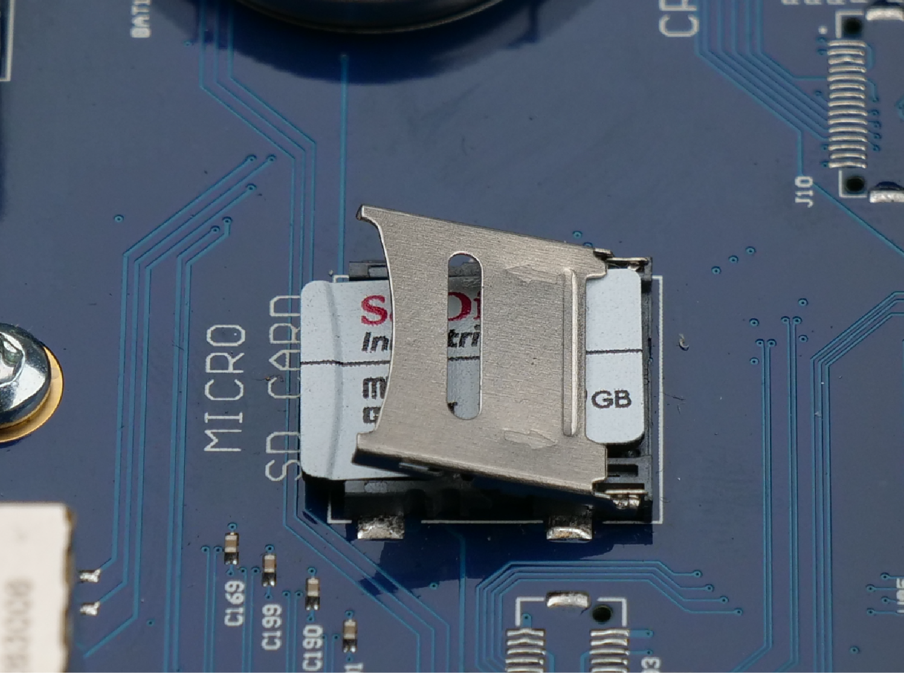
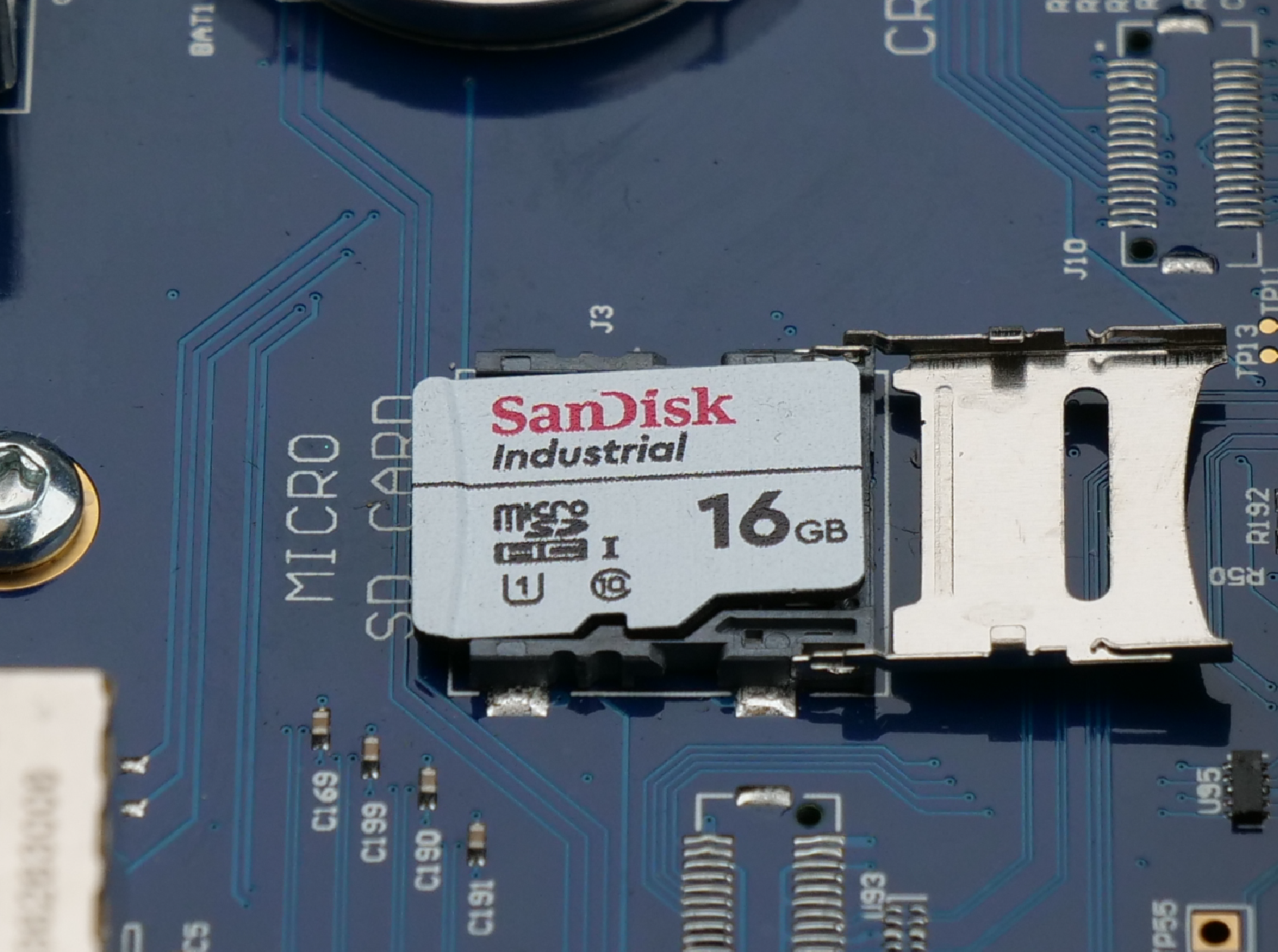
SD-Karte austauschen
Klicken Sie sich durch die Bildregisterkarten, um die Schritte zum Austausch anzuzeigen:
- Entriegeln: Schieben Sie die Metallverriegelung nach innen (in Pfeilrichtung), um sie zu entriegeln.
- Öffnen: Heben Sie den entriegelten Metallverschluss nach oben, um die SD-Karte freizulegen.
- Austausch: Entfernen Sie die alte SD-Karte, legen Sie die neue ein, schließen Sie die Klappe und schieben Sie den Verschluss wieder nach außen, um sie zu verriegeln.
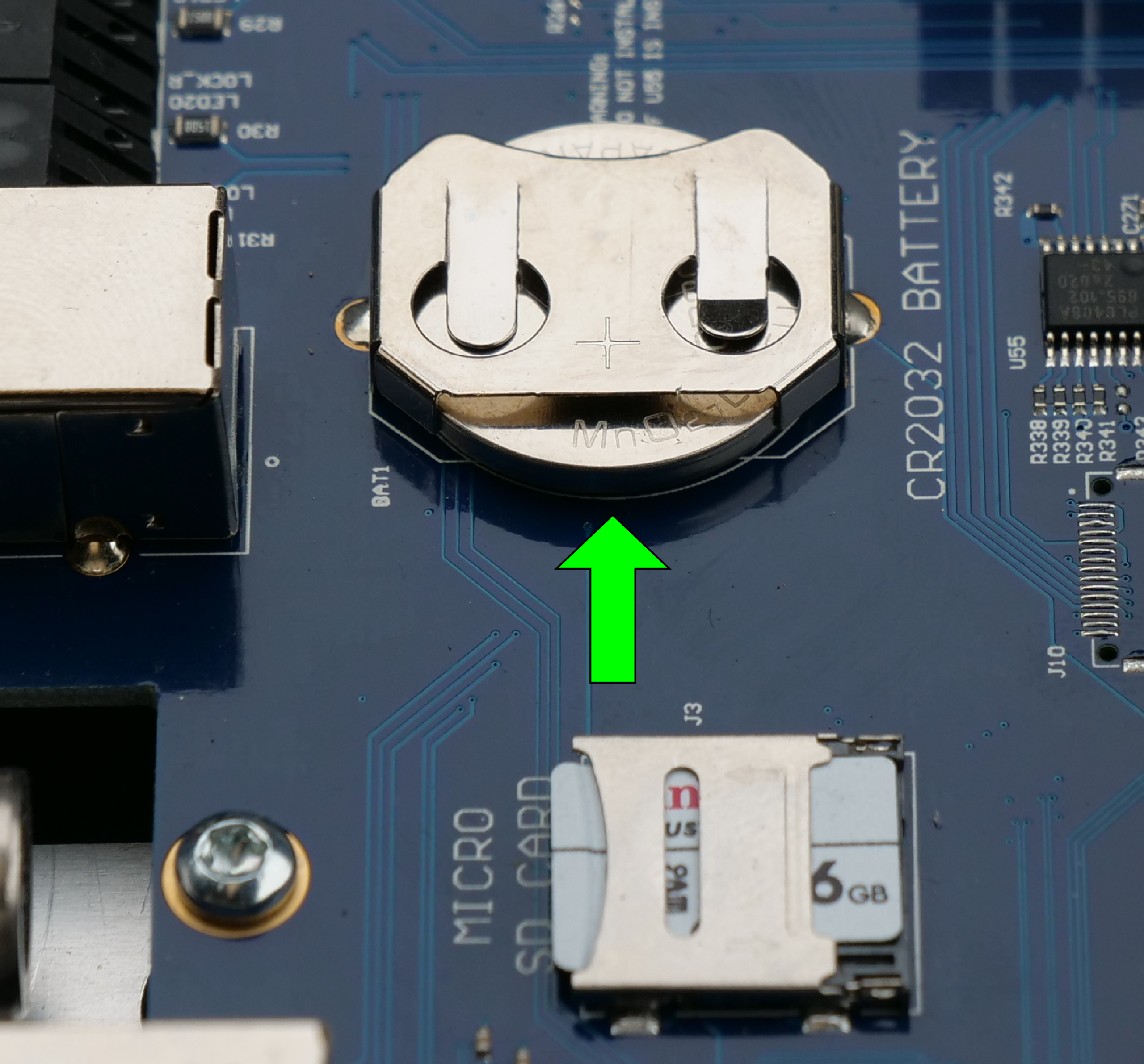
Knopfzelle austauschen
Suchen Sie das Fach für die Knopfzelle auf der Steuerplatine. Schieben Sie die alte Batterie vorsichtig aus ihrer Halteklammer heraus. Legen Sie die neue Batterie so ein, dass die Plusseite (+) nach oben zeigt.
Teil 3: Austausch der Backplane
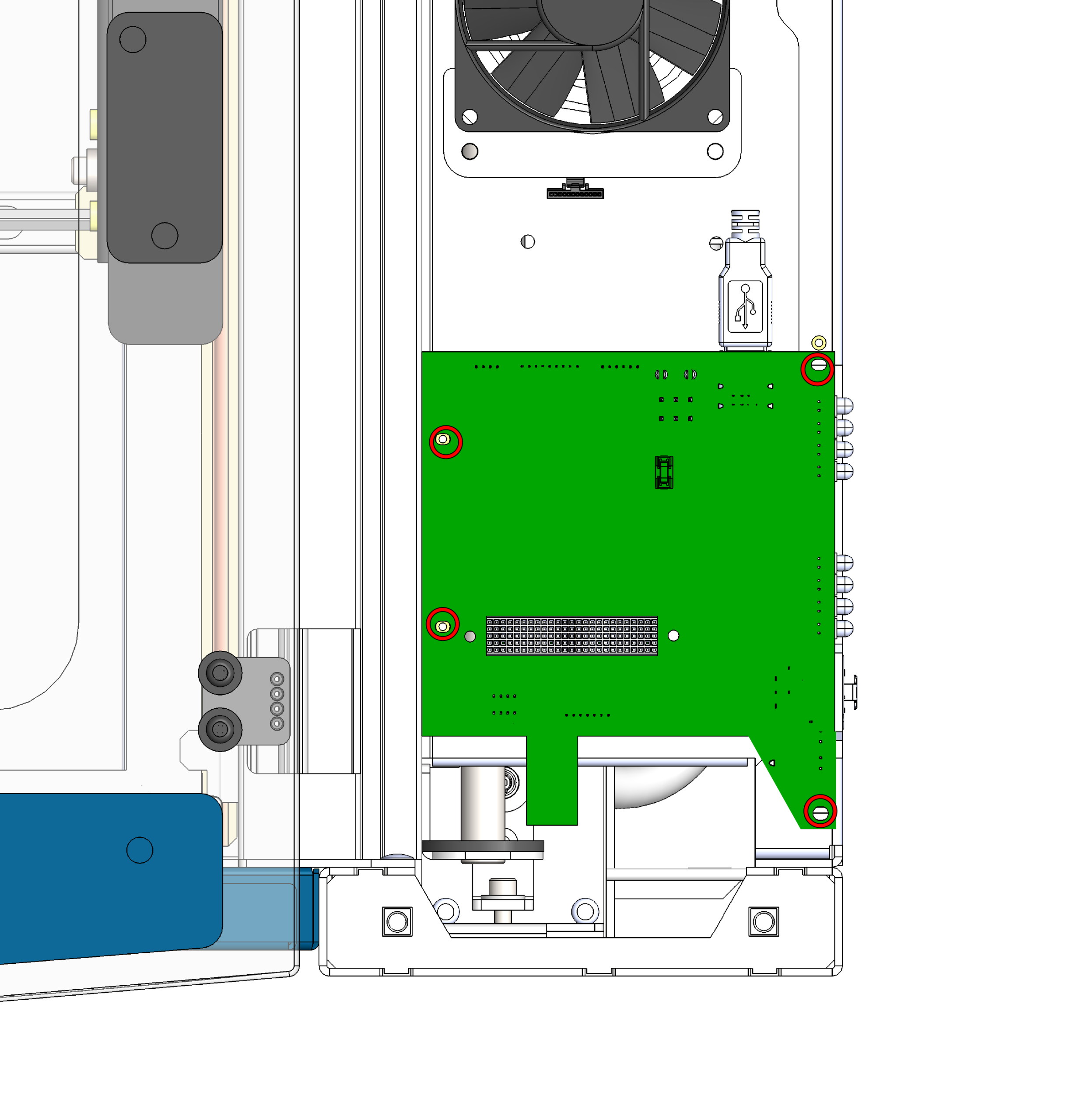
Schrauben der Rückwand entfernen
Suchen Sie die Backplane-Platine, die unterhalb der Steuerplatine angebracht ist, und lösen Sie die vier Schrauben, mit denen sie am Gehäuse befestigt ist.
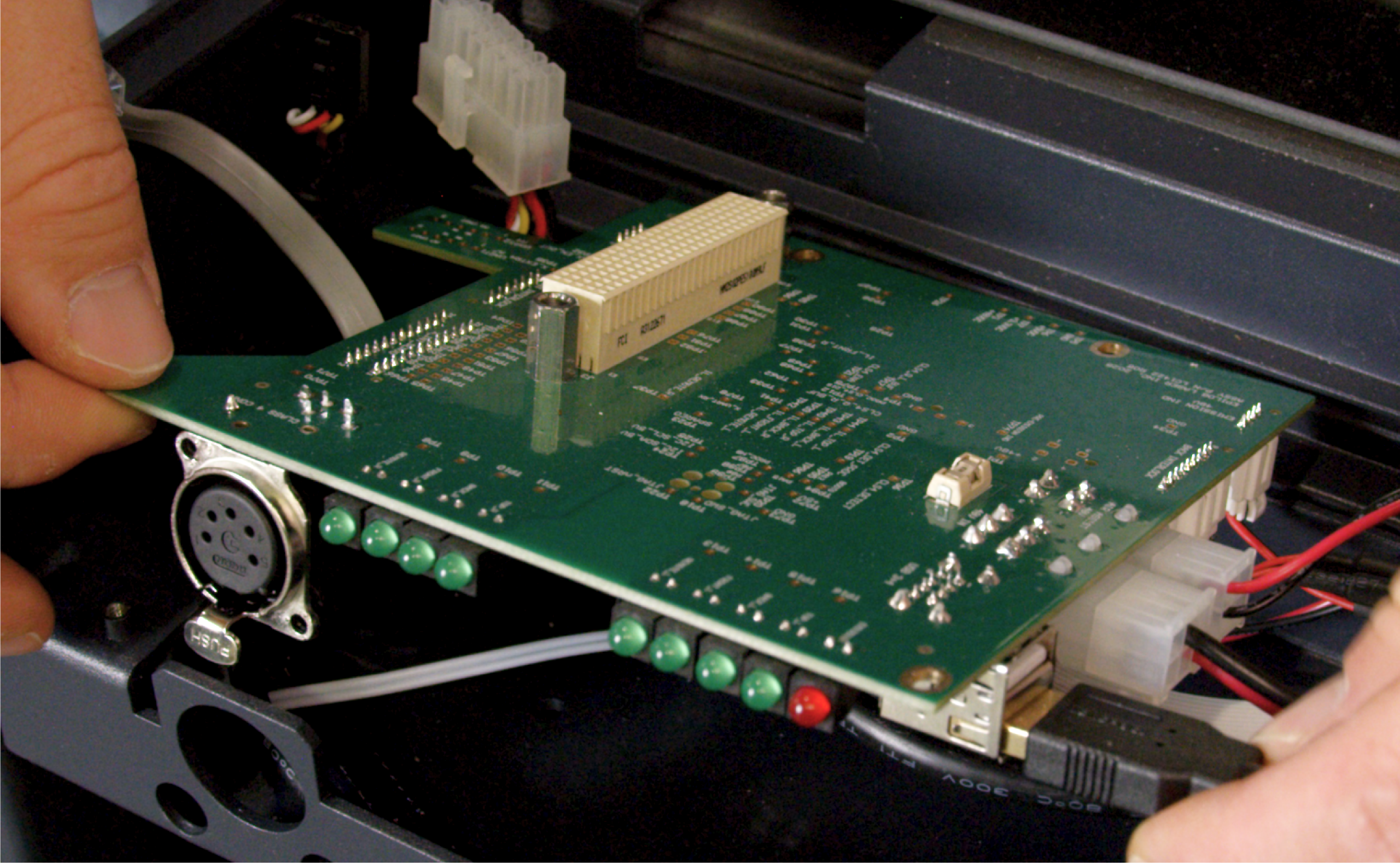
Kabel abziehen
Nachdem Sie die Platine abgeschraubt haben, trennen Sie vorsichtig alle daran angeschlossenen Kabelbäume und Kabel. Sobald alles abgeklemmt ist, heben Sie die Backplane aus dem Gerät heraus.
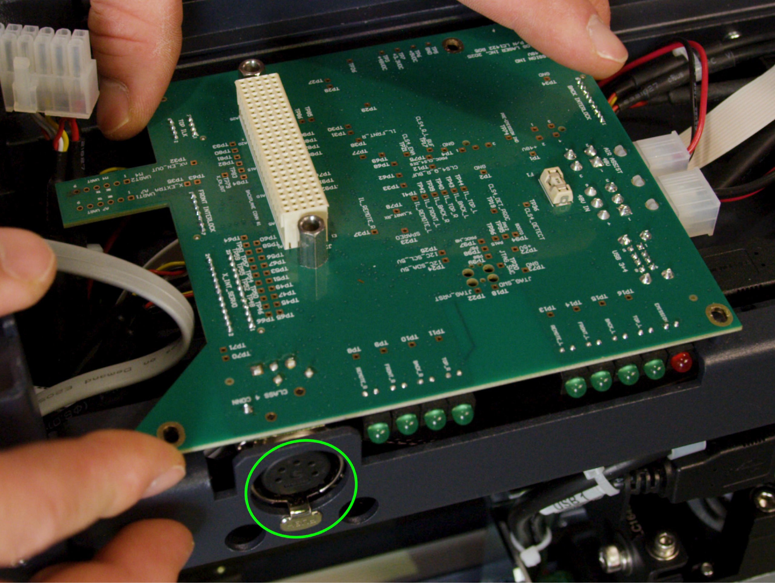
Ersatz-Backplane einbauen
Schließen Sie zunächst alle Kabel wieder an, die Sie in Schritt 9 entfernt haben. Sobald alle Kabel fest angeschlossen sind, richten Sie die Platine aus und befestigen Sie sie mit den 4 Schrauben wieder am Gehäuse.
Wichtig: Der Dongle-Anschluss der Klasse 4 verfügt über eine Lasche, die mit der Aussparung im Gehäuse ausgerichtet werden muss. Vergewissern Sie sich, dass die Lasche richtig in der Aussparung sitzt, bevor Sie die Schrauben festziehen, um eine Beschädigung des Anschlusses oder der Platine zu vermeiden.
Teil 4: Zusammenbau und Einbau
Kabelbaum der Steuerplatine wieder anschließen
Führen Sie die Steuerplatine (mit der neuen SD-Karte und der Batterie) vorsichtig an den Einbauort heran und schließen Sie die Kabelbäume wieder an die Platine an.
Sitzsteuerplatine
Richten Sie die Steuerplatine direkt über den Schraubenlöchern aus. Drücken Sie sie gleichmäßig und fest nach unten, um sicherzustellen, dass die Platine fest mit der neu installierten Rückwandplatine verbunden ist.
Sicherheitssteuerplatine
Setzen Sie die 4 Schrauben wieder ein und ziehen Sie sie fest, um die vollständig eingesetzte Steuerplatine am Gehäuse zu befestigen.
Seitenwand ersetzen
Setzen Sie die rechte Seitenwand des Geräts wieder ein und befestigen Sie sie.
Abschließende Überprüfung
Schließen Sie das Gerät wieder an die Steckdose an und schalten Sie es ein. Vergewissern Sie sich, dass der Touchscreen normal hochfährt und das Gerät erfolgreich initialisiert wird, was darauf hindeutet, dass die neue Platine, die SD-Karte, der Akku und die Backplane alle korrekt miteinander kommunizieren.