
Estimated time: 20–30 minutes • Skill: Intermediate
This document provides a step-by-step guide for aligning the FiberMark Laser Engraver to ensure optimal performance and accuracy. It outlines the necessary safety precautions and detailed alignment procedures to help users properly adjust the laser system.
To complete this procedure, you will need the Alignment Target provided with your system. Following these instructions will help maintain precision and prevent operational issues.
WARNING: UNDER NO CIRCUMSTANCES ARE YOU TO ATTEMPT TO OPERATE THE FIBERMARK LASER ENGRAVER WITH THE SAFETY INTERLOCKS DEFEATED, THE SIDE PANELS OR THE FRONT DOOR REMOVED. SERIOUS, PERMANENT EYE DAMAGE MAY OCCUR.
Alignment Procedure
-
Install the alignment target.
Place the alignment target in the lens carriage.
-
Turn on the red dot pointer.
Activate the red dot pointer from the control panel.
-
Disable X-Y motors.
Depress the “X-Y Off” button on the control panel.
-
Enable manual movement.
Depress the “Go” button. The carriage can now be moved freely around the table by hand.
-
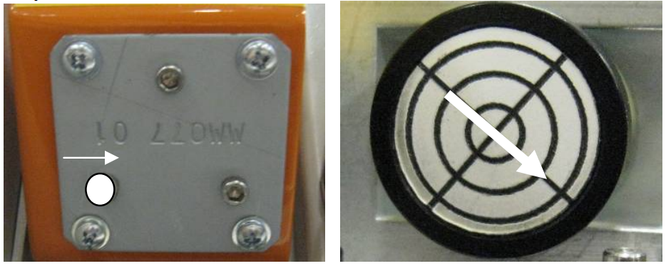
Move carriage to position 1.
Manually move the lens carriage to the left rear corner (position 1) of the engraver.
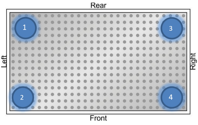
Picture 1 — Table positions. -
Check red dot position.
Check if the red dot is centered on the alignment target.
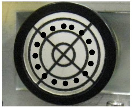
Picture 2 — Centered red dot. -
Remove the side panel.
Carefully remove the left-hand side panel to access the periscope mirrors.
-
Locate the periscope mirrors.
Identify the periscope assembly which contains two mirrors (upper and lower).
-
Adjust the lower periscope mirror.
If the red dot is not centered at position 1, adjust the lower periscope mirror using the adjustment screws until the dot is centered on the target.
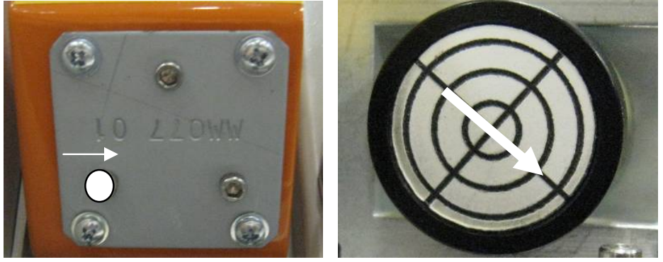
Picture 3 — Mirror adjustment diagram. 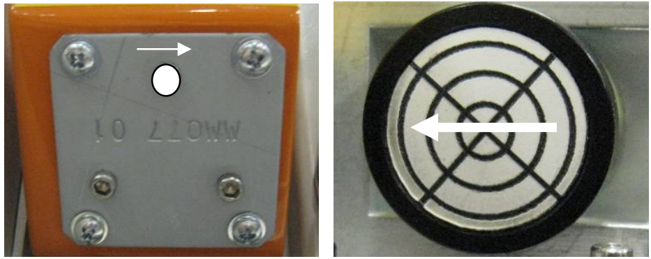
Picture 4 — Lower mirror location. 
Picture 5 — Lower mirror adjustment. -
Adjust the upper periscope mirror.
Move the lens carriage to the left front of the engraver. If the dot is off-center, adjust the upper periscope mirror until it is centered.
Picture 6 — Upper mirror location. 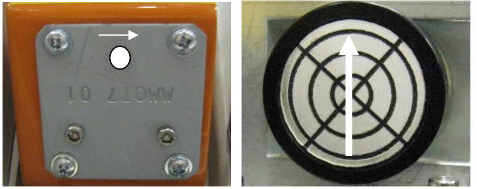
Picture 7 — Upper mirror adjustment. 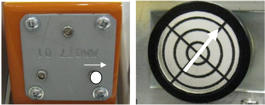
Picture 8 — Upper mirror adjustment screws. -
Verify position 1 alignment.
Move the carriage back to position 1 (left rear) to verify the red dot is still centered. Repeat adjustments if necessary.
-
Check rear X-Axis alignment.
Move the X-Axis rail all the way to the rear of the machine and check the dot’s position. Make minor adjustments if needed.
-
Check right-side alignment.
Move the lens carriage to the right side of the table (front right and rear right corners) and check alignment.
-
Final verification.
Move the carriage across the entire engraving table to ensure the red dot remains perfectly centered on the target throughout its range of motion. Once confirmed, replace the side panel.
