Estimated time: 30–45 minutes • Skill: Intermediate
To replace the X-Axis belt on an Epilog FiberMark laser, you must remove the X-Axis rail to allow access to the bearing guard and proper belt routing. This procedure involves three phases: removing the rail, replacing the belt, and reinstalling the rail and associated components.
To complete this procedure you’ll need a phillips screwdriver, scissors, and a replacement nylon tie for the ribbon cable. The steps include removing the rail, slackening and replacing the belt, re-securing the rail, and performing final alignment checks.
Procedure
-
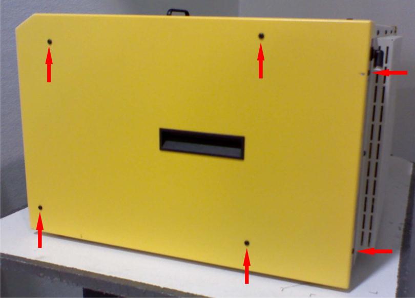
Power down and remove side panels.
Turn off the machine and unplug it. Remove both left and right side panels by unscrewing the six screws on each side (four on the side, two on the rear).
-
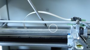
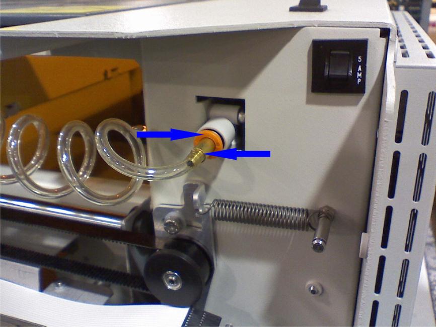
Disconnect the air assist line.
Remove the air assist connector from the X-Axis assembly by pressing the ring and pulling the connector free.
-
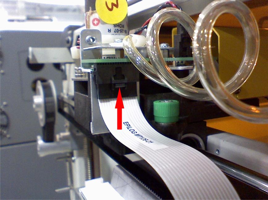
Unplug the white ribbon cable.
On the right side of the X-Axis rail, depress the thumb clip on the white ribbon cable connector and pull it down to unplug.
-
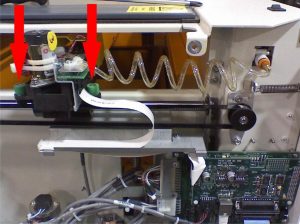
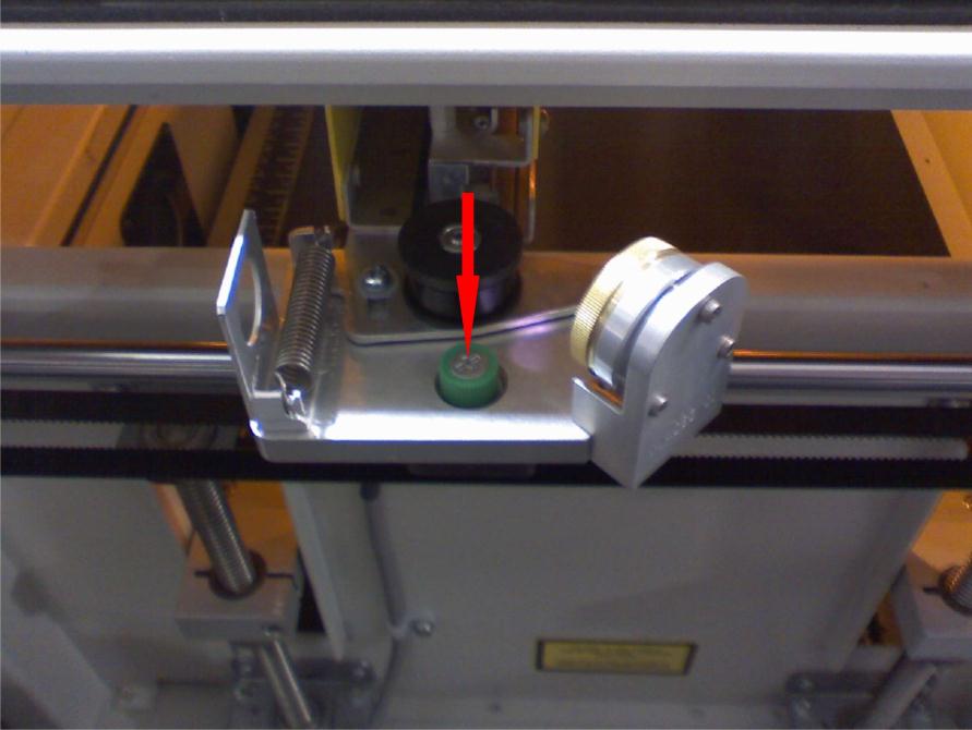
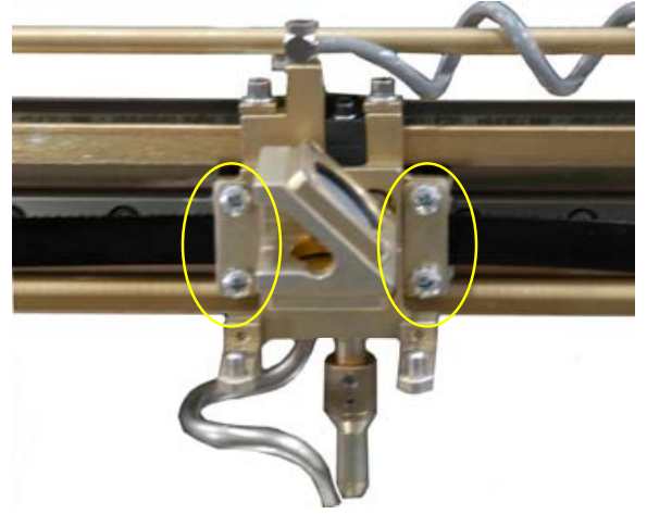
Loosen green-cased screws.
Loosen the two green-cased screws near the right side (one near the ribbon cable, one near the X motor) and the single green-cased screw on the left side.

-
Remove the X-Axis assembly.
Lift both sides of the rail to free it from the brackets. Slide the left side forward to clear the chassis and lift the assembly out carefully.
-
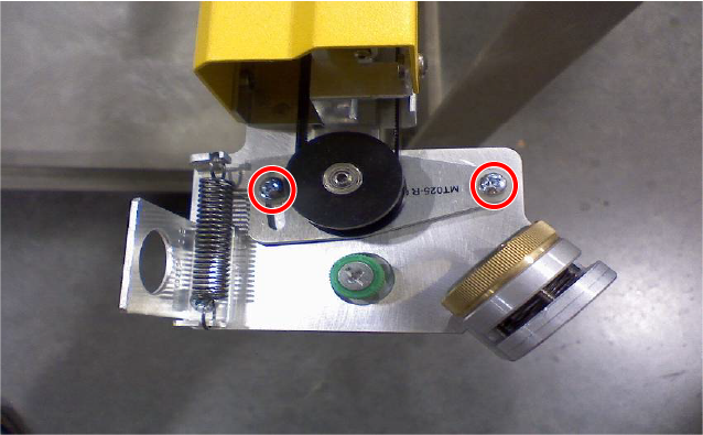
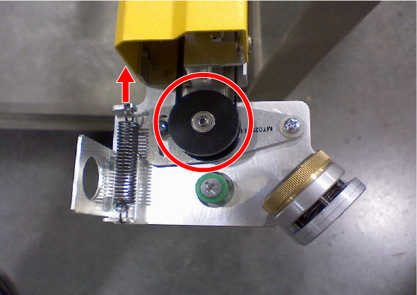
Slack the X-axis belt.
On the left side of the X-Axis rail, loosen the pulley tension screws. Press the pulley toward the machine to release belt tension and retighten the screws to hold the pulley in the slackened position.
-
Detach the old belt from the laser head.
Remove the screws and plates securing the belt to the lens assembly, leaving the belt routed but detached.
-
Install the new belt.
- Attach one side of the old belt to the new belt with a stapler, then pull the opposite end of the old belt to fish the new belt through the routing path.
- Attach one side of the new belt to the lens assembly and secure with screws.
- Cut the belt to proper length, seat under clamps, and tighten the screws.
- Check pulley alignment; ensure the belt runs centered without rubbing.
- Retension the belt by loosening the pulley screws, allowing the pulley to snap into position, then re-tighten the screws.
-
Reinstall the X-Axis assembly.
Reverse removal steps to reinstall the rail. Replace the ribbon cable tie with a new nylon tie, reconnect the air assist line, and secure all screws.
-
Reinstall panels and final checks.
Reattach side panels, reconnect power, and test X-Axis motion. Verify proper belt tension and alignment. For the detailed alignment procedure, refer to the FiberMark Alignment tech note linked on the right.