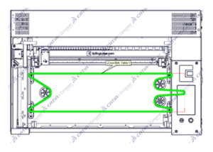
This guide covers replacing the table lead screws on the Fusion Maker, Fusion Edge and Fusion Pro 24 and 36. Some steps apply only to certain models and are labeled; unlabeled steps apply to all models.
Parts Required
- RC0612 – Lead Screw Assy Z Axis (some 24 x 12 tables)
- LC0792 – Assy, Lead Screw, Table (some 24 x 12 tables, all 24 x 24 and 36 x 24 tables)
Tools / Materials Required
- 5/32" Allen Wrench
- Phillips Screwdriver
- 9/16" or 11/16" Wrench (depending on model)
- Pencil or Marker
Safety First: Ensure the engraver is completely powered off and the power cord is disconnected before removing any panels or touching internal components.
Lead Screw Removal
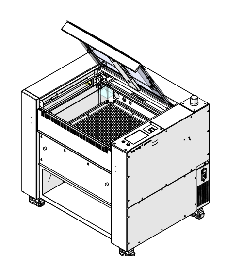
Lower the Table
Turn on the engraver and use the Focus menu to lower the table to the middle of the cabinet.
Turn Off Engraver
Turn off the engraver.
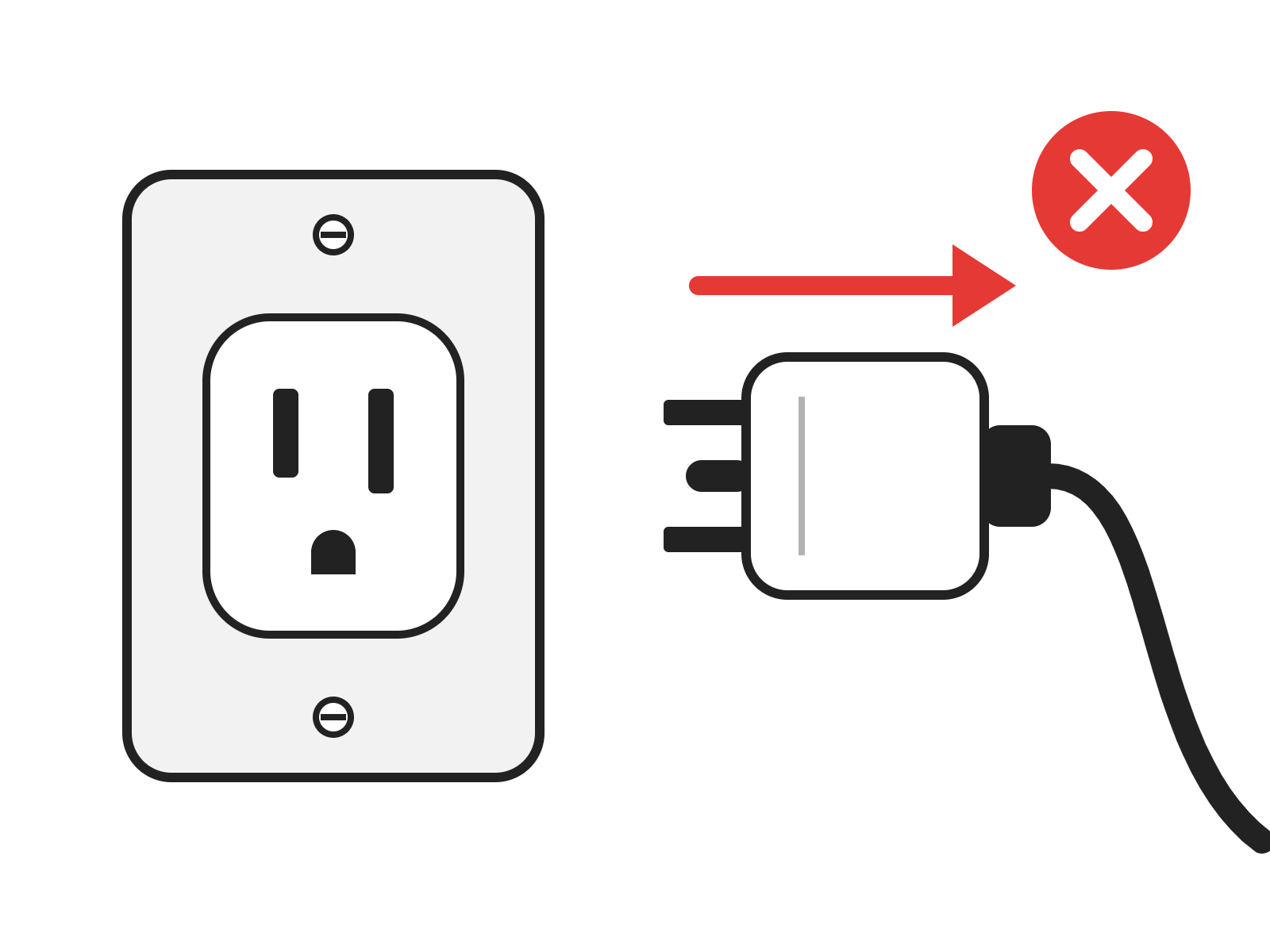
Disconnect from Power
Unplug the engraver from its power source.
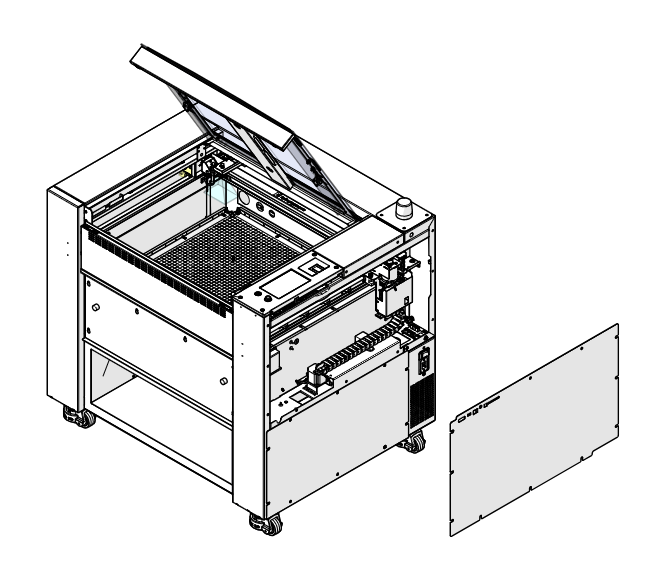
Remove Right Panel
Remove the right panel of the engraver.
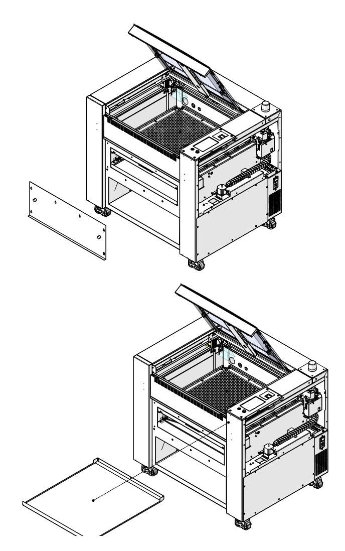
Remove Front Panel and Crumb Tray
Remove the front access panel and the crumb tray of the engraver.
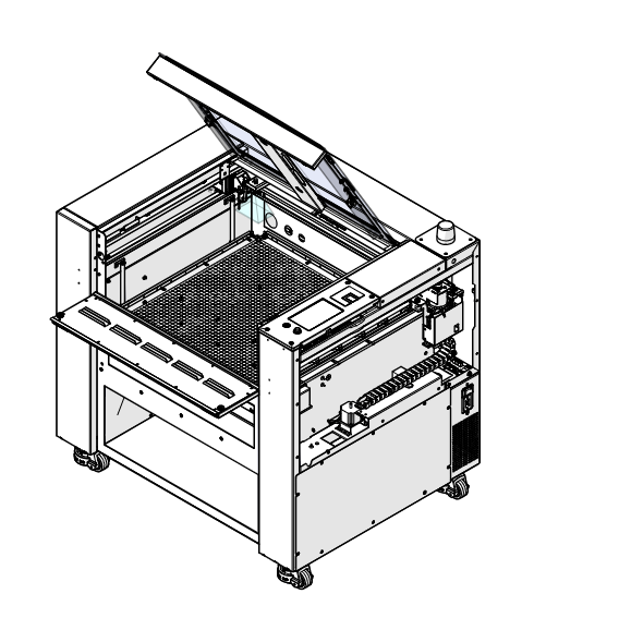
Lower the Front Door
Pro only Lower the front drop-down door.
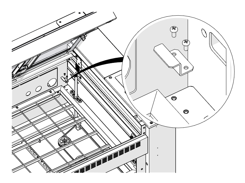
Remove Table Clamps
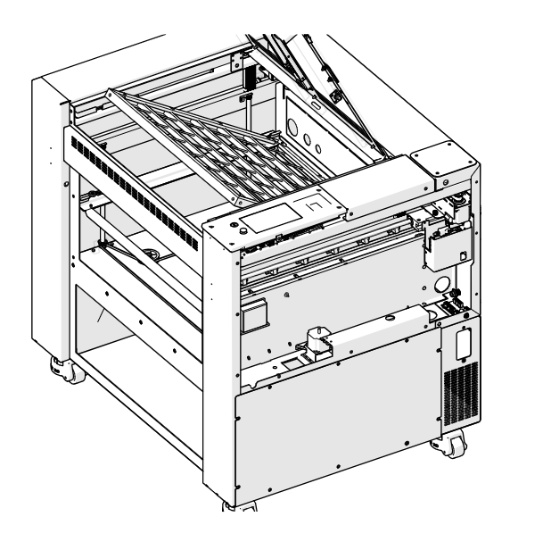
Edge and Maker only Loosen and remove the two Phillips screws that secure the table clamp to the table support structure at each corner of the table.
Remove the Table
Lift the table up to clear the table locator pins, then angle the front of the table upward and remove it from the engraver.
Mark the Motor Position
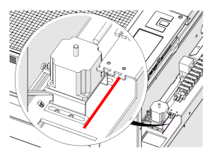
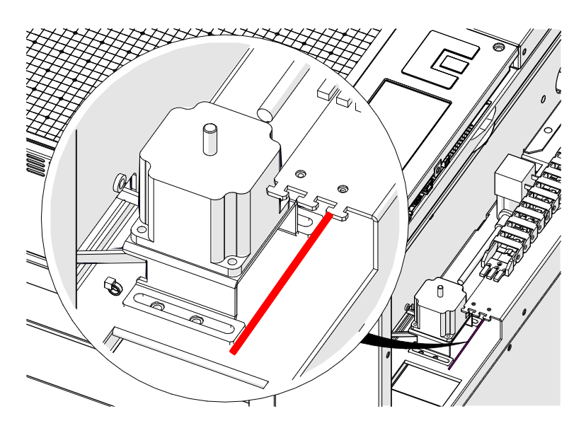
Use a pencil or marker to mark the engraver chassis at the leading edge of the table motor (shown in red). This mark is used to set the belt tension during installation.
Disconnect Motor Harness
Disconnect the table motor electrical harness.
Release Belt Tension
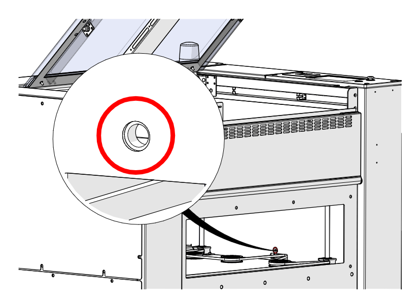
Loosen, but do not remove, the table motor tensioner thumbscrew (circled in red) to release the tension on the table belt.
Remove Motor Mount Screws
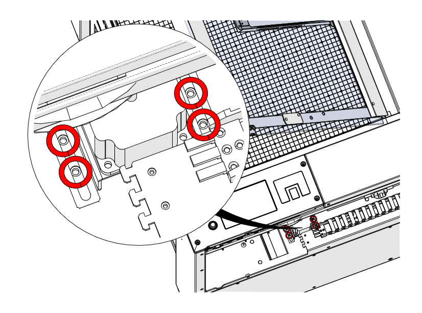
Loosen and remove the four 5/32" Allen screws on the table motor mount (circled in red).
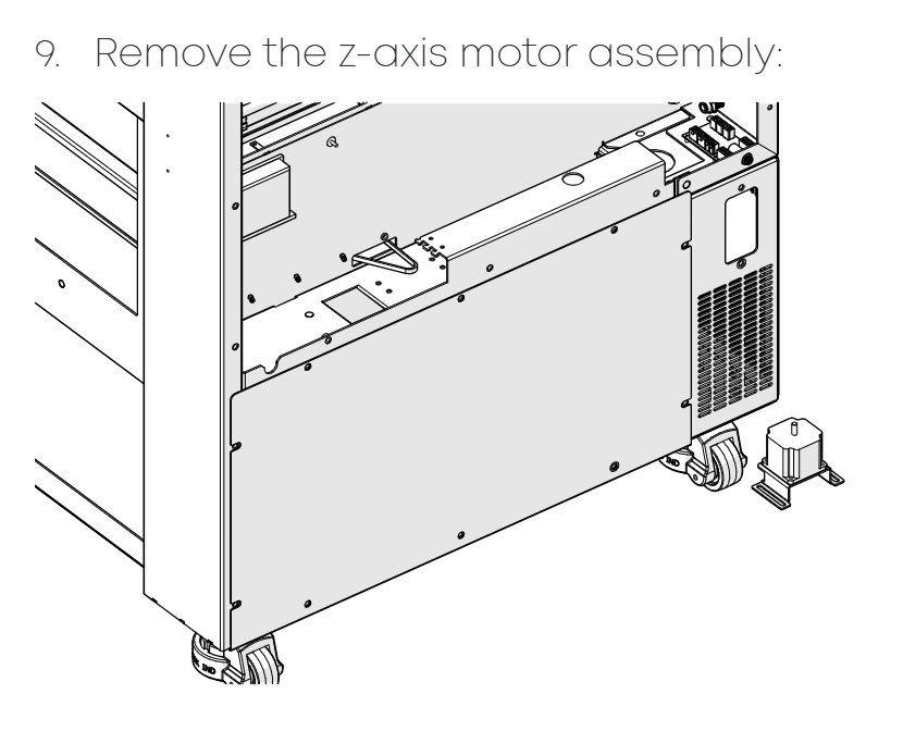
Remove the Table Motor
Remove the table motor assembly.
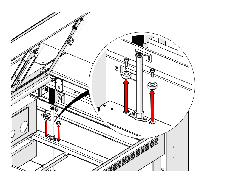
Remove Table Leveler Screws
At each corner of the table, loosen and remove the two 5/32" Allen screws and Delrin bumpers that secure the table leveler to the table support structure.
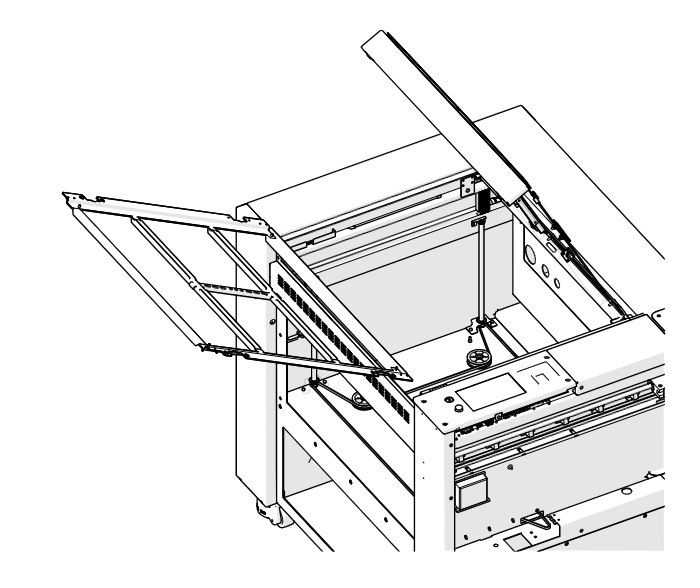
Remove the Table Support
Pro only Remove the table support structure from the engraver.
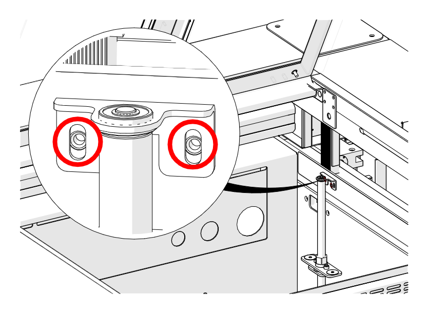
Remove Lead Screw Screws
At each corner of the table, loosen and remove the two Phillips screws that secure the lead screw to the engraver chassis (circled in red).
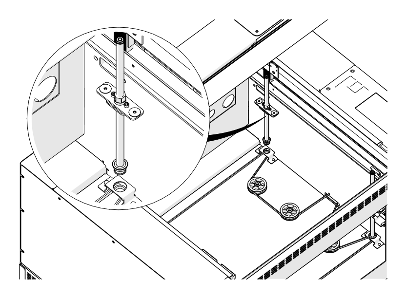
Remove the Lead Screws
At each corner of the table, remove the upper lead screw bracket and then the lead screw assembly.
Lead Screw Installation
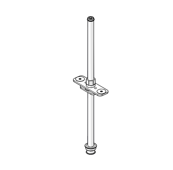
Position the Support Bracket
Position the lead screw table support bracket in the middle of the new lead screw assembly.
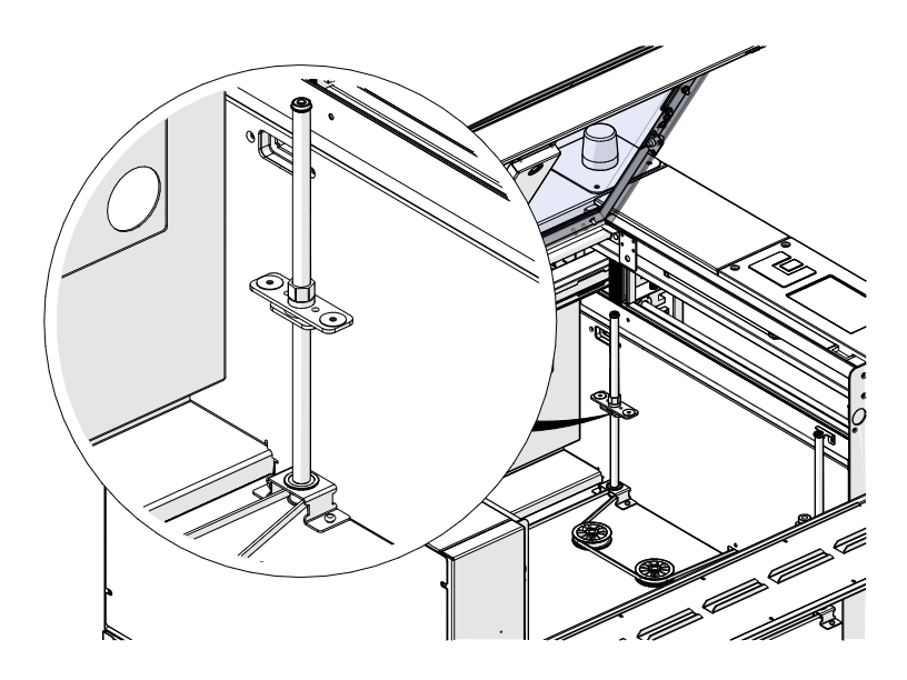
Install the Lead Screws
At each corner of the table, install the lead screw assembly in the lower lead screw bracket, making sure the table belt wraps around the lead screw pulley.
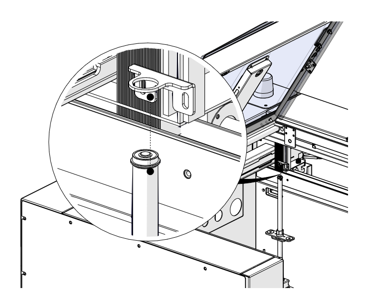
Install Upper Brackets
Install the upper lead screw bracket over the lead screw at each corner of the table.
Install Lead Screw Screws
At each corner of the table, install and tighten the two Phillips screws that secure the lead screw to the engraver chassis.
Install the Table Support
Pro only Place the table support structure in the engraver.
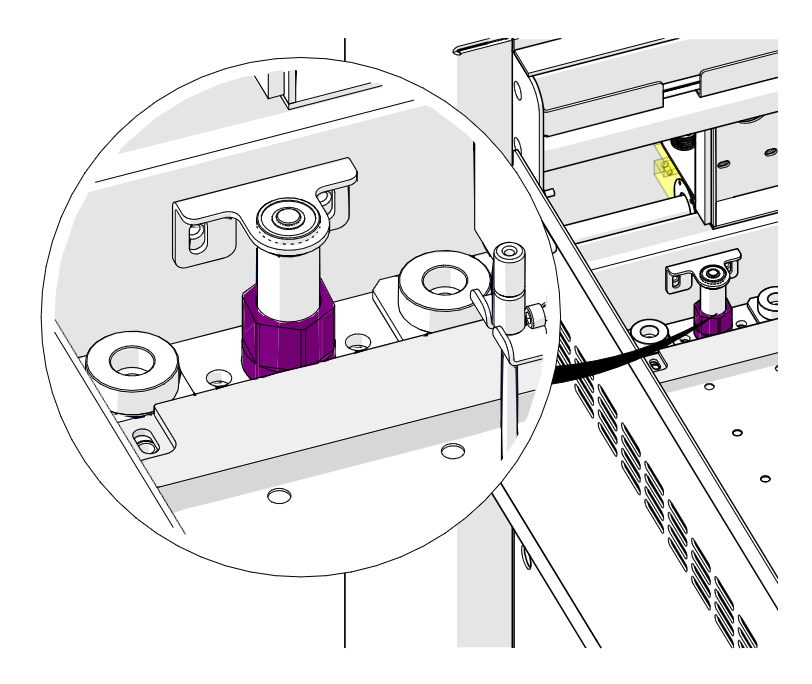
Level the Table Support
Turn the lead nut on each lead screw (highlighted in purple) with a 9/16" or 11/16" wrench, depending on the model, to level the table support structure.
Note: Pick a fixed reference point in the engraver cabinet and adjust every lead screw to line up with it.
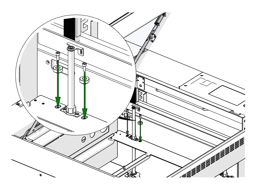
Install Table Leveler Screws
At each corner of the table, install and tighten the two 5/32" Allen screws and Delrin bumpers that secure the table leveler to the table support structure.
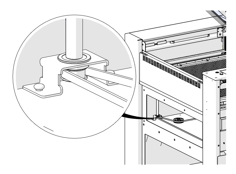
Check the Lead Screw Pulleys
Make sure the table belt is still around every lead screw pulley. If it has dropped below a pulley, reposition it around the pulley.
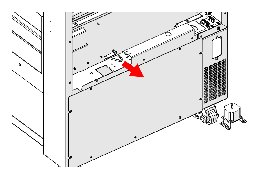
Pull the Belt Out
Pull the table belt out from the machine so it will wrap around the table motor drive pulley when the motor is installed.
Install the Table Motor
Place the table motor in its housing. Install, but do not fully tighten, the four 5/32" Allen screws on the motor mount.
Recheck the Pulleys
Check every lead screw pulley again and reposition the belt if it has dropped below any of them.
Tension the Belt
Tighten the table motor tensioner thumbscrew until the leading edge of the motor lines up with the mark made in step 9. Then tighten the four 5/32" Allen screws on the motor mount.
Connect Motor Harness
Reconnect the table motor electrical harness.
Install the Table
Insert the vector grid or raster table into the table support structure.
Install Table Clamps
Edge only Install the table clamps with the two Phillips screws at each corner of the table.
Install Crumb Tray and Panels
Install the crumb tray, the front access panel and the right side panel of the engraver. On a Pro, close the front drop-down door.
Power On
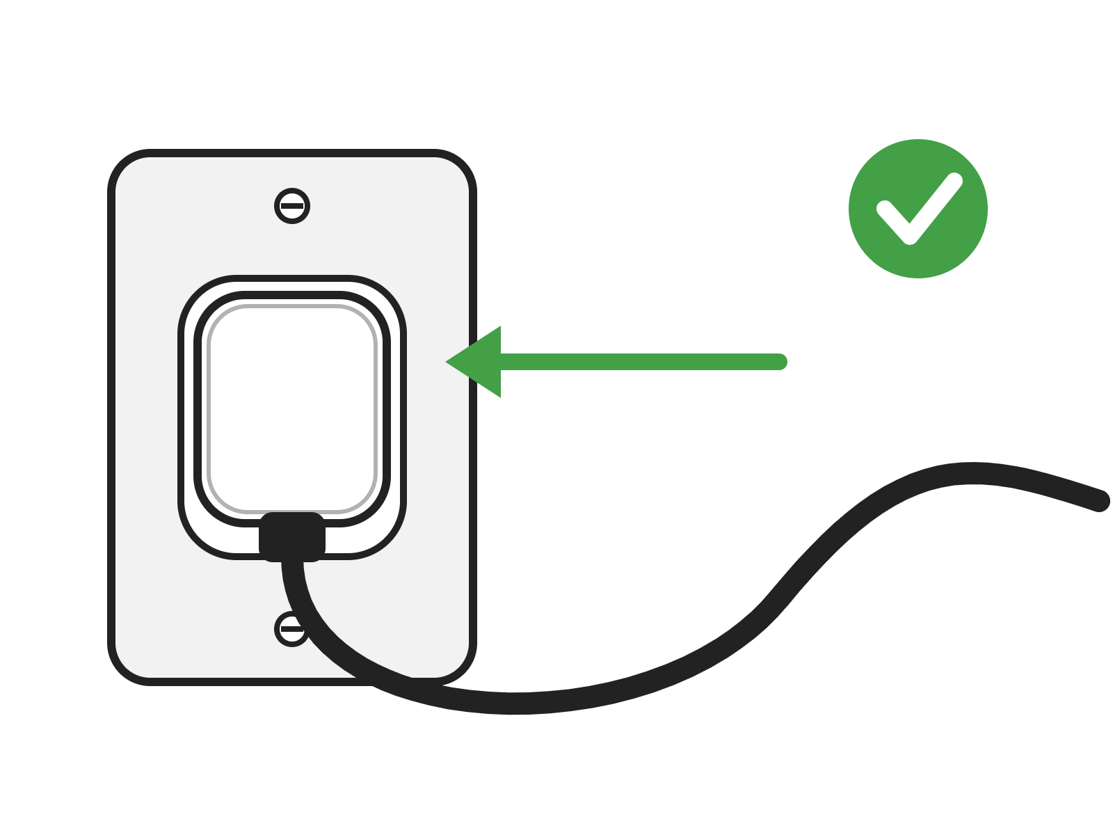
Reconnect the engraver to power and turn it on.